This is a repository copy of
Low order harmonic cancellation in a grid connected multiple
inverter system via current control parameter randomization
.
White Rose Research Online URL for this paper:
http://eprints.whiterose.ac.uk/855/
Article:
Armstrong, M., Atkinson, D.J., Johnson, C.M. et al. (1 more author) (2005) Low order
harmonic cancellation in a grid connected multiple inverter system via current control
parameter randomization. IEEE Transactions on Power Electronics, 20 (4). pp. 885-892.
ISSN 0885-8993
https://doi.org/10.1109/TPEL.2005.850949
[email protected] https://eprints.whiterose.ac.uk/
Reuse
Unless indicated otherwise, fulltext items are protected by copyright with all rights reserved. The copyright exception in section 29 of the Copyright, Designs and Patents Act 1988 allows the making of a single copy solely for the purpose of non-commercial research or private study within the limits of fair dealing. The publisher or other rights-holder may allow further reproduction and re-use of this version - refer to the White Rose Research Online record for this item. Where records identify the publisher as the copyright holder, users can verify any specific terms of use on the publisher’s website.
Takedown
If you consider content in White Rose Research Online to be in breach of UK law, please notify us by
Low Order Harmonic Cancellation in a Grid
Connected Multiple Inverter System Via
Current Control Parameter Randomization
Matthew Armstrong, David J. Atkinson, C. Mark Johnson
, Member, IEEE
, and Tusitha D. Abeyasekera
Abstract—In grid connected multiple inverter systems, it is normal to synchronize the output current of each inverter to the common network voltage. Any current controller deficiencies, which result in low order harmonics, are also synchronized to the common network voltage. As a result the harmonics produced by individual converters show a high degree of correlation and tend to be additive. Each controller can be tuned to achieve a different harmonic profile so that harmonic cancellation can take place in the overall system, thus reducing the net current total harmonic distortion level. However, inter-inverter communication is re-quired. This paper presents experimental results demonstrating an alternative approach, which is to arrange for the tuning within each inverter to be adjusted automatically with a random compo-nent. This results in a harmonic output spectrum that varies with time, but is uncorrelated with the harmonic spectrum of any other inverter in the system. The net harmonics from all the inverters undergo a degree of cancellation and the overall system yields a net improvement in power quality.
Index Terms—Low order harmonics, multiple inverter systems, net harmonics.
I. INTRODUCTION
M
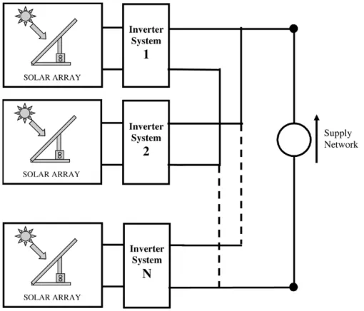
ULTIPLE string inverters are frequently used to connect a PV system to the network [1]. In this approach, each panel is connected through its own inverter, the inverter units being connected in parallel up to the required volt-ampere rating of the system (Fig. 1). This avoids the need to run long lengths of high current dc cabling, with the attendant problems of ex-pensive circuit breakers. It is normal practice for the output cur-rent of each inverter to be controlled to be sinusoidal, with low harmonic levels, and at unity power factor with respect to the network voltage.Low harmonic levels are desirable since harmonics have long been recognized as causing a number of operational problems to the grid network [2]–[4]. Some of the major effects caused by harmonics include capacitor bank failure, overvoltage and overcurrent on the network, dielectric breakdown of insulated
Manuscript received April 2, 2004; revised October 15, 2004. This work was supported by the Engineering and Physical Sciences Research Council (EPSRC), U.K., Intelligent Power Systems, Ltd. (IPS), Gateshead, UK, Scottish Power Plc, U.K., and BP Solar. Recommended by Associate Editor H. du T. Mouton.
M. Armstrong, D. J. Atkinson, and T. D. Abeyasekera are with the Depart-ment of Electrical and Electronic Engineering, School of Electrical, Electronic and Computer Engineering, University of Newcastle upon Tyne, Newcastle upon Tyne NE1 7RU, U.K. (e-mail: [email protected]).
C. M. Johnson is with the Department of Electronic and Electrical Engi-neering, University of Sheffield, Sheffield S1 3JD, U.K.
[image:2.594.300.555.194.412.2]Digital Object Identifier 10.1109/TPEL.2005.850949
Fig. 1. Grid connected, multiple string inverter system.
cables and kWh metering errors. To preserve the quality of the utility current and voltage, set limits are imposed on the current and voltage harmonics that may be injected into the grid [5], [6]. However, as more and more distributed generation systems are being interfaced to the network, the problem of harmonic injec-tion into the grid is becoming an increasing problem [7]–[12]. For this reason, there is considerable motivation to improve grid connected inverter performance through the reduction, or ide-ally complete elimination, of the output harmonics.
Several techniques aimed at inverter system harmonic im-provement have been presented. Holmes and McGrath [13] con-sidered the effect of a number of different PWM strategies in various converter topologies. It was demonstrated that certain PWM strategies and sampling techniques could help eliminate particular side-band switching harmonics. This work also iden-tified further opportunities for harmonic elimination in multi-level cascaded inverter systems. Lianget al.[14] described the use of Walsh Functions in a single phase full bridge inverter for the purpose of voltage harmonic elimination at the inverter output. The Walsh Function technique allowed the harmonic amplitudes of the inverter output voltage to be expressed as functions of the inverter switching angles. A series of linear al-gebraic equations could then be solved to eliminate unwanted harmonics. Infield [15] discussed the manner in which random
886 IEEE TRANSACTIONS ON POWER ELECTRONICS, VOL. 20, NO. 4, JULY 2005
phase harmonics in multiple inverter systems combined. In par-ticular, the work was applicable to switching harmonics, which are random in phase. Mathematical rules, based on probabilistic integrals, were formulated to help assess the overall degree of harmonic cancellation arising from multiple connection of in-verter systems to a common point.
This paper suggests a new idea to improve the overall current harmonic output of a grid connected multiple inverter system. In particular, the work focuses on reducing low order current harmonics. This is achieved through simple randomization of the inverter current control parameters. This technique is shown to significantly reduce the correlation of low order current har-monics between inverters. As a result, on average, the inverter harmonics at the common point of coupling are likely to demon-strate a degree of cancellation, as opposed to harmonic rein-forcement when correlated.
II. GRIDCONNECTEDINVERTERHARMONICS
The harmonics in the output current of an inverter can be grouped according their source: switching harmonics which are related to the PWM circuits in each inverter and lower frequency harmonics which are due to deficiencies in the control of the in-verter output current. The majority of the switching harmonics are easily filtered at the inverter output. The low order har-monics, however, are at frequencies much closer to the funda-mental. Therefore, it is more difficult to filter these harmonics without impairing the fundamental current waveform.
The output current harmonics related to the PWM are syn-chronized to the clock circuits within the inverter controller and therefore, will not be correlated because the crystal con-trolled clocks within each inverter are usually independent. A recognized power quality benefit of this arrangement is that the harmonic distortion arising in each inverter is uncorrelated and therefore cancellation will take place in multiple inverters sys-tems. The harmonics due to the current controller performance will, however, behave differently. It is normal to produce a cur-rent reference waveform within the inverter, which specifies the magnitude and power factor of the output current in accordance with the active and reactive power generation requirements at a particular time. For a grid connected system, the current ref-erence waveform in each inverter must be synchronized to the common network voltage waveform. Therefore, any low order harmonics resulting from controller deficiencies will also be synchronized to the common network voltage and the harmonics produced by individual converters will have a high degree of correlation. This will mean that the lower order harmonics from each inverter will be additive.
[image:3.594.303.555.64.255.2]The grid-connected inverter has to drive current against the supply voltage and impedance, which are not fixed quantities. Grid connected inverter performance has been shown to be very much dependent on grid operating conditions [16]. Controlling current to be injected into the grid network is, therefore, con-siderably more difficult than controlling current into fixed loads such as motor windings or isolated consumer load systems. The output current waveform fidelity is dependent on the tuning of
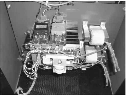
Fig. 2. Experimental H-bridge inverter module.
the current control loop but changes in the grid supply character-istics mean that it is not possible to achieve an optimally tuned output current loop at all times. Normally the inverter output current is tuned by adjusting settings within the controller while monitoring the low order harmonics. By trial and error, var-ious harmonics can be minimized and total harmonic distortion (THD) can be reduced. A point is normally reached where fur-ther tuning does not produce any furfur-ther improvement in THD. By adjustments to the controller tuning, however, it is possible to alter which harmonics are suppressed while maintaining the total harmonic distortion reasonably constant. This is due to the interaction between the controller dynamics and the dynamics of the supply and line inductance.
A. Harmonic Cancellation Scheme
In principle, for a multiinverter system, each controller could be tuned to achieve a different harmonic profile. Harmonic can-cellation would take place in the overall system and the net THD level would be reduced. To force this to happen, how-ever, inter-inverter communications would be required, a fea-ture which is not desirable on cost grounds. An alternative ap-proach is therefore considered, which is to arrange for the tuning within each inverter to be adjusted automatically with a random component. This will result in a harmonic output spectrum that varies with time but is uncorrelated with the harmonic spectrum of any other inverter in the system. As a consequence, the net harmonics from all the inverters will undergo a degree of can-cellation while each individual inverter THD will remain almost constant. Thus, the overall system of inverters yields a net im-provement in power quality.
III. EXPERIMENTALARRANGEMENT ANDRESULTS
Fig. 3. Experimental H-bridge inverter. Single inverter grid connected system.
Fig. 4. Inverter current control scheme: PI with terminal voltage feed-forward control.
A. Experimental Results With Conventional Current Control Techniques
Initially, each inverter is operated independently as a single grid connected unit with a conventional current control loop. Each inverter operates from an independent 50-V dc bus, and is connected to a 20-Vrms ac grid voltage (Fig. 3). Harmonic data is acquired through the use of a power analyzer, which is capable of calculating and displaying harmonic spectra and THD information. The power analyzer is set up to acquire the harmonic data over 16 fundamental current cycles, util-ising a Hanning sampling window. This is in keeping with recommended methods for measurement and interpretation of harmonic information [17]. All harmonic and THD results presented in this paper are acquired under these conditions.
Each H-Bridge is switched with a unipolar switching PWM scheme at 20 kHz. A proportional-integral (PI) current control loop (Fig. 4), with supply voltage feed-forward, is implemented with a 50- s current sampling interval. The PWM output is scaled according to the measured dc link voltage. The controller thus compensates for any change in the dc link voltage. Each in-verter is tuned independently via the software parameters: pro-portional gain, Kp and integral gain, Ki, to achieve the best output current fidelity possible. Each inverter is controlled to operate at unity power factor with respect to the grid voltage. This is shown in Fig. 5 for one of the experimental inverters.
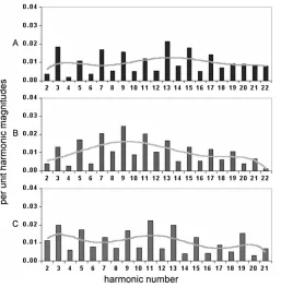
[image:4.594.40.292.219.328.2]Via the power analyzer, the harmonic spectrum of the output current is recorded for each inverter. The results obtained repre-sent a snap shot in time of the performance of each inverter. To evaluate the average performance of each inverter over time, the harmonic spectrum of all three inverters is recorded at six sepa-rate intervals. An averaged harmonic spectrum is then calculated and considered to be a typical measure of inverter performance.
Fig. 5. Unity power factor operation of inverter 1. Time Base. 10 ms/div, Trace A: Grid voltage 30 V/div, Trace B: Inverter 1 output current 10 A/div.
Fig. 6. Low order harmonic spectra: Inverter output current with conventional PI control. Each inverter, grid connected and operating independently. Trace A: Inverter 1, harmonic spectrum of inverter output current, Trace B: Inverter 2, harmonic spectrum of inverter output current, Trace C: Inverter 3, harmonic spectrum of inverter output current.
The averaged harmonic data is imported into Microsoft Excel for presentation in graphical format.
[image:4.594.304.552.296.574.2]888 IEEE TRANSACTIONS ON POWER ELECTRONICS, VOL. 20, NO. 4, JULY 2005
Fig. 7. Correlated harmonic trend lines for independently operated inverters, when controlled by conventional current control method.
Fig. 8. Experimental, parallel connected inverter system comprising of three inverter units.
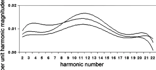
Using the Microsoft Excel trend line function, a sixth order polynomial trend line is imposed on each graph. This produces an harmonic profile for each inverter over the averaged set of harmonic data. The results show a strong correlation in harmonic profile for each of the three inverters under test. This correlation is more obviously noticed when the trend lines are superimposed on the same axis, as shown in Fig. 7.
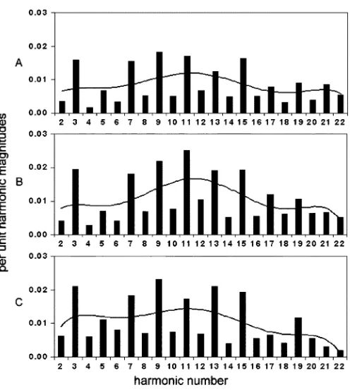
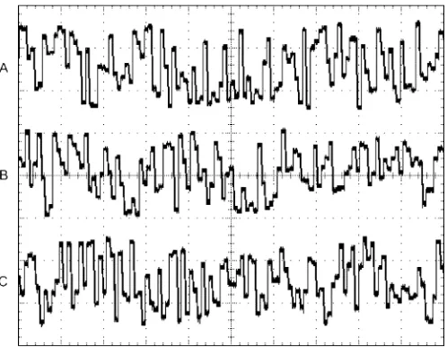
[image:5.594.40.289.69.181.2]All three inverters are then connected together at their output to form a parallel, three inverter, grid connected system as shown in Fig. 8. Each inverter is current controlled with the same controller tuning as previously determined for single inverter use. All three inverters operate at unity power factor with respect to the grid voltage. Six sets of harmonic data are collected, and once again an averaged harmonic spectrum is determined for each inverter (Fig. 9). In each case, it can be seen the largest distortion components are at the third, seventh, ninth, and 11th harmonic. Again, the resultant harmonic trend lines, shown in Fig. 10, highlight a strong correlation in harmonic profile for each of the three inverters under test. The same trend line is seen in the overall system output current, where similar
Fig. 9. Low order harmonic spectra: Inverter output current with conventional PI control. Grid connected parallel inverter system. Trace A: Inverter 1, harmonic spectrum of inverter output current, Trace B: Inverter 2, harmonic spectrum of inverter output current, Trace C: Inverter 3, harmonic spectrum of inverter output current, Trace D: Harmonic spectrum of parallel inverter system output current.
Fig. 10. Correlated harmonic trend lines for parallel inverter system, when controlled by conventional current control method.
[image:5.594.42.287.223.481.2] [image:5.594.305.554.483.618.2]Fig. 11. Inverter current control scheme, with randomized control parameters.
Fig. 12. Random number generator for each inverter module. Used to develop randomly varying proportional gain parameter, Time Base. 2 ms/div, Trace A: Inverter 1, random number generator, Trace B: Inverter 2, random number generator, Trace C: Inverter 3, random number generator.
injected into the grid. For this reason, randomization of the cur-rent control is considered as a method of preventing harmonic reinforcement.
B. Experimental Results With Randomized Current Control Techniques
Fig. 11 shows the modified control scheme implemented to produce un-correlated harmonic performance in each inverter. In this approach, the proportional gain of each inverter is ran-domly adjusted in real time. To achieve this, a random gain com-ponent, Rp is added to the already established optimum propor-tional gain, Kp. The random component may be a positive or negative number, but its magnitude is limited so, when added to Kp, excessive deviation from the optimal controller tuning is prevented. This creates an effective tolerance band around the optimal tuning position and is necessary to maintain acceptable current controller performance. In this instance, a % toler-ance band is found to be acceptable.
The random gain component, Rp, is established through the software generation of a random number. Each current controller generates a string of random numbers, which in turn produces a randomly varying signal (Fig. 12). The random number signal from each controller is then filtered through a simple three-pole digital filter, to smooth the variation in the
Fig. 13. Random component of proportional gain, kpr, for each inverter module. Produced by digital filtering of random number generator, Time Base: 2 ms/div, Trace A: Inverter 1, random component of proportional gain, Rp1, Trace B: Inverter 2, random component of proportional gain, Rp2, Trace C: Inverter 3, random component of proportional gain, Rp3.
[image:6.594.40.289.209.402.2]890 IEEE TRANSACTIONS ON POWER ELECTRONICS, VOL. 20, NO. 4, JULY 2005
[image:7.594.308.556.63.400.2]Fig. 14. Low order harmonic spectra: Inverter output current with randomized control parameters. Each inverter, grid connected and operating independently, Trace A: Inverter 1, harmonic spectrum of inverter output current, Trace B: Inverter 2, harmonic spectrum of inverter output current, Trace C: Inverter 3, harmonic spectrum of inverter output current.
Fig. 15. Uncorrelated harmonic trend lines for individual inverters, when controlled with randomized current control method.
As such, it was considered preferential to leave this parameter unchanged.
[image:7.594.40.290.410.517.2]Due to the inclusion of the controller randomization, the per-formance of each inverter varies with time. Therefore, a defini-tive assessment of the randomized control strategy cannot be de-termined from a single set of results taken at only one instance in time. For this reason, the performance improvement, or oth-erwise, of each inverter is once again determined through aver-aging six sets of recorded harmonic data. In this way, a statistical conclusion is made possible, based on a number of experimental results taken over time. Fig. 16 shows the harmonic spectrum, averaged over six sets of results, of each inverter when operated as a parallel inverter system with the inclusion of the randomiza-tion technique. The averaged harmonic profile of each inverter is flatter, and more evenly distributed across the harmonic range of interest than the profile recorded under conventional current
Fig. 16. Low order harmonic spectra: Inverter output current with randomized control parameters. Each inverter, grid connected and operating independently. Trace A: Inverter 1, harmonic spectrum of inverter output current, Trace B: Inverter 2, harmonic spectrum of inverter output current, Trace C: Inverter 3, harmonic spectrum of inverter output current, Trace D: Harmonic spectrum of parallel inverter system output current.
Fig. 17. Uncorrelated harmonic trend lines for parallel inverter system, when controlled with randomized current control method.
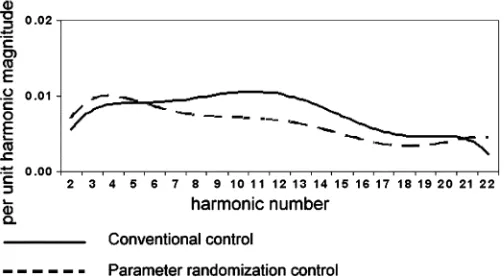
[image:7.594.305.553.477.603.2]Fig. 18. Comparison of harmonic profile at parallel inverter system output, when controlled via conventional control and randomized control techniques.
a lower level of THD is observed. With the results shown, the av-erage recorded THD measured by the power analyzer is 4.41%. This marks an appreciable improvement in the harmonic content of the parallel inverter output current, as compared to the re-sults obtained with conventional current control. The harmonic improvement is shown more clearly in Fig. 18. The current har-monic content at the parallel inverter system output is distinctly less when controlled via the randomized control technique. In the particular result presented in Fig. 18, the magnitude of the third harmonic is actually greater than that produced by the con-ventional controller. This simply reflects the behavior of the controller at the instant when the result was taken. Due to the time varying nature of the parameter randomization controller, the third harmonic may be lower at a different measuring in-stant and a different harmonic could appear to increase in mag-nitude. On average, however, a lower level of THD will still be observed.
IV. CONCLUSION
In multiple grid connected inverter systems, there tends to be a high degree of correlation in the harmonic profile of each indi-vidual inverter. These harmonics, therefore, tend to be additive at the system output. Hence, the parallel inverter system output yields a harmonic spectrum, and thus THD level, which is very similar to each individual inverter unit. This paper has proposed a method of eliminating the correlation in the harmonic profile of each inverter without the need for inter-inverter communica-tion. This has been achieved by means of randomising a tuning parameter of the current controller. The addition of a randomly varying component in the current control of each inverter has been shown to produce a harmonic output spectrum that varies with time and is uncorrelated to any other inverter in the system. By making the harmonic profile of each inverter different, the harmonics at the parallel inverter system output undergo a de-gree of cancellation, while the fundamental output remains the same. On average, this yields an improvement in the overall net THD of the system. In the case of the results shown, the THD is reduced from 5.44% to 4.41% representing an 18.9% improve-ment in THD performance. There is no cost in terms of ad-ditional system hardware required to achieve this reduction in
THD level. Furthermore, the harmonic cancellation algorithm is relatively straightforward to implement in software and does not significantly add to the overall processor execution time. In a practical grid connected system, there is likely to be signif-icantly more than three inverter units operating in parallel. By increasing the number of inverter units, the opportunity for har-monic cancellation improves. This should, theoretically, help to lower the overall THD level even further.
While primarily aimed toward grid connected inverter sys-tems, the technique proposed is equally applicable to any par-allel inverter system exhibiting correlation in individual inverter harmonic performance.
REFERENCES
[1] H. Haeberlin, “Evolution of inverters for grid connected pv systems from 1989 to 2000,” inProc. 17th European Photovoltaic Solar Energy Conf., Munich, Germany, Oct. 22–26, 2001, pp. 426–430.
[2] IEEE working group on power system harmonics, “Power system har-monics: An overview,”IEEE Trans. Power Apparat. Syst., vol. PAS-102, no. 8, pp. 2455–2460, Aug. 1983.
[3] T. H. Ortmeyer, K. R. Chakravarthi, and A. A. Mahmoud, “The effects of power systems on power station equipment and loads,”IEEE Trans. Power Apparat. Syst., vol. PAS-104, no. 9, pp. 2555–2563, Sep. 1985. [4] J. S. Subjak, Jr., “Harmonics—Causes, effects, measurements, and
analysis: An update,”IEEE Trans. Ind. Applicat., vol. 26, no. 6, pp. 1034–1042, Nov./Dec. 1990.
[5] Recommended Practice for Utility Interface of Photovoltaic (PV) Sys-tems, IEEE Std. P929, Dec. 1998.
[6] Recommendations for the Connection of Single-Phase Inverter-Con-nected Photovoltaic (PV) Generators Up to 5 kVA to Public Distribution Networks, Engineering Recommendation Std. G77: 2000 Electricity Association UK, 2000.
[7] W. Enders, C. Halter, and P. Wurm, “Investigation of typical problems of PV-inverters,” inProc. 17th European Solar Energy Conf. Exhibition, Munich, Oct., 22–26 2001.
[8] A. Kempe and U. Schonwandt, “EMC Of PV-plants with line commu-tated inverters,” inProc. 25th IEEE Photovoltaic Specialists Conf., 1996, pp. 1343–1346.
[9] J. Stevens, “The issue of harmonic injection from utility integrated pho-tovoltaic systems: Part 1. The harmonic source,”IEEE Trans. Energy Conv., vol. 3, no. 3, pp. 507–510, Sep. 1988.
[10] , “The issue of harmonic injection from utility integrated photo-voltaic systems: Part 2. study results,”IEEE Trans. Energy Conv., vol. 3, no. 1, pp. 511–515, Sep. 1988.
[11] D. Cyganski, J. A. Orr, A. K. Chakravorti, A. E. Emanuel, E. M. Gu-lachenski, C. E. Root, and R. C. Bellemare, “Current and voltage har-monic measurements and modeling at the gardner photovoltaic project,”
IEEE Trans. Power Delivery, vol. 3, no. 3, pp. 800–809, Jan. 1989. [12] G. A. Vokas and A. V. Machias, “Harmonic voltages and currents on two
greek islands with photovoltaic stations: Study and field measurements,”
IEEE Trans. Energy Conv., vol. 10, no. 2, pp. 302–306, Jun. 1995. [13] D. G. Holmes and B. P. McGrath, “Opportunities for harmonic
cancel-lation with carrier based PWM for two-level and multilevel cascaded inverters,” inProc. IEEE 34th Annu. Industry Applications Conf., vol. 2, Mar. 1999, pp. 781–788.
[14] T. J. Liang, R. M. O’Connell, and R. G. Hoft, “Inverter harmonic reduc-tion using Walsh funcreduc-tion Harmonic eliminareduc-tion method,”IEEE Trans. Power Electron., vol. 12, no. 6, pp. 971–982, Nov. 1997.
[15] D. G. Infield, “Combined switching harmonics from multiple grid-con-nected single phase inverters,”Proc. Inst. Elect. Eng., vol. 148, no. 5, pp. 427–430, Sep. 2001.
[16] A. D. Simmons and D. G. Infield, “Current waveform quality from grid-connected photovoltaic inverters and its dependence on operating con-ditions,”Progress Photovoltaics: Res. Applicat., pp. 411–420, 2000. [17] D. Gallo, R. Langella, and A. Testa, “On the processing of harmonic
892 IEEE TRANSACTIONS ON POWER ELECTRONICS, VOL. 20, NO. 4, JULY 2005
Matthew Armstrong received the M.Eng. degree from the University of Newcastle upon Tyne, New-castle upon Tyne, U.K., in 1998.
Since then he has worked as a Research As-sociate within the Power Electronics, Drives, and Machines Group, School of Electrical, Electronic and Computer Engineering, University of Newcastle upon Tyne. His main research interests are in power electronics, inverter control, and power quality improvement of utility connected inverter systems.
David J Atkinsonreceived B.Sc. and Ph.D. degrees in electrical and electronic engineering from the University of Newcastle upon Tyne, Newcastle upon Tyne, U.K., in 1978 and 1991, respectively.
He is currently a Senior Lecturer in the Drives, Power Electronics and Machines Group, Department of Electrical and Electronic Engineering, University of Newcastle upon Tyne. Prior to his university appointment He spent 17 years in the electronics industry including periods with NEI Electronics and British Gas Corporation. His research interests include electrical drive systems, real time estimation and control, power electronics, wind, and solar energy.
C. Mark Johnson(S’89–M’91) received the B.A. degree in engineering and the Ph.D. degree in elec-trical engineering from the University of Cambridge, London, U.K., in 1986 and 1991, respectively.
From 1990 to 1992, he was a Research Associate at the University of Cambridge, investigating GTO thyristors for traction applications. In 1992 he was appointed Lecturer at the University of Newcastle upon Tyne, Newcastle upon Tyne, U.K., where his research included the design, analysis, and charac-terization of power semiconductor devices, resonant power conversion and instrumentation. From 1998 to 2001, he managed to U.K. national programme on silicon carbide electronics and in 2000 he became Reader of Power Electronics at the University of Newcastle. In 2003, he was appointed Research Professor of Power Electronic Systems, Electrical Ma-chines and Drives Research Group, University of Sheffield, Sheffield, U.K. He continues to research power semiconductor devices, power device packaging, power module technologies, and power electronic applications. His specialist interests include power electronics for hostile environments and the thermal and electromagnetic management of power electronic systems.
Tusitha D. Abeyasekerareceived the M.Sc. degree (with honors) in electromechanical engineering from Kiev Polytechnic Institute, Kiev, Ukraine, in 1999 and is currently pursuing the Ph.D. degree in power quality improvements for grid connected PV inverters at the University of Newcastle upon Tyne, Newcastle upon Tyne, U.K.