s o l u t i o n s @ s y n g r e s s . c o m
Over the last few years, Syngress has published many best-selling and critically acclaimed books, including Tom Shinder’s Configuring ISA Server 2000, Brian Caswell and Jay Beale’s Snort 2.0 Intrusion Detection, and Angela Orebaugh and Gilbert Ramirez’s Ethereal
Packet Sniffing. One of the reasons for the success of these books has been our unique [email protected] program. Through this site, we’ve been able to provide readers a real time extension to the printed book.
As a registered owner of this book, you will qualify for free access to our members-only [email protected] program. Once you have registered, you will enjoy several benefits, including:
■ Four downloadable e-booklets on topics related to the book. Each booklet is approximately 20-30 pages in Adobe PDF format. They have been selected by our editors from other best-selling Syngress books as providing topic coverage that is directly related to the coverage in this book.
■ A comprehensive FAQ page that consolidates all of the key points of this book into an easy to search web page, pro-viding you with the concise, easy to access data you need to perform your job.
■ A “From the Author” Forum that allows the authors of this book to post timely updates links to related sites, or addi-tional topic coverage that may have been requested by readers.
Just visit us at www.syngress.com/solutions and follow the simple registration process. You will need to have this book with you when you register.
Thank you for giving us the opportunity to serve your needs. And be sure to let us know if there is anything else we can do to make your job easier.
Configuring
Rob Cameron NSA JNCIA-FWV
Christopher Cantrell NS-IDP
Dave Killion NSCA, NSCP
Kevin Russell JNCIS-FWV
NetScreen
®
Syngress Publishing, Inc., the author(s), and any person or firm involved in the writing, editing, or produc-tion (collectively “Makers”) of this book (“the Work”) do not guarantee or warrant the results to be obtained from the Work.
There is no guarantee of any kind, expressed or implied, regarding the Work or its contents.The Work is sold AS IS and WITHOUT WARRANTY.You may have other legal rights, which vary from state to state.
In no event will Makers be liable to you for damages, including any loss of profits, lost savings, or other incidental or consequential damages arising out from the Work or its contents. Because some states do not allow the exclusion or limitation of liability for consequential or incidental damages, the above limitation may not apply to you.
You should always use reasonable care, including backup and other appropriate precautions, when working with computers, networks, data, and files.
Syngress Media®, Syngress®, “Career Advancement Through Skill Enhancement®,” “Ask the Author UPDATE®,” and “Hack Proofing®,” are registered trademarks of Syngress Publishing, Inc. “Syngress:The Definition of a Serious Security Library”™, “Mission Critical™,” and “The Only Way to Stop a Hacker is to Think Like One™” are trademarks of Syngress Publishing, Inc. Brands and product names mentioned in this book are trademarks or service marks of their respective companies.
KEY SERIAL NUMBER 001 HJIRTCV764 002 PO9873D5FG 003 829KM8NJH2 004 KLNM56332B 005 CVPLQ6WQ23 006 VBP965T5T5 007 HJJJ863WD3E 008 2987GVTWMK 009 629MP5SDJT 010 IMWQ295T6T PUBLISHED BY Syngress Publishing, Inc. 800 Hingham Street Rockland, MA 02370
Configuring NetScreen Firewalls
Copyright © 2005 by Syngress Publishing, Inc. All rights reserved. Printed in the United States of America. Except as permitted under the Copyright Act of 1976, no part of this publication may be repro-duced or distributed in any form or by any means, or stored in a database or retrieval system, without the prior written permission of the publisher, with the exception that the program listings may be entered, stored, and executed in a computer system, but they may not be reproduced for publication.
Printed in the United States of America 1 2 3 4 5 6 7 8 9 0
ISBN: 1-932266-39-9
Publisher: Andrew Williams Page Layout and Art: Patricia Lupien Acquisitions Editor: Jaime Quigley Copy Editor: Amy Thomson Technical Editor: C.J. Cui and Thomas Byrne Indexer: Odessa&Cie Cover Designer: Michael Kavish
Acknowledgments
v
Syngress would like to acknowledge the following people for their kindness and support in making this book possible.
Syngress books are now distributed in the United States and Canada by O’Reilly Media, Inc.The enthusiasm and work ethic at O’Reilly is incredible and we would like to thank everyone there for their time and efforts to bring Syngress books to market:Tim O’Reilly, Laura Baldwin, Mark Brokering, Mike Leonard, Donna Selenko, Bonnie Sheehan, Cindy Davis, Grant Kikkert, Opol Matsutaro, Steve Hazelwood, Mark Wilson, Rick Brown, Leslie Becker, Jill Lothrop,Tim Hinton, Kyle Hart, Sara Winge, C. J. Rayhill, Peter Pardo, Leslie Crandell, Valerie Dow, Regina Aggio, Pascal Honscher, Preston Paull, Susan Thompson, Bruce Stewart, Laura Schmier, Sue Willing, Mark Jacobsen, Betsy Waliszewski, Dawn Mann, Kathryn Barrett, John Chodacki, and Rob Bullington. And a hearty wel-come to Aileen Berg—glad to be working with you.
The incredibly hard working team at Elsevier Science, including Jonathan Bunkell, Ian Seager, Duncan Enright, David Burton, Rosanna Ramacciotti, Robert Fairbrother, Miguel Sanchez, Klaus Beran, Emma Wyatt, Rosie Moss, Chris Hossack, Mark Hunt, and Krista Leppiko, for making certain that our vision remains worldwide in scope.
David Buckland, Marie Chieng, Lucy Chong, Leslie Lim, Audrey Gan, Pang Ai Hua, and Joseph Chan of STP Distributors for the enthusiasm with which they receive our books.
Kwon Sung June at Acorn Publishing for his support.
David Scott,Tricia Wilden, Marilla Burgess, Annette Scott, Andrew Swaffer, Stephen O’Donoghue, Bec Lowe, and Mark Langley of Woodslane for dis-tributing our books throughout Australia, New Zealand, Papua New Guinea, Fiji Tonga, Solomon Islands, and the Cook Islands.
vii
Lead Author
Rob Cameron (CCSA, CCSE, CCSE+, NSA, JNCIA-FWV, CCSP, CCNA, INFOSEC, RSA SecurID CSE) is an IT consultant who has worked with over 200 companies to provide network secu-rity planning and implementation services. He has spent the last five years focusing on network infrastructure and extranet security. His strengths include Juniper’s NetScreen Firewall products,
NetScreen SSL VPN Solutions, Check Point Firewalls, the Nokia IP appliance series, Linux, Cisco routers, Cisco switches, and Cisco PIX firewalls. Rob strongly appreciates his wife Kristen’s constant sup-port of his career endeavors. He wants to thank her for all of her support through this project.
C.J. Cui (CISSP, JNCIA) is Director of Professional Services for NetWorks Group, an information security consulting company headquartered in Brighton, Michigan. NetWorks Group provides information security solutions that mitigate risk while enabling secure online business. C.J. leads the technical team at NetWorks Group to deliver information security services to customers ranging from medium-sized companies to fortune 500 corporations.These services touch every part of security lifecycle—from enterprise security management, security assessment and audit to solution design and implementation—and leverage leading edge technologies including firewall/VPN, intrusion prevention, vulnerability manage-ment, malicious code protection, identity management and forensics analysis. C.J. holds an M.S. degree from Michigan State University and numerous industrial certifications. He is a board member of ISSA Motor City Chapter and serves as the Director of Operations for the chapter.
viii
Thomas Byrne is a Code Monkey with NetScreen Technologies (now Juniper Networks). He currently does design, planning, and implementation on Juniper’s Security Manager, their next-genera-tion network management software.Tom’s background includes positions as a UI Architect at ePatterns, and as a senior developer and consultant for several Silicon Valley companies, including Lightsocket.com and Abovenet.Tom is an active developer on sev-eral open-source projects and a voracious contributor to sevsev-eral on-line technology forums.Tom currently lives in Silicon Valley with his wife Kelly, and children, Caitlin and Christian.
Dave Killion (NSCA, NSCP) is a senior security research engineer with Juniper Networks, Inc. Formerly with the U.S. Army’s
Information Operations Task Force as an Information Warfare Specialist, he currently researches, develops, and releases signatures for the NetScreen Deep Inspection and Intrusion Detection and Prevention platforms. Dave has also presented at several security conventions including DefCon and ToorCon, with a proof-of-con-cept network monitoring evasion device in affiliation with several local security interest groups that he helped form. Dave lives south of Silicon Valley with his wife Dawn and two children, Rebecca and Justin.
Kevin Russell ( JNCIA-FWV, JNCIA-IDP) is a system engineer for Juniper Networks, specializing in firewalls, IPSEC, and intrusion detection and prevention systems. His background includes security auditing, implementation, and design. Kevin lives in Michigan with his wife and two children.
ix
Chris Cantrell(NetScreen IDP) is a Director of System
Engineering – Central Region for the Security Products Group at Juniper Networks. His career has spanned over 12 years, the last 8 focused in network and application security. Chris joined
OneSecure in late 2000 where he was an active member of the team who designed and was responsible for the introduction of their intrusion prevention product, the IDP. In 2002, OneSecure was acquired by NetScreen Technologies and most recently acquired by Juniper Networks where Chris continues to manage their security sales engineering team for the Central Region. Chris attended Auburn University at Montgomery where his focus was on business and management information systems. Chris lives in Denver,
Colorado with his wife Maria and two children, Dylan and Nikki.
x
Johny Mattsson (NCSA, NCSP, SCJP, SCJD) is a senior engineer in Ericsson Australia’s IP Centre, where he has been working with NetScreen firewalls for over three years.The Ericsson IP Centre provides global integration and support services for a wide range of IP based telecommunications solutions, including DSL broadband and 3G IP Multimedia Sub-systems (IMS). Johny’s main areas of specialization are IP network security and several cutting edge 3G mobile services built on IMS. In addition to making sure things are always working on the technical plane, he is the main interface towards Juniper/NetScreen, working to ensure that the support channels are functioning optimally. Before taking up the role in the Ericsson IP Centre, Johny worked as a system designer for Ericsson in Sweden.There he was involved in the design and implementation of various real-time telecommunications applications, often with a focus on the security aspects. Johny would like to thank Greg Bunt at Juniper/NetScreen, for the many late nights he has spent helping resolve last minute issues, instead of spending time with his family.
xi
Ralph Bonnell (CISSP, LPIC-2, CCSI, CCNA, MCSE: Security) is a senior information security consultant at Accuvant in Denver, Colorado. His primary responsibilities include the deployment of various network security products and product training. His spe-cialties include NetScreen deployments, Linux client and server deployments, Check Point training, firewall clustering, and PHP web programming. Ralph also runs a Linux consulting firm called Linux Friendly. Before moving to Colorado, Ralph was a senior security engineer and instructor at Mission Critical Systems, a Gold Check Point partner and training center in South Florida.
xiii
Contents
Foreword . . . .xxxi
Chapter 1 Networking, Security, and the Firewall . . . . .1
Introduction . . . .2
Understanding Networking . . . .3
The OSI Model . . . .3
Layer 7:The Application Layer . . . .4
Layer 6:The Presentation Layer . . . .5
Layer 5:The Session Layer . . . .5
Layer 4:The Transport Layer . . . .5
Layer 3:The Network Layer . . . .6
Layer 2:The Data Link Layer . . . .6
Layer 1:The Physical Layer . . . .6
Moving Data Along with TCP/IP . . . .6
Understanding IP . . . .7
IP Packets . . . .9
What Does an IP Address Look Like? . . . .12
IP Address Allocation . . . .13
NAT and Private IP Addresses . . . .14
TCP Communications . . . .14
UDP Communications . . . .16
What is a Port? . . . .16
Data Link Layer Communication . . . .17
Understanding Security Basics . . . .19
The Need For Security . . . .20
Introducing Common Security Standards . . . .20
Common Information Security Concepts . . . .21
Defining Information Security . . . .22
Identifying Potential Threats . . . .27
Using VPNs in Today’s Enterprise . . . .27
The Battle for the Secure Enterprise . . . .28
Making Your Security Come Together . . . .30
Understanding Firewall Basics . . . .30
Types of Firewalls . . . .30
Packet Filters . . . .31
Application Proxy . . . .32
Stateful Inspection . . . .32
Firewall Incarnate . . . .33
Firewall Ideologies . . . .34
DMZ Concepts . . . .34
Traffic Flow Concepts . . . .39
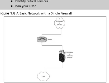
Networks with and without DMZs . . . .43
Pros and Cons of DMZ Basic Designs . . . .44
DMZ Design Fundamentals . . . .46
Why Design Is So Important . . . .47
Designing End-to-End Security for Data Transmission Between Hosts on the Network . . . .48
Traffic Flow and Protocol Fundamentals . . . .48
Summary . . . .50
Solutions Fast Track . . . .50
Frequently Asked Questions . . . .51
Chapter 2 Dissecting the NetScreen Firewall . . . .55
Introduction . . . .56
The NetScreen Security Product Offerings . . . .57
Firewalls . . . .58
SSL VPN . . . .59
IDP . . . .61
The NetScreen Firewall Core Technologies . . . .63
Zones . . . .63
Virtual Routers . . . .64
Interface Modes . . . .64
Policies . . . .65
VPN . . . .66
Device Architecture . . . .68
The NetScreen Firewall Product Line . . . .70
Product Line . . . .70
NetScreen-Remote Client . . . .72
Small Office Home Office . . . .73
Mid-Range . . . .77
High-Range . . . .79
Enterprise Class . . . .83
Next Generation Enterprise Class . . . .85
Carrier Class . . . .87
Enterprise Management . . . .89
Summary . . . .91
Solutions Fast Track . . . .92
Frequently Asked Questions . . . .94
Chapter 3 Deploying NetScreen Firewalls . . . .97
Introduction . . . .98
Managing the NetScreen Firewall . . . .98
NetScreen Management Options . . . .99
Serial Console . . . .99
Telnet . . . .100
Secure Shell . . . .100
WebUI . . . .101
The NetScreen-Security Manager . . . .102
Administrative Users . . . .102
The Local File System and the Configuration File . . . .104
Using the Command Line Interface . . . .108
Using the Web User Interface . . . .113
Securing the Management Interface . . . .114
Updating ScreenOS . . . .130
System Recovery . . . .131
Configuring the NetScreen Firewall . . . .134
Types of Zones . . . .135
Security Zones . . . .135
Tunnel Zones . . . .136
Function Zones . . . .136
Types of Interfaces . . . .137
Security Zone Interfaces . . . .137
Function Zone Interfaces . . . .139
Tunnel Interfaces . . . .140
Loopback Interfaces . . . .140
Configuring Security Zones . . . .140
Configuring Your NetScreen for the Network . . . .146
Binding an Interface to a Zone . . . .147
Setting up IP Addressing . . . .148
Configuring the DHCP Client . . . .148
Using PPPoE . . . .149
Interface Speed Modes . . . .150
Port Mode Configuration . . . .151
Configuring Basic Network Routing . . . .153
Configuring System Services . . . .157
Setting The Time . . . .157
DHCP Server . . . .159
DNS . . . .163
SNMP . . . .164
Syslog . . . .167
WebTrends . . . .168
Resources . . . .169
Summary . . . .170
Solutions Fast Track . . . .171
Frequently Asked Questions . . . .172
Chapter 4 Policy Configuration . . . .175
Introduction . . . .176
NetScreen Policies . . . .176
Theory Of Access Control . . . .179
Types of NetScreen Policies . . . .180
Intrazone Policies . . . .181
Interzone Policies . . . .182
Global Policies . . . .182
Default Policy . . . .182
Policy Checking . . . .183
Policy Components . . . .186
Zones . . . .186
Address Book Entries . . . .187
Creating Address Book Entries . . . .187
Modifying and Deleting Address Book Entries . . . .190
Address Groups . . . .190
Services . . . .192
Creating Custom Services . . . .192
Modifying and Deleting Services . . . .194
Service Groups . . . .195
Creating Policies . . . .196
Creating a Policy . . . .196
Creating a Policy via the WebUI . . . .197
Reordering Policies in the WebUI . . . .200
Other Policy Options in the WebUI . . . .203
Creating a Policy via the CLI . . . .203
Other Policy Options Available in the CLI . . . .208
Summary . . . .209
Solutions Fast Track . . . .210
Frequently Asked Questions . . . .211
Chapter 5 Advanced Policy Configuration . . . .213
Introduction . . . .214
Network Traffic Management . . . .214
The Benefits of Traffic Shaping . . . .215
Packet Queuing . . . .216
Guaranteed Bandwidth . . . .217
Traffic Shaping Examples . . . .221
Traffic Shaping Example 1 . . . .221
Traffic Shaping Example 2 . . . .222
Configuring Traffic Shaping . . . .225
Interface Bandwidth . . . .225
Policy Configuration . . . .227
Advanced Policy Options . . . .229
Counting . . . .230
Configuring Counting . . . .233
Scheduling . . . .237
Configuring Scheduling . . . .238
Authentication . . . .241
Configuring Authentication . . . .242
Summary . . . .250
Solutions Fast Track . . . .250
Frequently Asked Questions . . . .252
Chapter 6 User Authentication . . . .255
Introduction . . . .256
Types of Users . . . .256
Uses of Each Type . . . .256
Auth Users . . . .257
IKE Users . . . .258
L2TP Users . . . .259
XAuth Users . . . .260
Admin Users . . . .260
User Databases . . . .260
Local Database . . . .260
Types of Users . . . .261
Features . . . .261
External Auth Servers . . . .261
Object Properties . . . .262
Auth Server Types . . . .263
RADIUS . . . .263
SecurID . . . .265
LDAP . . . .267
Default Auth Servers . . . .270
How to Change . . . .270
When to Use . . . .271
Authentication Types . . . .271
Auth Users and User Groups . . . .272
IKE Users and User Groups . . . .273
XAuth Users and User Groups . . . .274
L2TP Users and User Groups . . . .276
Admin Users and User Groups . . . .278
User Groups and Group Expressions . . . .279
Summary . . . .281
Solutions Fast Track . . . .281
Frequently Asked Questions . . . .282
Chapter 7 Routing . . . .285
Introduction . . . .286
Virtual Routers . . . .286
Using Virtual Routers . . . .287
Creating Virtual Routers . . . .287
Route Selection . . . .288
Set Route Preference . . . .289
Set Route Metric . . . .291
Route Redistribution . . . .293
Configuring a Route Access List . . . .294
Configuring A Route Map . . . .295
Routing Information Protocol . . . .297
RIP Concepts . . . .297
Basic RIP Configuration . . . .297
Configuring RIP . . . .298
Open Shortest Path First (OSPF) . . . .302
OSPF Concepts . . . .302
Basic OSPF Configuration . . . .303
Border Gateway Protocol . . . .308
Basic BGP Configuration . . . .308
Summary . . . .314
Solutions Fast Track . . . .314
Frequently Asked Questions . . . .316
Chapter 8 Address Translation . . . .317
Introduction . . . .318
Purpose of Address Translation . . . .318
Advantages of Address Translation . . . .318
Disadvantages of Address Translation . . . .321
NetScreen NAT Overview . . . .321
NetScreen Packet Flow . . . .322
Interface-based Source Translation . . . .325
MIP . . . .326
MIP Limitations . . . .326
MIP Scenarios . . . .327
Policy-based Source NAT . . . .331
DIP . . . .333
Destination NAT . . . .338
VIP . . . .338
Policy-based Destination NAT . . . .340
Destination NAT Scenarios . . . .341
Destination PAT Scenario . . . .345
Source and Destination NAT Combined . . . .346
Summary . . . .347
Solutions Fast Track . . . .348
Links to Sites . . . .350
Frequently Asked Questions . . . .350
Chapter 9 Transparent Mode . . . .353
Introduction . . . .354
Interface Modes . . . .354
NAT Mode . . . .354
Route Mode . . . .355
Understanding How Transparent Mode Works . . . .356
How to Transparent Mode Works . . . .356
Layer 2 Zones . . . .357
VLAN Zone . . . .357
Broadcast Methods . . . .357
Configuring a Device to Use Transparent Mode . . . . .358
VLAN1 Interface . . . .359
Converting an Interface to Transparent Mode . . . .361
Creating a Custom Layer 2 Zone and Network Object 363 Transparent Mode Deployment Options . . . .363
Network Segmentation . . . .363
VPNs with Transparent Mode . . . .369
Summary . . . .376
Solutions Fast Track . . . .376
Chapter 10 Attack Detection and Defense . . . .379 Introduction to the ScreenOS Security Features . . . .380 Understanding the Anatomy of an Attack . . . .380 The Three Phases of a Hack . . . .381 Script Kiddies . . . .381 Black Hat Hackers . . . .383 Worms, Viruses, and other Automated Malware . . . .385 Configuring SCREEN Settings . . . .388 Reconnaissance Detection . . . .389 Port Scans and Sweeps . . . .389 TCP Protocol Manipulation . . . .390 IP Protocol Manipulation . . . .390 Flood Attacks . . . .391 Protocol Attacks . . . .393 Applying Deep Inspection . . . .394 Getting the Database . . . .396 Configuring the Firewall for Automatic DI Updates 397 Loading the Database Manually . . . .398 Using Attack Objects . . . .399 Using Attack Groups . . . .400 Enabling Deep Inspection with a Policy using
the WebUI . . . .400 Enabling Deep Inspection with a Policy using
the CLI . . . .402 Explanation of Deep Inspection Contexts and
Activating Antivirus Scanning . . . .426 Understanding Application Layer Gateways . . . .427 Applying Best Practices . . . .429 Defense-In-Depth . . . .429 Zone Isolation . . . .429 Egress Filtering . . . .430 Explicit Permits, Implicit Denies . . . .430 Retain Monitoring Data . . . .430 Keep Systems Updated . . . .431 Summary . . . .432 Solutions Fast Track . . . .433 Frequently Asked Questions . . . .436
Gateway Redundancy . . . .467 Back-to-Back VPNs . . . .468 Hub and Spoke VPNs . . . .468 Multi-tunnel Interfaces . . . .469 Solutions Fast Track . . . .470 Links to Sites . . . .473 Mailing Lists . . . .473 Frequently Asked Questions . . . .474
Chapter 12 Virtual Systems . . . .475 Introduction . . . .476 What Is a Virtual System? . . . .476 Virtual System Components . . . .477 How Virtual Systems Work . . . .478 Classifying Traffic . . . .478 VLAN-Based Classification . . . .479 IP-Based Classification . . . .479 Virtual System Administration . . . .479 Configuring Virtual Systems . . . .480 Creating a Virtual System . . . .480 Network Interfaces . . . .483 Physical Interfaces . . . .483 Subinterfaces . . . .485 Shared Interface . . . .487 Summary . . . .491 Solutions Fast Track . . . .491 Frequently Asked Questions . . . .492
Chapter 13 High Availability . . . .495 Introduction . . . .496 The Need for High Availability . . . .496 Improving Availability Using NetScreen SOHO Appliances 498 Failing Over Between Interfaces . . . .498 Using Dual Untrust Interfaces to Provide Redundancy 499 Example: Configuration for Dual ADSL Modems . .500 Example: Advanced Configuration for ADSL
Falling Back to Dial-up . . . .504 Example: A Simple Backup Dial-up Configuration .505 Example: An Advanced Backup Dial-up
Configuration . . . .506 Restricting Policies to a Subset When Using the
Serial Interface . . . .509 Example: Marking FTP as Not Allowed When
Using the Serial Interface . . . .509 Using IP Tracking to Determine Failover . . . .510 Example:Tracking the Default Gateway . . . .511 Example: A More Complex IP Tracking Scenario . .512 Monitoring VPNs to Determine Failover . . . .513
Example: Monitoring One VPN Tunnel, with
Example: Setting Both Cluster ID and Cluster Name 531 Synchronizing the Configuration . . . .531 Initial Synchronization Procedure #1 . . . .532 Initial Synchronization Procedure #2 . . . .534 Determining When to Failover – The NSRP Ways . . . .535 Using NSRP Heartbeats . . . .536 Example: Configuring More Aggressive Heartbeats .537 Using Optional NSRP Monitoring . . . .537 Example: Lowering the Failover Threshold . . . .538 Using NSRP Interface Monitoring . . . .539 Example: A Simple Interface Monitoring Setup . . .539 Example: A More Complex Interface
Monitoring Setup . . . .539 Using NSRP Zone Monitoring . . . .540 Example: Monitoring the Untrust Zone . . . .541 Example: Using Combined Interface and
Zone Monitoring . . . .541 Using NSRP IP Tracking . . . .542
Example: Using IP Tracking to Determine
VPN Availability . . . .544 Example: Combining Interface, Zone, and IP
Tracking Monitoring . . . .546 Reading the Output from “get nsrp” . . . .550 Looking into an NSRP Cluster . . . .550 Example: NS-500 Firewall and NSEP cluster . . . . .551 Using NSRP-Lite on Mid-range Appliances . . . .555 Basic NSRP-Lite Usage . . . .555 Example: Providing HA Internet Access . . . .556 Working with Local Interfaces in an NSRP-Lite Setup 560 Example: HA Internet via Dual Providers . . . .560 Creating Redundant Interfaces . . . .566
Grouping Physical Interfaces Into a Redundant
Interface . . . .567 Example: A Simple Redundant Interface Setup . . . .567 Example: Changing the Primary Interface of a
Taking Advantage of the Full NSRP . . . .569 Synchronizing State Using RTO Mirroring . . . .570
Example: Enabling RTO Mirroring in an NSRP
Cluster . . . .570 Example: Preventing Certain Sessions from
Being Backed Up . . . .570 Setting Up an Active/Active Cluster . . . .571 Example: A Typical Active/Active Setup . . . .573 Implementing a Full-mesh Active/Active Setup . . . . .579 Example: A Full-mesh Active/Active Setup . . . .579 Failing Over . . . .586
Example: Adjusting the Numberof ARP Packets
Sent After Failover . . . .587 Failing Over Virtual Systems . . . .588 Example: Binding a VSYS to VSD Group 1 . . . .588 Avoiding the Split-brain Problem . . . .589 Example: Configuring a Secondary NSRP Path . . .591 Avoiding the No-brain Problem . . . .591 Summary . . . .594 Solutions Fast Track . . . .595 Frequently Asked Questions . . . .599
Get Route . . . .609 Get Interface . . . .609 Get ARP . . . .610 Get System . . . .611 Debug . . . .611 Snoop . . . .612 Putting It All Together . . . .613 Network Troubleshooting . . . .613 Debugging the NetScreen Device . . . .613 Debugging NAT . . . .616 Debugging VPNs . . . .617 Policy-based VPN . . . .618 Route-based VPN . . . .619 Debugging NSRP . . . .619 Debugging Traffic Shaping . . . .620 NetScreen Logging . . . .621 Traffic . . . .622 Self . . . .622 Event . . . .622 Summary . . . .623 Solutions Fast Track . . . .623 Frequently Asked Questions . . . .626
Creating VPNs . . . .666 Summary . . . .671 Solutions Fast Track . . . .671 Frequently Asked Questions . . . .672
Appendix A ScreenOS 5.1.0 Enhancements and
New Features . . . .675 Copyright © Juniper Networks
Reprinted with the consent of Juniper Networks Authored by Finina Aranez
Introduction . . . .676 New Features in ScreenOS 5.1.0 . . . .676 Attack Protection . . . .677 Deep Inspection Enhancements . . . .677 Antivirus . . . .677 TCP Reset . . . .677 Authentication . . . .677 Extra Banner . . . .677 WebAuth via SSL Only . . . .678 Self-Signed Certificates . . . .678 DHCP for VoIP . . . .678 DIP . . . .678 Domin Name Service . . . .678 Dynamic DNS . . . .678 Proxy DNS . . . .679 Interfaces . . . .679 MTU on Tunnel Interface . . . .679 Generic Routing Encapsulation (GRE) . . . .679 Layer 2 Transport Protocol . . . .679
Outgoing Dialup Policy for L2TP and L2TP
NetScreen Redundancy Protocol - NSRP . . . .680 Interface Monitoring . . . .680 NSRP Active/Active enhancements . . . .680 Policies . . . .681 New Policy Action – Reject . . . .681 Port Modes . . . .681 DMZ/Dual Untrust Port Mode . . . .681 Point to Point Protocol over Ethernet . . . .681 Multiple PPPoE Sessions Over a Single Interface . .681 PPPoE and NSRP . . . .681 Routing . . . .682 Equal Cost Multi Path (ECMP) . . . .682 Source Interface-Based Routing (SIBR) and
Source-Based Routing (SBR) . . . .682 BGP Enhancements . . . .682 OSPF Enhancements . . . .682 RIP Enhancements . . . .682 Multicast Routing . . . .683 Services . . . .683
Sun RPC ALG—Remote Procedure Call
Application Layer Gateway . . . .683 Microsoft RPC ALG—Remote Procedure Call
Application Layer Gateway . . . .683 RTSP ALG—Real Time Streaming Protocol
Appendix B Certification
A complimentary chapter on NetScreen Certification is available from the Syngress Solutions site
(www.syngress.com/solutions).
You’re at home, you’ve just gotten your first broadband connection, and your computer is hardwired to the Internet.You boot up your computer, and imme-diately some pit-bull of a virus starts attacking your PC. Or, you go to work, where your (clueless?) IT directory proudly shows off the new HRH brand firewall he’s somehow installed between the server and the Cuisinart in the kitchen.You send some e-mail to a co-worker in a remote location, and a hacker with a God complex decides to read it, gets some critical information and ruins your next product release. How about this? You’re in charge of your corporation’s website running 24/7 and your firewall fails while you’re fast asleep, causing thousands or millions of dollars in lost revenue.
These may sound silly, but unfortunately they happen every day. (Well, maybe not the Cuisinart one...) And the thing that most people don’t realize is that they’re all preventable.With some careful planning and the right equip-ment, you can avoid all of these scenarios.
A proper product can provide you security, management, high availability, secure VPN’s and much more, all with reliability and scalability. If you’ve bought this book, I think it’s safe to assume that you either: a) own a
NetScreen device, or b) are considering using one. Either choice shows excel-lent judgment, given that NetScreen is a proven, award-winning platform that can provide you with all of the above services, and do it very well.
This book will give you the information to install, configure and manage your NetScreen firewalls, whether you are planning to install a single device at your house, or roll out hundreds or thousands of devices into your worldwide network.You will find a lot of information about concepts and implementation of virtually all of the NetScreen’s capabilities, enabling you to not just use these amazing devices, but to use all of their abilities to best suit your needs.
xxxi
This book will cut right to the center of essential functionalities and tell you how to plan for the unexpected, and how to deal with almost all of the pressing issues that confront any IT professional that needs a comprehensive security solution.Whether you are implementing large scale VPN’s, an NSRP Cluster, complex routing scenarios or more simplistic Policy based Security and IDP management and logging, you will find concise information enabling you to do so.
This book won’t do everything, however. It won’t waste your time with unnecessary details. It won’t bore you with unneeded information, and it won’t let you go until you realize that you can have a secure network, quickly and easily, and that you can have it all in one package, a nice blue package with the NetScreen logo on it.
Networking,
Security, and the
Firewall
Solutions in this Chapter:
■ Understanding Networking
■ Understanding Security Basics
■ Understanding Firewall Basics
Chapter 1
1
Summary
Solutions Fast Track
Introduction
Every enterprise requires at least one firewall to provide the backbone for its net-work security architecture. Firewalls are the core component of your netnet-work’s security.The risks today have greatly increased, so the call for a stronger breed of firewall has been made. In the past, simple packet filtering firewalls allowing access to your internal resources have helped to mitigate your network’s risk.The next development was stateful inspection allowing you to monitor network ses-sions instead of single packets.Today’s risks are far greater and require a new gen-eration of devices to help secure our networks’ borders from the more
sophisticated attacks.
Firewalls police your network traffic. A firewall is a specialized device that allows or denies traffic based upon administratively defined policies.They contain technologies to inspect your network’s traffic.This technology is not something that is exclusive to firewalls, but firewalls are designed specifically for inspecting traffic and therefore do it better then any other type of device. Any network can have millions of packets transverse it in a short period of time. It is impossible for a human to directly interact with the network. Even if you were to use a tool to look at the traffic directly it would be impossible for you to decide which traffic is good and which is bad.The need for a specialized device to enforce traffic restrictions has grown over the years. Because security is of such high impor-tance, a specialized device was required to ensure the security of network traffic.
NetScreen firewall appliances have answered this call for a secure enterprise. The NetScreen firewall product line has complete offerings from the home office to the carrier-class networks. In this chapter we will review networking basics. Security requires a strong basic knowledge of networking protocols. In our first section, “Understanding Networking,” we will look at networking from a top-down approach.This section starts with the basic ideas of networking models and then works into full networking communications. We will also discuss the components and prerequisites of IP addresses and how they are divided up to make networks.
most commonly used networking protocol and it is the protocol of the Internet. Finally in this chapter, we will look at network security.There are many impor-tant concepts to be aware of for information security.This will help you under-stand some network design considerations and the background behind them.
Understanding Networking
To understand networking is to understand the language of firewalls. A firewall is used to segment resources and limit access between networks. Before we can really focus on what a firewall does for us, we need to understand how net-working works.Today in most environments and on the Internet, the protocol suite TCP/IP (Transmission Control Protocol/Internet Protocol) is used to trans-port data from here to there. We will begin this chapter by looking at networking as a whole with a focus on the Open System Interconnection (OSI) model.
The OSI Model
The OSI model was originally developed as a framework to build networking protocols on. During the time when then Internet was being developed, a pro-tocol suite named TCP/IP was developed.TCP/IP was found to meet the requirements of the Internet’s precursor, ARPANET. At this point,TCP/IP was already integrated into UNIX and was quickly adopted by the academic commu-nity as well. With the advent of the Internet and its widespread usage,TCP/IP has become the de facto standard protocol suite of internetworking today.
The OSI model consists of seven distinct layers.These layers each contain the fundamental ideas of networking. In Figure 1.1 we can see the way that the seven layers stack on top of each other.The idea is that each upper layer is encapsulated inside of each lower layer. So ultimately, any data communications are transformed into the electrical impulses that pass over the cables or through the air that surrounds us. Understanding the OSI model is understanding the core of networking. In many places throughout this book, the OSI model is used to create a visual representation of networking.
The reality, however, is that the OSI model is just a reference model that pro-tocols are based upon.The next section, called “Moving Data Along With
website that talks about networking protocols references the OSI model. It is important to have a baseline when discussing every topic.
For example, let’s compare cars and trucks.They are effectively the same device. Both are used to get from here to there, but they are designed very differ-ently. A truck has a sturdier frame to allow it to tow heavy loads. A car is smaller and is designed to be a transport for people. While these devices are very dif-ferent, they still have common components.They both have wheels, doors, brakes, and engines.This is much like the different components of a network protocol, which is essentially a vehicle for data. Networking protocols have com-ponents to help get the data from here to there, like wheels.They have compo-nents to control the flow of data, like brakes.These are all requirements of any protocol. Using and understanding the OSI model makes protocol usage and design easier. Whether TCP/IP or IPX/SPX, most protocols are built around the same framework (model).
Figure 1.1 The 7-Layer OSI Model
7. Application Layer 6. Presentation Layer 5. Session Layer 4. Transport Layer 3. Network Layer 2. Data Link Layer 1. Physical Layer
Layer 7:The Application Layer
The application layer contains application data.This is the layer at which applica-tions communicate to one another.The reason for all of the other layers is essen-tially to transport the messages contained at the application layer. When
that was requested. All of this is an example of application layer communications. Other examples of application layer protocols are File Transfer Protocol (FTP), Domain Name Service (DNS),Telnet, and Secure Shell (SSH).
Layer 6:The Presentation Layer
The presentation layer controls the presentation or formatting of the data con-tent. At this point in the OSI model there is no data communications per se.The focus of this layer is having a common ground to present data between applica-tions. For example, let’s take image files. Billions of image files are transferred every day. Each of these files contains an image that ultimately will be displayed or stored on a computer. However, each image file must be the proper specified file format.This way, the application that reads the image file understands the type of data and the format that is contained in it. A JPEG file and a PNG file may contain the same image, but each uses a separate format. A JPEG file cannot be interpreted as a PNG and vice versa. Additionally, file-level encryption occurs at the presentation layer.
Layer 5:The Session Layer
The session layer controls sessions between two systems. It is important to have sessions, as it is the core of any communications for networking. If you did not have sessions, all communications would run together without any true idea of what is happening throughout the communication. As you will see below, TCP/IP has no session layer, really. In TCP/IP the session layer blends together with the transport layer. Other protocols such as NetBIOS, used on Microsoft networks, use the session layer for reliable communications.
Layer 4:The Transport Layer
Layer 3:The Network Layer
When packets have to get between two stations on a network, the network layer is responsible for the transportation of these packets.The network layer deter-mines the path and the direction on the network in order to allow communica-tions between two stacommunica-tions.The IP portion of TCP/IP rests in this part of the OSI model. IP is discussed in detail in the following section.
Layer 2:The Data Link Layer
Layer two, or the data link layer, is the mechanism that determines how to transmit data between two stations. All hosts that communicate at this level must be on the same physical network.The way in which the transmission of data at this level is handled is based upon the protocol used. Examples of protocols at the data link layer are Ethernet, Point-to-Point Protocol (PPP), Frame Relay, Synchronous Data Link Control (SDLC), and X.25. Protocols such as Address Resolution Protocol (ARP) function at the Data Link Layer.
Layer 1:The Physical Layer
The last but most important layer of the OSI model is the physical layer.The physical layer consists of the objects that connect stations together physically.This layer is responsible for taking the bits and bytes of the higher layers and passing them along the specified medium.There are many examples of the physical layer that you should already have heard of, such as Cat5 cable,T1, and wireless.
Moving Data Along with TCP/IP
On the Internet and most networks,TCP/IP is the most commonly used pro-tocol for passing network data. At the time of its development,TCP/IP used a very advanced design. Decades later,TCP/IP continues to meet the needs of the Internet.The most commonly used version of IP used today is version 4, the ver-sion covered in this book.The next generation IP, verver-sion 6, is starting to be used much more throughout the world. Many vendors, including Juniper Networks, Cisco, Microsoft, and Apple are developing software that support the new IP ver-sion 6 standard.
Datagram Protocol (UDP) and how they are used to control data communica-tions in conjunction with IP. Finally, we will wrap up the discussion of TCP/IP with information about the data link layer.
Understanding IP
The Internet Protocol (IP) is used to get data from one system to another.The IP protocol sits on the third layer of the OSI model, the network layer. When you need to send data across a network, that data is encapsulated in a packet. A packet is simply a segment of data that is sent across the network. In TCP/IP however, there are not seven true layers as there are in the OSI model (see Figure 1.2 for a comparison of TCP/IP and OSI model layers).
When an application needs to pass its communication to another system on the network, it passes its information down the protocol stack.This is the process that creates an IP packet.
Figure 1.2 OSI Model Layers Versus TCP/IP Layers
OSI Model TCP/IP Model
7. Application Layer
5. Application Layer 6. Presentation Layer
5. Session Layer 4. Transport Layer 4. Transport Layer
3. Network Layer 3. Network Layer 2. Data Link Layer 2. Data Link Layer 1. Physical Layer 1. Physical Layer
Lets look at an example of IP connectivity. We will be referencing the TCP/IP model, as it will be easier to understand for this example. Remember that the TCP/IP model is a condensed version of the OSI model. Use Figure 1.2 to reference the steps of the OSI model on the left to the TCP/IP model on the right.You can use your web browser to connect to www.syngress.com and view the series of events that occur during a network (in this case, the Internet) con-nection. We will look at the course of action that happens for the first packet that is created for this connection.
the transport layer where it initiates a session to the remote machine.To get to the remote machine, the transport layer sends its data to the network layer and creates a packet.The data link layer’s job is to get the packet across the local net-work. At this point, the packet is called a frame. At each junction point between systems and routing devices, the data link layer makes sure that the frame is prop-erly transmitted.The physical layer is used during the entire connection to con-vert the raw data into electrical or optical impulses.
When the end station receives the packet, that station will convert the packet back to the application layer.The electrical impulses are changed at the physical layer into the frame.The frame is then unencapsulated and converted to individual packets. Because the packet is at its end destination, the network layer and transport portions of the packet are removed and then the application data is passed to the application layer.That sounds like a lot of work for just one packet to transverse the Internet, but all of this happens on a broadband connection in 30 milliseconds or less.This, of course, is the simplified version of how all of this happens. In the following sections, we will expand on this example and show you what happens behind the scenes when two stations have a network conversation.
The following list provides a rundown of the phases of connectivity:
1. The URL www.syngress.com is entered into the browser.
2. The user presses Enter and forces the browser to connect to the web-site.
3. The browser makes a request to the server.
4. The browser request is handed to the transport layer.
5. The transport layer initiates a session to the remote server.
6. The transport layer passes its request to the network layer.
7. The network layer creates a packet to send to the remote server.
8. The data link layer takes the packet and turns it into a frame.
9. The frame is passed over the local network by the physical layer.
10. The physical layer takes the frame and converts it into electrical or optical impulses.
11. These impulses pass between devices.
12. At each junction point or router, the packet is transformed to the data link layer.
14. The router looks at the packet and determines the destination host.
15. The router forwards the packet to the next and all subsequent routers until it reaches the remote system.
16. The end station receives the packet and converts it back through the layers to the application layer.
17. The remote system responds to the client system.
IP Packets
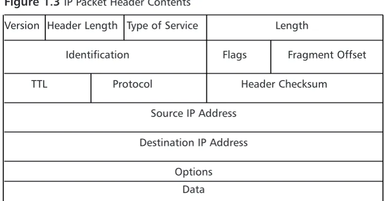
[image:42.501.60.456.328.534.2]As discussed in the previous sections, IP is essentially used to get data from one system to another.The anatomy of IP is very straightforward. In Figure 1.3 you can see what exactly makes up an IP packet header. An IP packet contains the very important application data that needs to be transported.This data is con-tained in the last portion of the packet.The IP portion of a packet is called the IP header. It contains all of the information that is useful for getting the data from system to system.The IP header includes the source and destination IP addresses.
Figure 1.3 IP Packet Header Contents
Version Header Length Type of Service Length
Identification Flags Fragment Offset
TTL Protocol Header Checksum
Source IP Address
Destination IP Address
Options
Data
envelope it tells the recipient where to send return mail to.The packet also receives the destination address of the web server being contacted.There are other parts that are set in the IP header, but are not germane to this discussion. After the packet is created, it is sent to the originating system’s routing table.The routing table is referenced and then the operating system determines which path to send this packet to. In routing, each system that receives the packet determines the next location or hop to send the packet to. So when sending information or requests across the Internet, there may be 15 hops or routers to go through before you get to the final system you are trying to connect to. Simply stated, a router is a system whose primary function is to route traffic from one location to another. As each router receives a packet it determines the next best location to send it to.
This, of course, is very simplified, as there are millions of routers on the Internet. Once the destination system receives the IP packet, it formulates a response.This is then sent back to the client system.The IP header contains the source address of the server that received the first packet and then the destination address of the initiating client machine.This is the fundamental basis of IP com-munications.
One of the confusing things about IP is that IP packets are not just used to transport data; the IP protocol suite does more than that. If you refer back to Table 1.1, you can see a field called protocol.This determines which IP protocol the packet is using. All of the available IP protocols are specified in RFC 1700. Table 1.1 is a short reference of the IP protocols we will be discussing in this book. For example, if the packet was UDP, it would be using IP protocol 17, and if the packet was IP Security (IPSec) ESP, it would be using IP protocol 50.
Table 1.1 IP Protocol Suite
Protocol Number Name Protocol
1 ICMP Internet Control Message Protocol
4 IP IP to IP Encapsulation
6 TCP Transmission Control Protocol
17 UDP User Datagram Protocol
50 ESP Encapsulating Security Payload
One of the most important protocols in the IP protocol suite is the Internet Control Messaging Protocol (ICMP). ICMP is used as a messaging protocol to give information to the source or destination machine that is engaging in IP communications.Table 1.2 lists all of the commonly used ICMP types and codes. To give an example of ICMP, let’s look at the common application ping. Ping is an application that is on pretty much any operating system, including ScreenOS. It is used to test if a host is responsive from a network perspective. When you ping a host, an IP packet is generated that has the source IP address of the requesting system and the destination IP address of the system you are trying to contact.This packet then has an ICMP type of eight and a code of zero.The des-tination system then would receive the packet and recognize that the IP packet is echo or echo request packet. It then creates an ICMP packet that is a type zero code zero.This is an echo reply packet, acknowledging the original request.
Devices use ICMP for other reasons as well. If a system had a route in its routing table that specified a host could be found at a location that did not exist, the router it points to would send an ICMP message to the initiating host.That router would send a type three code zero or code one message specifying that the network or host is not available. Now apply that to the Internet and all of those millions of routers out there.This makes the ICMP protocol very helpful for notifying users when there is a problem with getting IP packets from one location to another.
Table 1.2 ICMP Types and Codes
Type Name
0 Echo Reply
Codes Name
0 No Code
Table 1.2 ICMP Types and Codes
Type Name
3 Destination Unreachable
Codes Name
0 Network Unreachable
1 Host Unreachable
2 Protocol Unreachable
3 Port Unreachable
What Does an IP Address Look Like?
IP addresses are thirty-two bits in length.They consist of four eight-bit numbers. An example of an IP address is 1.2.3.4.This looks like a very simple format, but it has a great deal of meaning. Each of the four numbers can contain a value from 0 to 255. IP addresses are allocated in blocks or subnets. A subnet is a grouping of IP addresses based upon a subnet mask.There are three major types of IP address blocks, class A, B, and C. Each class is determined based upon the three leading bits for each number.The class A grouping of IP addresses all start with the binary digit 0.The class B grouping of IP addresses all start with 10. Finally, the class C grouping of IP addresses all start with 110. In Table 1.3 you can see all of the ranges of IP addresses based upon class.There are two other classes of IP addresses, classes D and E, which have special functions that are not covered in this book.
Table 1.3 IP Address Ranges by Class
Class Address Range
A 0.0.0.0 to 127.255.255.255
B 128.0.0.0 to 191.255.255.255
C 192.0.0.0 to 223.255.255.255
D 224.0.0.0 to 239.255.255.255
E 240.0.0.0 to 255.255.255.255
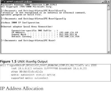
mand ipconfig. An example of this is shown in Figure 1.4 below.You can also do the same thing on a UNIX-based system by using the command ifconfig. An example of this is shown in Figure 1.5 below.
IP Address Allocation
[image:46.501.64.455.131.452.2]When creating a network, deciding on IP address allocation is very important. But with billions of options, how does one decide? The Internet Assigned Numbers Authority, or IANA, is responsible for allocating IP addresses.They determine which organizations get which IP address ranges.They are also responsible for conserving IP addresses and planning for future uses for IP addresses. Does this mean that you need to contact them to get IP addresses? Unless you are starting your own Internet Service Provider (ISP) the size of Qwest or SBC, you do not need to contact them.Your ISP will always assign any Internet or public IP addresses, and for private IP address networks you would use the IP addresses that are specified in RFC 1918. See Table 1.4 for a list of the Figure 1.4 Microsoft Windows ipconfig Output
private IP address ranges. A non-Internet routable IP is an IP address that is not routed on the Internet. If a packet was to leave your network with a source or destination IP address in one of these ranges, it would not get very far.
Table 1.4 RFC 1918 IP Address Ranges
Class Address Range
A 10.0.0.0 to 10.255.255.255 B 172.16.0.0 to 172.31.255.255 C 192.168.0.0 to 192.168.255.255
NAT and Private IP Addresses
Most companies need to access Internet resources while preserving Internet IP addresses.The solution is Network Address Translation, or NAT. NAT is used to hide your private IP address behind a public IP address.This allows private IP-addressed systems to access publicly IP-addressed systems. NAT also provides a layer of security by hiding the real IP addresses of your internal network. A gateway device such as a NetScreen firewall performs NAT for IP packets that pass through the device. Once the firewall receives an IP packet with the source IP address, it changes the private IP address into a public IP address. When the NetScreen firewall receives the return packet, it translates the new destination address to the private IP address.There are two types of NAT: NAT source, and NAT destination.
TCP Communications
The Transmission Control Protocol is used to control the creation and form of data transfer connections.TCP is one of two transport layer protocols that are used as part of the TCP/IP protocol suite.TCP is designed to provide many functions mostly based on reliability.TCP is used for applications that require reliability over speed. When talking about speed at this level, we are talking about calculations of milliseconds or less.TCP functions as a stateful protocol.This means that during the communications, the connection has specific states in which it functions.There is a clear beginning, middle, and end of a TCP connection.
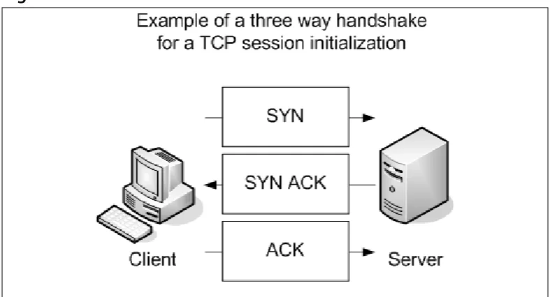
shown in Figure 1.6. Let’s continue to use our earlier example of using your web browser to access www.syngress.com. When your web browser attempts to make its connection to the web server, it attempts to open a connection to TCP port 80. A port is a specific communications channel specific to a particular applica-tion.TCP port 80 is the default port for HTTP.
The first packet that is sent to the web server is a SYN packet. A SYN packet is used to synchronize a connection between two hosts.This packet is also sent with a sequence number that is used to identify the packet inside of this connec-tion.This sequence number is to be used for the initiating systems packets. Next, the web server receives the packet acknowledges it.To do this, the server creates and sends a packet with the TCP flags SYN and ACK. A packet that has the ACK (or acknowledgment) flag set is sending a message to the other system that says, “I have received your packet”. A sequence number is also given to this packet that is independent of the sequence number that is associated with the initiating system’s sequence number.The system that initiated the connection now sends an ACK packet to acknowledge the connection.The ACK packet has a sequence number that is incremented, as it is the second packet that has been sent from this system.The TCP session has now been created and the requested data from the web server can begin to pass to the client.
The data that was requested is divided into packets by TCP.The client sends a TCP packet with the ACK flag for each part of the data. Again, each packet that is sent from the client has a sequence number that is incremented by one.The sequence number is used to identify all of the packets of a TCP exchange. If, for example, a client receives packets with sequence numbers 6, 7, 8, and 10, but never receives packet 9, the client will request that packet nine be resent from the server. On the client, all of the packets would be reordered before passing the data back to the application. When the connection is completed, the server system would send a packet with the FIN flag.This indicates that the connection is finished.The client would then send an ACK packet back to the server
UDP Communications
The User Datagram Protocol is a connectionless protocol that is designed to stream data. When a UDP connection occurs, there is no beginning, middle, or end to the conversation. Data simply begins to flow between the two systems. UDP is a very simple protocol and is used when speed is an issue. UDP packet receipt is not verified. An example of a use of the UDP protocol is DNS queries. When you attempt to use your web browser to access www.syngress.com, it must first resolve the name to an IP address.This would require a DNS query.The query is sent over a single UDP packet.The DNS server would then respond by telling the originating system the IP address of the web server. Because the UDP response is faster than setting up a TCP session, UDP makes sense in these situa-tions. Another example of using UDP is Voice over IP (VoIP).The downfall, of course, is the lack of reliability, so you may have to employ other methods to guarantee delivery.
What is a Port?
[image:49.501.45.439.68.281.2]Each port contains a specific type of content or application. When you tune to that port, you can access those specific resources.Theoretically, you can put any application on any port, but by specifying specific ports for specific applications, you can always be assured of the type of content you will find on a specific port.
This is why a specification of well-known ports has been established.Table 1.5 gives a list of well-known TCP and UDP ports. Using our earlier television example, this is much like a channel lineup. If television programming could appear on any television channel, there would be a lot of confusion about which programming you were watching. When you use your television, the service provider gives you a channel lineup.This lineup is specified so that you know which channel is which. Most web servers serve data over port 80. Again, they can serve the data over any port, but it would be very hard to get the content if you did not know which port to use.
Table 1.5 Well-Known TCP and UDP Ports
Well-Known TCP Ports Well-Known UDP Ports
FTP 21 DNS 53
SSH 22 DHCP-Relay 67
Telnet 23 TFTP 69
SMTP 25 NTP 123
HTTP 80 IKE 500
IMAP 143 Syslog 514
HTTPS 443 H.323 1719
Data Link Layer Communication
The last part of networking we are going to discuss is the data link layer, or layer two.This layer is essentially the protocol that operates on the specific physical medium. Each of the following function differently on the data link layer: Ethernet, ATM, Frame Relay, HDLC, SDLC, PPP, and Serial Line Internet Protocol (SLIP) to name a few. In this section how Ethernet functions will be focused on. As of the time of this writing the main layer two protocol that is used by NetScreen firewalls is Ethernet.
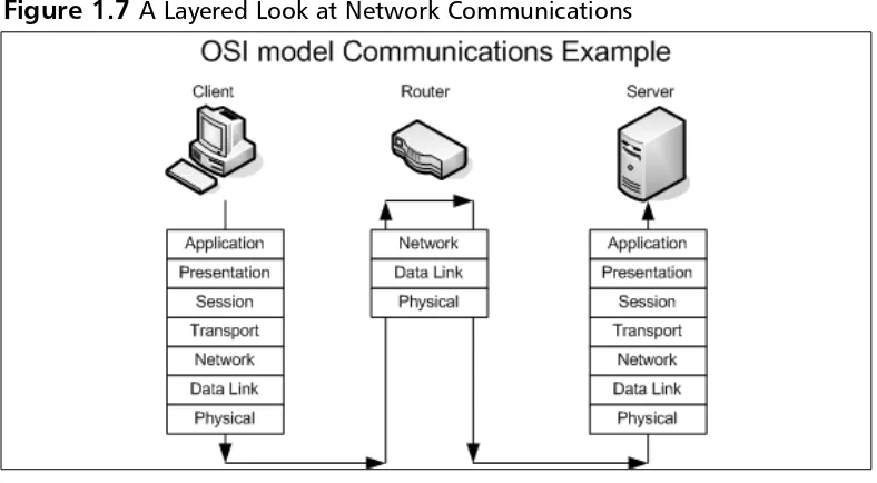
data link layer is used to communicate across the local medium. Figure 1.7 shows the breakdown of the use of layers and where they take place during system-to-system communication. When system-to-systems need to talk over Ethernet, they cannot use IP addresses, because Ethernet is at a lower level and it is used to move IP between layer three devices. So each device on an Ethernet segment uses a Media Access Control (MAC) address. When a station needs to have a conversa-tion, the source and destination systems use their MAC addresseses to identify each other. Each manufacturer is assigned a range to use when creating Ethernet adapters.Then each individual adapter is given a unique number to create the MAC address.
[image:51.501.46.440.216.433.2]a unicast message that specifies it has the IP address of 192.168.1.25 and also provides its MAC address.
Because almost everyone uses a computer today, a typical company can con-tain at least twenty computers or more.There are many ways to connect com-puters together. If you have just two systems, you can connect them with just a crossover Ethernet cable. A crossover cable is an Ethernet cable that allows two systems to directly connect to each other. If you have two to four computers, you could use a hub or bridge. If you have four or more computers, you will likely want to use a switch. A hub or bridge is a device that connects several sys-tems together. When two syssys-tems want to access the Ethernet media to transfer data, their communications take up the use of the media while they are talking. If a third system wants to talk over the network, it simply starts talking and the data frames will collide with those of the already ongoing communication. An
Ethernet segment where the media is shared between is called a collision domain. Switches, however, do not have this problem. When two systems begin a network conversation on a network with a switch, the packets are isolated and the switch prevents packets from colliding. If a system was to broadcast, however, the broad-cast would be sent to every system connected to the switch. When the switch sends the data between two hosts, it sends it such a way that other network con-versations are not interrupted.
Understanding Security Basics
The Need For Security
Enterprise security is the hottest technology trend today. Every aspect of a com-pany’s data infrastructure has the need for security. With ever–growing, ever-evolving networks in every organization, managing security has become harder. For many organizations, the operating budget for security is less than one percent of there total company budget. When it comes down to purchasing security products, firewalls are the core product used to secure the enterprise network. However, firewalls should by no means be the only method used to secure your network, but used effectively, they can mitigate the risks of network security breaches and data loss. With integrated technologies such as anti-virus, deep packet inspection, Uniform Resource Locator (URL) filtering, and Virtual Private Networks (VPNs), the firewall can provide a host of security applications all in one system. As the old saying goes, however, you should never put all of your eggs in one basket.
Introducing Common Security Standards
Security and network professionals use a number of currently accepted procedures and standards to conduct business and ensure that we are following the accepted practices for security and access. Although we have a responsibility as network and systems administrators to try to attain perfection in the availability and integrity of our data, we also have constraints placed on us in accomplishing those tasks.These constraints include budgets, physical plant capability, and training of users and tech-nicians to maintain the security and integrity of the data.These constraints do not relieve us of our responsibility of maintaining the data safely and securely.To that end, we currently employ some accepted standards for security that help us per-form our tasks to the best possible level. In this section, we remind you of the common security standards and briefly discuss them:
■ Authentication, authorization, and auditing (AAA) AAA use is required in security operations for creating and maintaining the method of authenticating users and processes, and validating their credentials prior to allowing access to resources. It is also the method we use to grant access or deny access to the resource. Auditing of activity is a cru-cial part of this function.
to protect our data from unauthorized view, corruption, or unautho-rized modification, and to provide constant availability. Over the past few years, the CIA processes have expanded to include a more compre-hensive guideline that also includes the process of defining risk and use of risk management tools to provide a more complete method of pro-tection.
■ Least privilege This concept is used by the security planners and teams to define the levels of access to resources and the network that should be allowed. From a security standpoint, it is always preferable to be too restrictive with the capability to relax the access levels than to be too loose and have a breach occur.
Remember, too, that the security process involves a three-tiered model for security protection:
■ Computer security, including the use of risk assessment, the expanded CIA goals, and enterprise planning that extends throughout the entire enterprise, rather than to just a portion of it.
■ Physical security, in which we must build and include physical access systems and coordinate them with our network access systems.
■ Trusted users,who become an important cog in maintaining the integrity of our security efforts.
Common Information Security Concepts
A generic dictionary definition of security (taken from the American Heritage Dictionary) is, “freedom from risk or danger; safety.”This definition is perhaps a little misleading when it comes to computer and networking security, because it implies a degree of protection that is inherently impossible to achieve in the modern connectivity-oriented computing environment.
secure your data, the more you impede accessibility. Any security plan is an attempt to strike the proper balance between the two.
Defining Information Security
Over the last couple of decades, many companies began to realize that their most valuable assets were not only their buildings or factories, but also the intellectual property and other information that flowed internally as well as outwardly to suppliers and customers. Company managers, used to dealing with risk in their business activities, started to think about what might happen if their key business information fell into the wrong hands, perhaps a competitor’s.
For a while, this risk was not too large, due to how and where that informa-tion was stored.Closed systemswas the operative phrase. Key business informa-tion, for the most part, was stored on servers accessed via terminals or terminal emulators and had few interconnections with other systems. Any interconnec-tions tended to be over private leased lines to a select few locainterconnec-tions, either internal to the company or to a trusted business partner.
However, over the last five to seven years, the Internet has changed how busi-nesses operate, and there has been a huge acceleration in the interconnectedness of organizations, systems, and networks. Entire corporate networks have access to the Internet, often at multiple points.This proliferation has created risks to sensi-tive information and business-critical systems where they had barely existed before.The importance of information security in the business environment has now been underscored, as has the need for skilled, dedicated practitioners of this specialty.
We have traditionally thought of security as consisting of people, sometimes with guns, watching over and guarding tangible assets such as a stack of money or a research lab. Maybe they sat at a desk and watched via closed-circuit cameras installed around the property.These people usually had minimal training and sometimes did not understand much about what they were guarding or why it was important. However, they did their jobs (and continue to do so) according to established processes, such as walking around the facility on a regular basis and looking for suspicious activity or people who do not appear to belong there.
Information security moves that model into the intangible realm.