Spontaneous vortices in optically shaped potential profiles in semiconductor microcavities
K. Guda,1M. Sich,1D. Sarkar,1P. M. Walker,1M. Durska,1R. A. Bradley,1D. M. Whittaker,1M. S. Skolnick,1 E. A. Cerda-M´endez,2P. V. Santos,2K. Biermann,2R. Hey,2and D. N. Krizhanovskii1
1Department of Physics and Astronomy, University of Sheffield, Sheffield S3 7RH, United Kingdom
2Paul-Drude-Institut f¨ur Festk¨orperelektronik, Berlin, Germany
(Received 13 November 2012; revised manuscript received 16 January 2013; published 21 February 2013) We investigate the spontaneous formation of quantized vortices in microcavity polariton high density phases. Condensates formed in the optical parametric oscillator excitation scheme reveal single vortices in the case of a ring-shaped optical potential or in the presence of natural photonic disorder. We further investigate the dynamics of vortex formation for resonantly injected polaritons and observe the formation of vortex-antivortex pairs, but no single vortices. The observed effects are explained by the interplay between breaking ofy→ −yreflection symmetry in the system and conservation of optical angular momentum.
DOI:10.1103/PhysRevB.87.081309 PACS number(s): 71.36.+c, 42.55.Sa, 78.55.Cr
I. INTRODUCTION
Coherent macroscopically occupied states (condensates) attract major interest since they exhibit a number of interesting phenomena, such as superfluidity, vortices, and solitons. As well as coherent condensates of liquid helium and dilute atomic gases, condensates of semiconductor microcavity polaritons constitute an appealing testbed, allowing easy optical manipu-lation and direct imaging of the condensate due to the photonic part of their hybrid light-matter wave function.1,2In contrast to the atomic Bose-Einstein condensate (BEC), the polariton system is a nonequilibrium system,3 where polariton flows from high-gain to loss-dominated areas play a crucial role in the formation of vortices.
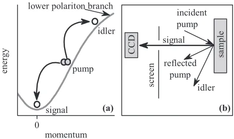
Vortices are topological defects which occur in many areas of science, including particle physics, cosmology, condensed matter, and optics. They tend to be stable states, as it requires a global, rather than local, perturbation to remove such a defect. Vortices occur in semiconductor lasers,4atomic Bose-Einstein condensates,5and liquid helium.6In equilibrium systems such as BEC of cold atoms or liquid helium the existence of a stable vortex is a manifestation of superfluidity. Spontaneous vortices have been reported recently in nonresonant incoherently pumped nonequilibrium polariton condensates in a CdTe microcavity,7,8where they arise from the interplay between po-lariton flows and the potential landscape, naturally present due to disorder or defects. In addition, the observation of vortex-antivortex pairs has been reported in incoherently pumped polariton condensates in a GaAs system which is pumped with a spatially varying excitation beam.9 Spontaneous polariton half vortices, where only one spin component of the condensate exhibits vortex formation, have also been observed.10 The investigation of spontaneous vortices in polariton systems has been extended to the system of a high density superfluid state, flowing against an obstacle at velocities close to the critical velocity.11–14In this case polaritons are directly injected by the resonant laser beam into the system rather than spontaneously forming due to polariton relaxation from higher energy states. Nonequilibrium polariton condensates arising from polariton-polariton parametric scattering for resonant exci-tation into the lower polariton branch, the so-called optical parametric oscillator (OPO; see Fig. 1, top panel), also attract significant interest.15,16 Importantly, the phase of the
signal is not imprinted by the pump but is a result of the spontaneous symmetry breaking, as in the case of incoherently pump condensates.17 However, OPO condensates are more complicated, consisting of three coupled signal, pump, and idler states. Krizhanovskiiet al.demonstrated the imprinting of vortices18 in the OPO system by using an external probe beam, which also allows polariton metastable flows19–21to be explored on a long time scale of 100 ps.
In this Rapid Communication we report the observation of spontaneous vortices in OPO condensates. First, we show that vortices arise spontaneously in an artificially created potential landscape: The excitation by a ring-shaped pump beam, carrying zero orbital angular momentum (OAM), creates an optically induced polariton potential. This results in the formation of a vortex with charge L=1, which forms due to breaking of they → −yreflection symmetry of the system (yis the direction perpendicular to the pumpkvector). Second, we investigate vortex formation in an artificial condensate created due to resonant polariton injection by a pulsed ring-shaped pump beam. In contrast to the OPO case, in this con-figuration vortex-antivortex pair creation is observed at about 10–20 ps after the initial pulse, thus conserving the initial total OAM of zero of the system at all times. Finally, we show that stable single vortices may arise spontaneously in a sample with a photonic disordered potential. As in the case of incoherently pumped condensates, this occurs due to polariton flow in the local potential landscape. Changing the excitation pump power alters the effective potential acting on the polaritons and can lead to the disappearance or appearance of vortices.
II. SAMPLES AND EXPERIMENTAL TECHNIQUES
FIG. 1. Schematic of the experiment.
potential disorder of 100–200μeV. The typical Rabi splitting in all samples is about 6 meV. Regions with near zero detuning between the exciton and cavity photonic mode atk=0 were investigated.
The samples were cooled to aboutT =4 K. Spatial phase information of the condensate is extracted by a Michelson interferometer with one of the mirrors being a retroreflector which rotates the image by 180◦.7In order to achieve a ringlike polariton condensate the excitation pump beam is focused into a 50μm spot onto a glass sheet with an opaque circular gold disk of 10 μm diameter. The image of the mask is further projected onto the sample in order to pump the OPO or directly inject polaritons atk=0.
III. SPONTANEOUS VORTICES IN OPO CONDENSATE USING RING-SHAPED EXCITATION
We first investigate sample 1 in the OPO configuration. Condensation is achieved by pumping the sample with a zero-orbital angular momentum (OAM) single-mode continuous-wave Ti:sapphire laser at an angle of 14◦close to the inflection point [see Fig.1(a)]. Figure2(a)shows an image of the signal polariton condensate in real space excited with a uniform pump beam. The condensate emission is nearly homogeneous across the sample, indicating very weak polaritonic potential disorder. The condensate spatial coherence was analyzed using a Michelson interferometer. The signal image shown in Fig.2(a) and its image inverted around a central point of symmetry were overlapped on the CCD camera to produce the interference pattern, shown in Fig.2(b). The region labeled A is overlapped with the one labeled B. The resultant interference fringes ex-tend over the whole condensate region of 30–40μm, indicating the buildup of long-range spatial coherence. We now pump the system using the ring-shaped pump beam as described above. Figure2(c)shows the signal condensate emission, which has a doughnut shape. Again, the condensate image in Fig.2(c)is overlapped with its inverted image in such a way that point B, where the polariton emission intensity now has a minimum, in-terferes with point A of maximum intensity. The resultant inter-ference pattern shown in Fig.2(d)exhibits clearly two forklike dislocations, indicating vortex formation with orbital angular momentum OAML=1. The interference pattern is symmet-ric with apparently two vortices, but this is an artefact caused by using the inverted image as phase reference. The position of the forklike dislocation in the interferogram coincides with the position of the local minima in the emission spot.
FIG. 2. (a) Spatial image of a uniform OPO condensate. (b) Interference pattern obtained by interfering the image with its inverted image and overlapping positions A and B. No fork, i.e., no vortex, is observed. (c) Image of a ring-shaped condensate, induced by a ring-shaped pump beam. The corresponding interference image (d) reveals a single spontaneous vortex inside the ring. (e) and (f) show the case where the mask was moved toward the edge of the beam and no vortex forms.
The physical origin of the spontaneous vortex formation can be understood in the following way: Polariton-polariton interactions are stronger in the high than in low density region, forming an optically induced potential trap due to density-induced polariton blueshifts. As a result, polaritons flow from high to low density regions, gaining kinetic energy and acquiring rotary motion, resulting in a vortex state. The radius of the optical potential trap is of the order of the condensate healing length ofξ ∼5μm.18 In this case the kinetic energy associated with the vortex carrying OAML=1 is similar to the potential energy associated with repulsive interactions in the high density region (∼0.1–0.2 meV), keeping the condensate energy constant across the excitation spot. This favors formation of a vortex with OAM ofL=1 in the center of the trap. We note that vortex formation requires an optical trap with well-defined boundaries. When the opaque mask is moved close to the edge of the excitation spot, no vortices are observed, as shown in Figs.2(e)and2(f).
It is an open question which mechanism selects the sign of the vortex OAM observed in the experiment. In a perfectly symmetric OPO system withy → −y reflection symmetry perpendicular to the pump wave vector (kp,0), states with OAM of bothL=1 andL= −1 are expected to be formed. However, such reflection symmetry can be broken easily by an irregular doughnut shape of the pump spot. As a result, formation of a vortex state with a particular sign of the OAM is preferred.
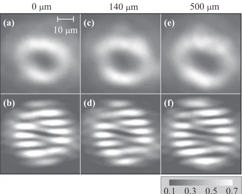
[image:2.608.320.552.71.248.2]FIG. 3. (a), (c), and (e) are the spatial images of a ring-shaped OPO condensate taken at different excitation spot positions across the sample. Positions in (c) and (e) are separated from that in (a) by 140 and 500μm, respectively. (b), (d), and (f) show the corresponding interference patterns obtained by interfering the images in (a), (c), and (e) with their corresponding inverted images. A vortex with OAM of
L=1 is always observed independently of the excitation position. out the role of the weak disorder potential in sample 1 in breaking the reflection symmetry, which otherwise, due to its randomness, would have lead to the observation of vortices of different charges at different positions across the sample.
Our observation of spontaneous vortices in a ring-shaped condensates contrasts with that of Manniet al., where they report a multilobe standing wave pattern in an incoherently pumped condensate excited with a ring-shaped beam.23 In contrast to the OPO case studied in our work, their observation indicates the breaking of cylindrical but not of reflection symmetry in the system, triggering condensation into a state which is a superposition of wave functions with both OAM of L=1 and L= −1. Nevertheless, we note that vortices only with OAML=1 are observed in incoherently pumped condensates in the presence of a disorder potential,7 which may in this case inhibit the reflection symmetry.
IV. SPONTANEOUS VORTICES IN OPO CONDENSATE IN STRONGLY DISORDERED SYSTEM
Turning now to the experiments on OPO condensation in the strongly disordered MOCVD grown sample 2, we observe stable spontaneous vortices in the signal state for a uniform Gaussian pump beam. Figure 4(a) shows the spatial image of the signal spot for a pump power three times above the condensation thresholdPth∼10 mW. The localized dark spot near the edge of the image, labeled A on the figure, is the position of the vortex core.
Figure 4(b) shows the interference pattern between the signal image of Fig.4(a)and its inverted image. Region A inter-feres with region B. The forklike dislocation in the interference pattern demonstrates the presence of a state with OAML=1. Such an observation of a spontaneous vortex in a disordered system is very similar to that in incoherently pumped
con-FIG. 4. Appearance of a spontaneous vortex at a structural defect in the OPO condensate. (a) shows the spatial image of the condensate, and (b) the interference pattern obtained by interfering the image with its inverted image and overlapping positions A and B. A single fork dislocation corresponds to a vortex with OAML=1.
densates in CdTe microcavities,7where the vortex formation depends on the local conditions. The difference is that in our system we have also an antivortex state formed in the OPO idler state at a wave vector of 2kp due to OAM conservation in the scattering process from the pump state with zero OAM. The polariton density and thus the total effective polariton potential profile vary as a function of excitation power, which may affect the vortex stability. Figures 5(a)–5(c) show the interference patterns for different excitation powers. Close to the threshold, at∼1.1Pth [Fig.5(a)], no vortex is found, and the spatial image of the emission is smooth (not shown) and exhibits no dip in the intensity. However, at powers of 2Pth and 3Pth [Figs. 5(b) and 5(c), respectively], vortices with OAML=1 are apparent in the interferograms. It can be clearly seen that the position of the vortex changes with increasing excitation power. The appearance of vortices only at higher powers shows that the formation of spontaneous vortices is affected by the local disorder potential as well as by an optically induced potential and increased polariton flow at higher pump density.
V. DYNAMICS OF SPONTANEOUS VORTICES IN POLARITON SYSTEM RESONANTLY DRIVEN ATk=0
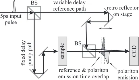
In the following experiment we investigate the dynamics of vortex formation due to polariton flows in an optically induced potential. We investigated MBE grown sample 3 which contains InGaAs quantum wells emitting at 850 nm, and thus allows the polariton evolution to be studied in transmission geometry. The experimental arrangements shown in Fig.6are very similar to that in Ref.12. In contrast to the OPO described
× × × ×
[image:3.608.51.295.68.264.2] [image:3.608.326.544.70.163.2] [image:3.608.314.559.605.713.2]sampl
e
CCD
5ps input pulse
fixed delay pump path
variable delay
reference path retro reflector on stage BS
BS
polariton emission reference & polariton
[image:4.608.53.295.72.212.2]emission time overlap
FIG. 6. The schematics of the transmission experiment.
above, where polaritons scatter from the pump state into the
k=0 signal state, a pump pulse resonant with the lower polariton branch atk=0 creates a polariton population in the system, which then is monitored as a function of time by inter-fering the emission of the transmitted laser pulse with a refer-ence pulse. Changing the delay time between the pump and the reference pulse allows us to monitor the temporal evolution of the spatial phase of the polariton field inside the microcavity.
Figure 7(a) shows the spatial image of the transmitted beam. It is seen that the image is nonuniform due to spatial disorder present in the system, although the disorder is less pronounced than in sample 2. As in the experiment described above, we introduce an opaque mask into the pump beam in order to create a dark region (encircled) and an optical trap in the polariton field. Figures7(b)–7(d)show the interference pattern arising from overlapping the transmitted pump and a reference beam having a constant phase. At time t=0 no forklike dislocations and hence no vortices are observed in the system. However, the phase becomes disturbed at about 6 ps and then clearly a vortex (V)-antivortex (AV) pair is observed at aboutt =16 ps [Fig.7(d)]. We note that such an observation of a V-AV pair is real and is not an artefact as in Fig.2, where
FIG. 7. (Color online) Images of the transmitted beam with and without a 10μm mask in the pump beam path are shown in (a) and (e), respectively. A potential trap due to a lower polariton density is formed when the mask is present in the encircled area. (b)–(d) are interference images obtained with a reference pulse att=0, 6, and 16 ps and show the dynamics of the formation of a vortex-antivortex pair. (f)–(h) Without the potential trap, no vortex pair is formed.
the inverted image itself is used as the reference beam instead of a reference beam of constant phase. If we remove the opaque mask out of the pump beam then no vortices form in the system at any time [see Figs.7(f)–7(h)].
As in the case of the OPO condensate, spontaneous vortices form due to polariton flows toward the region with smaller potential energy. The time scale of vortex formation is probably given by the time it takes for polaritons to propagate from high density regions toward the center of the trap, which occurs at a speed of about∼1μm ps−1.
We investigated several positions on the sample and always observe V-AV pairs, but never a single vortex. Such an observation is dictated by the OAM conservation law: If the closed system was initially prepared in a state with OAM of
L=0, then a vortex withL=1 arising from polariton flow should be accompanied by an antivortex12–14withL= −1 in order to preserve the total OAM ofL=0. In the case of the OPO condensate, where the signal is observed to have a single vortex, the OAM is still conserved, leading to an antivortex state in the idler state, which is not recorded. By contrast, in the transmission experiments all polaritons are prepared and detected atkvectors close to zero, leading to the observation of the V-AV pair.
Concerning the OPO case, we note that vortex and antivortex formation in the OPO signal is not excluded in spite of the presence of the idler, although not observed in experiment. For example, a moving A-AV pair was observed in a spatially extended OPO signal perturbed with a probe pulse beam carrying an OAM ofL=1.21 We speculate that if a V-AV pair indeed occurs in the signal state of the OPO pumped by a cw beam, one of the vortices may escape out of the excitation spot region and the other vortex is trapped by the optical potential.
While the path of the vortex movement is defined by the potential probably given by the shape of the optical beam, it is an open question why one vortex moves in one direction and the antivortex in another. Also the recombination of vortices is not observed with time. Again, this happens probably due to the lack of reflection symmetry with respect to the axis going through the cores of the V-AV pair due to the irregular shape of the optical potential.
VI. CONCLUSION
To conclude, we showed the spontaneous formation of quantized vortices in OPO polariton condensates: First, spontaneous single vortices can be observed in an optically induced ring-shaped potential trap and, second, they can also be observed at structural defects. In the case of a polariton population injected resonantly atk=0 by a pump pulse in transmission geometry a pair of vortices with OAM of opposite sign can develop, which preserves the initial injected OAM of
L=0. This excludes the observation of single vortices for such a configuration.
ACKNOWLEDGMENT
[image:4.608.52.294.524.667.2]1Exciton Polaritons in Microcavities: New Frontiers, edited by D. Sanvitto and V. Timofeev, Springer Series in Solid-State Sciences (Springer, Berlin, 2012).
2A. Kavokin, J. Baumberg, G. Malpuech, and F. Laussy,
Microcav-ities(Oxford University Press, Oxford, UK, 2007).
3M. Wouters and I. Carusotto, Phys. Rev. Lett. 99, 140402 (2007).
4J. Scheuer and M. Orenstein,Science285, 230 (1999).
5M. R. Matthews, B. P. Anderson, P. C. Haljan, D. S. Hall, C. E. Wieman, and E. A. Cornell, Phys. Rev. Lett. 83, 2498 (1999).
6W. F. Vinen,Proc. R. Soc. London, Ser. A260, 218 (1961). 7K. G. Lagoudakis, M. Wouters, M. Richard, A. Baas, I. Carusotto,
R. Andre, L. S. Dang, and B. Deveaud-Pledran,Nat. Phys.4, 706 (2008).
8K. G. Lagoudakis, F. Manni, B. Pietka, M. Wouters, T. C. H. Liew, V. Savona, A. V. Kavokin, R. Andre, and B. Deveaud-Pledran,Phys. Rev. Lett.106, 115301 (2011).
9G. Roumpos, M. Fraser, A. Loffler, S. Hofling, A. Forchel, and Y. Yamamoto,Nat. Phys.7, 129 (2011).
10K. G. Lagoudakis, T. Ostatnicky, A. V. Kavokin, Y. G. Rubo, R. Andre, and B. Deveaud-Pledran,Science326, 974 (2009). 11S. Pigeon, I. Carusotto, and C. Ciuti,Phys. Rev. B 83, 144513
(2011).
12G. Nardin, G. Grosso, Y. Leger, B. Petka, F. Morier-Genoud, and B. Deveaud-Pledran,Nat. Phys.7, 635 (2011).
13D. Sanvitto, S. Pigeon, A. Amo, D. Ballarini, M. D. Giorgi, I. Carusotto, R. Hivet, F. Pisanello, V. Sala, P. S. S. Guimaraes et al.,Nat. Photon.5, 610 (2011).
14A. Amo, S. Pigeon, D. Sanvitto, V. G. Sala, R. Hivet, I. Carusotto, F. Pisanello, G. Lemnager, R. Houdre, E. Giacobinoet al.,Science 332, 1167 (2011).
15R. M. Stevenson, V. N. Astratov, M. S. Skolnick, D. M. Whittaker, M. Emam-Ismail, A. I. Tartakovskii, P. G. Savvidis, J. J. Baumberg, and J. S. Roberts,Phys. Rev. Lett.85, 3680 (2000).
16A. I. Tartakovskii, D. N. Krizhanovskii, and V. D. Kulakovskii, Phys. Rev. B62, R13298 (2000).
17M. Wouters and I. Carusotto,Phys. Rev. A76, 043807 (2007). 18D. N. Krizhanovskii, D. M. Whittaker, R. A. Bradley, K. Guda,
D. Sarkar, D. Sanvitto, L. Vina, E. Cerda, P. Santos, K. Biermann et al.,Phys. Rev. Lett.104, 126402 (2010).
19D. Sanvitto, F. M. Marchetti, M. H. Szymanska, G. Tosi, M. Baudisch, F. P. Laussy, D. N. Krizhanovskii, M. S. Skolnick, L. Marrucci, A. Lemaitreet al.,Nat. Phys.6, 527 (2010). 20F. M. Marchetti, M. H. Szymanska, C. Tejedor, and D. M. Whittaker,
Phys. Rev. Lett.105, 063902 (2010).
21G. Tosi, F. M. Marchetti, D. Sanvitto, C. Antn, M. H. Szymanska, A. Berceanu, C. Tejedor, L. Marrucci, A. Lemaitre, J. Blochet al., Phys. Rev. Lett.107, 036401 (2011).
22D. M. Whittaker,Superlattices Microstruct.41, 297 (2007). 23F. Manni, K. G. Lagoudakis, T. C. H. Liew, R. Andre, and