Joint Optimization of Iterative Source and Channel Decoding
Using Over-Complete Source-Mapping
A. Q. Pham, L. L. Yang, and L. Hanzo
School of ECS, University of Southampton, SO17 1BJ, UK Tel: +44-23-8059 3125, Fax: +44-23-8059 4508
Email:{apq03r,lly,lh}@ecs.soton.ac.uk, http://www-mobile.ecs.soton.ac.uk
Abstract— The intentionally imposed or inherent unintentional residual redundancy found in source encoded bitstreams can be exploited for supporting joint SoftBit-Source Decoding and Channel Decoding, which has the potential of improving both the error correcting capability as well as the subjective audio or video quality of communication systems. As a potent error concealment technique, the softbit-based source decoding, proposed by Adrat, Vary and Spittka exploits the residual redundancy or correlation inherent in the source codec parameters for mitigating the effects of transmission errors. However, when using efficient source encoders, limited source redundancy is left in the source-encoded bitstream. In this scenario the SoftBit-Source Decoder (SBSD) may have a limited extrinsic information contribution, which results in no system performance improvements beyond two decoding iterations.
In our novel approach, we partition the total available bit-rate budget between the source and channel codecs in order to improve the attainable error correcting capability and hence to maximize the overall system’s performance. More explicitly, the inherent redundancy in the encoded bitstream is intentionally increased with the aid of over-complete mapping, andEXtrinsic Information Transfer(EXIT) charts are used for designing a suitable mapping of the source-coded bits to the modulated symbols, leading to an approximately2dBsignal-to-noise gain.
Keywords: generalized low-density parity-check codes, iterative source-channel decoding, extrinsic information transfer charts, over-complete mapping.
I. INTRODUCTION
According to Shannon’s source and channel coding separation theorem [1] these operations may be carried out separately, following separate optimization of each component. However, in the context of limited-complexity, limited-delay, lossy source codecs, which exploit the psycho-visual and psycho-acoustic properties of human percep-tion, Shannon’s lessons have limited applicability, as detailed in the preface of [2]. This is particularly so, when the real-time, interactive video system experiences bursty errors inflicted by dispersive fading channels, rather than independent random errors. For these scenarios source-decoding techniques have also been designed to exploit the residual redundancy inherent in the source-encoded bitstream for the sake of achieving additional error protection [3], [4]. Based on these source-decoding techniques, several iterative source-channel decoding approaches have been investigated, leading to a variety of guidelines. For example, in [3] and [4] the source decoder exploited the inherent residual redundancy in the encoded bitstream for the sake of providing an increased error protection. By contrast in [5] Buttigieg deliberately increased the inherent residual redundancy in the encoded bitstream, creating a class of Variable-Length Error-Correcting (VLEC) codes, which combines the benefits of variable-length coding with improved distance properties.
More recently, Adrat and Vary [6] have introduced an itera-tive source-channel decoding scheme, which improves the Soft-Bit Source Decoder’s (SBSD) performance using a powerful index assignment. The remarkable Iterative Source and Channel Decoding (ISCD) scheme of [3] used EXIT charts for demonstrating that the
The financial support of the EPSRC, Swindon UK and the EU under the auspices of the PHOENIX as well as NEWCOM and Phoenix projects is gratefully acknowledged.
performance of the ISCD scheme employing the SBSD technique of [7] was highly dependent on the amount of inherent redundancy in both the source and channel codes. It was also demonstrated that the redundancy of the source-encoded bitstream plays a role, which is as important as the intentionally imposed redundancy of the channel code. Furthermore, in [3] the authors demonstrated that a necessary, but insufficient condition of ensuring successful ISCD is that the minimum residual redundancy quantified in terms of the auto-correlation of source codec parameters should beρmin= 0.77, which corresponds to a potential data rate reduction by∆N= 0.659
bit/symbol atN = 3bits/symbol. It is worth noting that in state-of-the-art video encoders, such as the MPEG4, JPEG2000 [8] and Dirac [9] schemes, there is little residual redundancy left in the source-encoded bitstream. Hence it is difficult to achieve further performance improvements with the aid of ISCD. The question arises then, whether there is any merit in intentionally imposing redundancy on the source-coded bitstream for the sake of constructing an attractive ISCD scheme. A further dilemma is, how to partition the limited total bit-rate budget between the source and the channel encoders, so that the channel-induced impairment of the recovered image is minimized.
In this paper, we embark on analysing the convergence behaviour of an ISCD scheme and propose a novel ISCD scheme employing a specific bit-to-symbol mapping scheme. The proposed scheme benefits both from the residual redundancy inherent in the source encoded bitstream and as well as from the intentional redundancy imposed by the specific mapping to be introduced in Section III. Our results will demonstrate that imposing redundancy on the source-coded bitstream has the potential of outperforming even the powerful benchmarker of [7] at the same overall transmission rate.
This rest of the paper is organized as follows. In Section II a brief review of ISCD is presented and the dependence of its performance on the potential redundancy of the source data is investigated using EXIT charts. In Section III we demonstrate, how this scheme exploits the intentionally introduced source redundancy, accompanied by our design guidelines. The proposed ISCD scheme’s performance is characterized in Section IV. Finally, our conclusions are provided in Section V.
II. ITERATIVESOURCE-CHANNELDECODING
A. System Overview
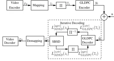
The block diagram of the ISCD scheme considered is shown in Fig. 1. At the transmitter, the Dirac wavelet video codec described in [9] is employed for compressing the video frames. The output binary sequence xi, i = 1,2, ..., P is then interleaved using the bit-interleaver Π of Fig. 3 and subsequently the interleaver’s
Encoder Video
Video
Decoder SBSD DecoderGLDPC
Iterative Decoding
n Encoder
GLDPC
Π−1 L[SBSDapri] (xk) L
[extr] GLDP C(xk)
ˆ
yk xk
Π
L[SBSDextr](xk) L [apri] GLDP C(xk)
Π xk yk
xk
Fig. 1. Iterative source and channel decoding model
0 0.1 0.2 0.3 0.4 0.5 0.6 0.7 0.8 0.9 1
0 0.1 0.2 0.3 0.4 0.5 0.6 0.7 0.8 0.9 1
IEI IAO
IAI IEO
SBSD without over-complete mapping
[image:2.612.81.272.40.150.2] [image:2.612.313.567.204.336.2]SBSD with over-complete mapping rate 3/4
Fig. 2. EXIT characteristics of SBSD with and without the aid of over-complete mapping. The distribution of the source-encoded bitstream is presented in Table I, M=3bits/symbol.
decoder. This reliability information can be evaluated either in terms of bit probabilities or as their log-likelihood ratios (LLRs). The
TABLE I
RESIDUAL REDUNDANCY IN THE WAVELET VIDEO-ENCODED BITSTREAM
MODELLED BY A ZEROTH-ORDERMARKOV CHAIN.
Symbol Probability Symbol Probability
0 0.2097020 4 0.1268470
1 0.0960067 5 0.0903356
2 0.0854893 6 0.0857518
3 0.1193480 7 0.1865200
conventional SBSD scheme determines the extrinsic information from the natural residual redundancy, which inherently remains in the bit patterns xk after source encoding, which manifests itself in terms of the non-uniform probability of occurence of the resultant bit patterns. In an attempt to simplify the receiver, we characterize this redundancy with the aid of the non-uniform M-ary symbol probability distribution P(uk), uk = (uk(1), ..., uk(M)). More explicitly, the source bit statistics were evaluated by dividing the wavelet video encoded bitstream into a 3 bits/symbol sequence
(u1(1), u1(2), u1(3), u2(1), ..., uκ(3)) = (x1, x2, ..., xP). In our simulations, the wavelet video-encoded bitstreams of the 150-frame
MissAmericavideo sequence, the 300-frameAkiyosequence and the 300-frame mother&daughter video sequence were used as training sequences. The relative frequency modelling the probability distribu-tion of the wavelet video-encoded bitstream is shown in Table I. The details of the algorithm used for computing the extrinsic LLR values of the 0-order Markov model can be found in [7]. We will briefly review this model next. Firstly, the channel’s ouput information generated for theτ-th M-bit symbol is given by the product of the single-bit probabilities:
p(ˆuτ|uτ) = M
Y
λ=1
p(ˆuτ(λ)|uτ(λ)), (1)
where uˆτ = (ˆuτ(1), ...,uˆτ(M)) is the reliability information of the τ-th M-ary symbol, while uτ = (uτ(1), ..., uτ(M)) is the corresponding transmitted symbol. The extrinsic channel-ouput in-formationp(ˆu[τextr]|u[
extr]
τ )generated for each desired bituτ(λ) is obtained as
p(ˆu[extr]
τ |u
[extr]
τ ) = M
Y
i=1 i6=λ
p(ˆuτ(i)|uτ(i)). (2)
Finally, the extrinsic value of each bit expressed in terms of the corresponding LLR can be obtained by combining the channel’s output information and oura prioriknowledge of the corresponding τ-th symbol:
LLR(uτ(λ)) =log
X
u[extr]τ
p(u[extr]
τ |uτ(λ) = +1)).p(ˆuτ[extr]|u[τextr])
X
u[extr]τ
p(u[τextr]|uτ(λ) =−1)).p(ˆu[τextr]|u[ extr]
τ )
=log
X
u[extr]τ
p(u[τextr]|uτ(λ) = +1)) M
Y
i=1 i6=λ
p(ˆuτ(i)|uτ(i))
X
u[extr]τ
p(u[τextr]|uτ(λ) =−1)) M
Y
i=1 i6=λ
p(ˆuτ(i)|uτ(i))
. (3)
B. EXIT characteristics of softbit source decoding
n Encoder
GLDPC Encoder
Video
Mapping
Decoder GLDPC SBSD
Demapping Video
Decoder
Iterative Decoding
Π
xk zi zi yi
Π
L[SDSDextr](zi) L
[apri]
GLDP C(zi)
Π−1
L[SDSDapri](zi) L
[extr]
GLDP C(zi)
ˆ
yi
ˆ
zi
xk
[image:2.612.336.532.366.471.2]Fig. 3. The improved iterative source and channel coding scheme
Fig. 2 depicts the EXIT characteristics of the SBSD for both uncorrelated uniform as well as for correlated and hence non-uniform distribution of the source-encoded bitstream shown in Table I. In order to analyse the dependence of the SBSD’s performance on the potential redundancy inherent in the source encoded data, the so-called over-complete Mapping 11of rate 3/4 detailed in Table II, was employed. This unsophisticated mapping scheme simply concatenates a logical 0 or 1 to the source-encoded symbol for the sake of
illustration. A more sophisticated mapping will be designed in Section III.
The block diagram of the resultant improved ISCD scheme is shown in Fig. 3. The simulation results of Fig. 1 and particular those of Fig. 6 reveal that the performance of SBSD strongly depends on the presence or absence of potential redundancy, which manifests itself in terms of the more uniform and hence uncorrelated or less uniform distribution of the source-encoded data. The entropy of the source denoted as Lextr
SBSD = H(X) may not reach 1bit, even if thea priori informationat the input of the SBSD is error-free, i.e., LapriSBSD '1bit. Hence, it is impossible to perfectly reconstruct the
1An over-complete mapping creates a source symbol setY from the set
[image:2.612.79.265.434.493.2]data bit xk of Fig. 3 by exploiting the extrinsic information at the output of the SBSD. Observe furthermore in Fig. 2 that the mutual information at the output of the SBSD increases approximately linearly with the mutual information IA at its input. In the next section we will investigate a more sophisticated EXIT-optimized over-complete mapping family.
TABLE II
OVER-COMPLETE SOURCE SYMBOL MAPPING OF RATE3/4USED IN THE
SIMULATIONS.
Symbol Mapping 1 Mapping 2
000 1000 0000
001 1001 1001
010 1010 1010
011 1011 0011
100 0100 1100
101 0101 0101
110 0110 0110
111 0111 1111
III. ITERATIVESOURCE-CHANNELDECODING USING
OVERCOMPLETESOURCEMAPPING
The aim of ISCD schemes is to extract as much extrinsic informa-tion Lextr
SBSD, LextrCD from both constituent decoders as possible for the sake of assisting each other. This implies that the intersection of the component decoders’ EXIT curves must be avoided all together for the sake of maintaining an open EXIT tunnel or should be located at the highest possible(Lextr
SBSD,L extr
CD)point2 in the EXIT chart. As mentioned above, in state-of-the-art video encoders there is little residual redundancy in the source-encoded bitstream and thus the achievable performance benefits of ISCD schemes are limited. In order to improve the attainable ISCD gains, we propose to find high performance over-complete mapping schemes which artificially introduce redundancy into the source-encoded bitstreams. A specific manifestation of the artificial redundancy introduced by the proposed over-complete mapping is that certain bit patterns do not occur at all after mapping. For example, Mapping 1 of Table II introduces the bit patterns{0000, 0001, 0010, 0011, 1100, 1101, 1110, 1111}with a probability of zero. In other words, only eight out of the 16 possible symbols are actively used.
However, as briefly exemplified in Section II-B, the artificially introduced redundancy imposed by over-complete mapping cannot ensure that the EXIT curve of the SBSD reaches the point(1,1)at
the upper-right corner of the EXIT chart, which implies convergence to an infinitesimally low BER. In order to create over-complete mapping schemes for succesful SBSD, we will formulateLemma1. Furthermore,Algorithm1 will outline how to construct near-capacity ISCD schemes, and as an additional result, the cardinality of EXIT-optimized mapping sets is also investigated.
Lemma 1: The EXIT curve of SBSD may reach the point
(ILapri
SBSD, I Lextr
SBSD) = (1,1) in the context of the ISCD scheme depicted in Fig. 3, if the source-encoded bits constituting the symbol set X mapped to the extended set f(X) using an over-complete mapping off(X) ={f(x)|x∈X}, has a Hamming distance3 of at leastdH= 2.
2The particular ISCD’s EXIT curves is considered to provide the ”highest
possible” performance if the sum of squares of the mutual information, i.e.
(ILextr
SBSD)2+ (IL
extr
CD )2is maximized.
3The Hamming distance between two binary codewords of equal length is
the number of positions for which the corresponding bits are different. The Hamming distance of the over-complete mapping f(X) is defined as the minimum Hamming distance between all possible codeword pairs
(f(x), f(y)),f(x), f(y)∈f(X).
Proof: Let uˆτ = (ˆuτ(1), ...,uˆτ(M)) be thea priori information sequence for the τ-th source symbol at the input of the SBSD and u0τ = (u0τ(1), ..., u0τ(M))be the corresponding transmitted bit sequence. BecauseILapri
SBSD= 1, we have
p(ˆu(τλ)|uτ(λ)) =
1 ifuτ(λ) =u0τ(λ)
0 otherwise, (4)
as well as
p(ˆu[τextr]|u[ extr]
τ ) = M
Y
i=1 i6=λ
p(ˆuτ(i)|uτ(i))
=
1 ifu[τextr]=u0[τextr]
0 otherwise. (5)
Combining (5) with (3) yields
LLR(uτ(λ)) =logp(u
0[extr]
τ |uτ(λ) = +1) p(u0[τextr]|uτ(λ) =−1)
. (6)
The lemma is proven if we can show thatLLR(uτ(λ))tends to+∞, asuˆτ(λ)→+∞, andLLR(uτ(λ))tends to−∞, asuˆτ(λ)→ −∞. Firstly, we consider the case whenLLR(uτ(λ))approaches +∞. SinceILapri
SBSD= 1, we haveI(ˆuτ, uτ0) = 1, which implies thatu0τ(λ) tends to the probability of unity, corresponding to a high confidence concerning its logical value, regardless whether it is a logicaloneor zero, if we haveuˆτ(λ)→+∞. Equation (3) therefore becomes
LLR(uτ(λ)) =log p(u
0[extr]
τ |uτ(λ) =u0τ(λ)) p(u0[τextr]|uτ(λ) =¬u0τ(λ))
=log p(u
0
τ) p(u0[extr]
τ |uτ(λ) =¬u0τ(λ))
, (7)
where ¬ represents a logical ”not” operator. Since the mapping
defined inLemma 1has a Hamming distance of at leastdH= 2, for a certain value ofu[τextr], there is only oneuτ(λ)value, which results in p(u[τextr]|uτ(λ)) 6= 0. Therefore the denominator of Equation 7 must be 0, and the right-hand side of Equation 7 tends to +∞ corresponding to a near-unity probability of p(u0τ) ≈ 1. A similar argument is valid, whenLLR(uτ(λ))tends to−∞, which completes the proof ofLemma 1.
Definition 1: The over-complete mapping f(X) is termed here
as an EXIT-optimized mapping, if the mapped symbols obeying f(X) ={f(x)|x∈ X} exhibit a minimum Hamming distance of dH= 2.
1) An Algorithm for Selecting EXIT-Optimized
Over-Complete Mapping Sets Let XM = {x =
(x0, ..., xM−1)|xi ∈ 0,1} be a set of binary symbols at
the ouput of the source encoder andI(x) =
M−1 X
i=0
xi∗2M−1−i
be the index of symbolx. Therefore the number of symbols inXM is2M. For a binary value ofu, letu=¬u, where¬ is again the logical”not”operator. Let us now define the set XM
A as follows:
XM
A ={(u(x0, ..., xM−1), x0, ..., xM−1)|xi∈0,1} (8) ={(u, x)|x∈XM}.
The sequence expressed as a function of the symbol indices
(x0, ..., xM−1), can be calculated using the following algo-rithm:
Algorithm 1: the prefix-bit selection algorithm
Input:M,Start bit;
Output:A binary sequenceu={u0, ..., u2M−1};
{
Step 3:SetM id=Stop−Start+ 1 2
u(M id) =¬u(Start)
where¬is a logical”not”operator. Step 4:if(Start=Stop)then gotoStep 7; Step 5:RepeatStep 2for the set
[Start, M id−1, u(Start)]; Step 6:RepeatStep 2for the set
[M id, Stop, u(M id)];
}
Step 7:Stop.
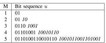
As an example, Table III shows the results of applying Algo-rithm 1 toustart = 0 for variousM values. To be specific, Mapping 2 of Table II which corresponds to M = 3 was obtained by appending the first binary symbol of the sequence ”01101001” at the begining of the first entry, the second at the begining of the second entry, etc. For the sake of illustrating the dependence of the results of Algorithm 1 on the distance
(Stop−Start)as well as on the value ofustart, the resultant binary sequences of Table III are partitioned into two equal length subsequences. Observe that the second subsequence uM id printed initalic font can be obtained by complementing the first subsequence uStart printed in normal font. Further-more, the sequencesustartandustart+kcalculated by applying Algorithm 1 to the set[Start, Stop, u(Start)]and to[Start+
k, Stop+k, u(Start)]are identical. In other words, the result of Algorithm 1 only depends on the values of(Stop−Start)
andu(Start).
TABLE III
PREFIX BIT SEQUENCEuAS A FUNCTION OFM.
M Bit sequenceu 1 01
2 0110
3 01101001
4 0110100110010110
5 01101001100101101001011001101001
Lemma 2: The set XM
A constructed above has a minimum Hamming distance4 ofd
H= 2. Proof: Assume thatXM
A has a Hamming distance ofdH= 1. This implies that there exists an index pairi, j∈I(XM), i= M−1
X
k=0
xi,k∗2M−1−k, j = M−1
X
k=0
xj,k∗2M−1−k, i 6= j for
which dh[(u(i), xi,1, ..., xi,M),(u(j), xj,1, ..., xj,M)] = 1. If we have i = j, then u(i) = u(j), and hence dh[(u(i), xi,1, ..., xi,M),(u(j), xj,1, ..., xj,M)] =
0. Therefore we have i 6= j, which means that dh[(xi,1, ..., xi,M),(xj,1, ..., xj,M)] >
1. Combining this with the assumption of
dh[(u(i), xi,1, ..., xi,M),(u(j), xj,1, ..., xj,M)] = 1, we have
u(i) =u(j). (9)
Thus dh[(xi,1, ..., xi,M),(xj,1, ..., xj,M)] = 1, which means that there exists a valuek∈ {0, ..., M−1}for which we have
i= (c0, ..., ck−1, ck, ck+1, ..., cM),
j= (c0, ..., ck−1, ck, ck+1, ..., cM). (10)
Observe that i and j belong to the same set
4The Hamming distance of the set X is defined as the minimum
Hamming distance between all symbol pairs of set X: dh(X) =
min(dh(ci, cj)|ci, cj∈X)
[Startk, Stopk, u(Startk)] after carrying out k − 1 partitioning steps in Algorithm 1. At the time instant k we have i ∈ [Startk, M idk, u(Startk)], and j∈[M idk, Stopk, u(M idk)]. As mentioned above, if we have the prefix sequences uStartk = (u(Startk,0), ...u(Startk,P))
and uM idk = (u(M idk,0), ...u(M idk,P)) generated by
Algorithm 1 from the set [Startk, M idk, u(Startk)] and from the set [M idk, Stopk, u(M idk)], respectively, then u(Startk,p) =u(M idk,p), ∀p∈ {0, ..., P}. It may be readily
seen from Equation 10 that the index ofiin uStartk and the
index ofjinuM idkare the same, namely
M−1 X
p=k+1
cp∗2M−1−p
and hence we haveu(i) =u(j). This contradicts to Equation 9, and hence we have no other option but to conclude that XM
A has a Hamming distance of at leastdH = 2. 2) Cardinality of EXIT-Optimized Mapping
Lemma 3: The cardinality5 of the EXIT-optimized mapping subset of the overcomplete mapping set f : XP → XM (P ≤M) is equal to2∗ 2
M−1!
(2M−1−2P)!. Proof: Observe that the setXM−1
A constructed by using Algo-rithm 1 foru(Start) = 0and exhibiting a Hamming distance of at leastdH = 2, has the cardinality ofkXAM−1k= 2
M−1. Hence, all the possible injective mappingsf :XP →XM−1
A are EXIT-optimized mappings. It is clear that the number of possible injective mappings f : XP → XM−1
A is equal to number of possible ways of obtaining an ordered subset of2P elements from a set of 2M−1 elements. In other words, the cardinality of the injective mapping set F = {f : XP → XM−1
A } is equal to the number of possible permutations P2P
2M−1 =
2M−1!
(2M−1−2P)!, where ”!” denotes the factorial operator. Note thatXM−1
B constructed by using Algorithm 1 for u(Start) = 1 also has a Hamming distance of at least dH= 2andXAM−1, XBM−1are non-overlapping sets obeying XM = XM−1
A ∪X M−1
B . Using the same argument allows us to quantify the number of the possible injective mappings ψ : XP → XM−1
B , which is also equal to the number of the possible permutations P2P
2M−1 =
2M−1!
(2M−1−2P)!, hence the number of over-complete mapping schemes f : XP → XM having a minimum Hamming distance of d
H = 2 is
2∗ 2 M−1!
(2M−1−2P)!, which concludes the proof of the lemma.
0 0.1 0.2 0.3 0.4 0.5 0.6 0.7 0.8 0.9 1
0 0.1 0.2 0.3 0.4 0.5 0.6 0.7 0.8 0.9 1
IEI
IAO
IAI IEO SBSD 1.5dB
2dB 2.5dB
3dB
GLDPC,RGLDPC=2/3 transfer function
SBSD transfer function 0
0.1 0.2 0.3 0.4 0.5 0.6 0.7 0.8 0.9 1
0 0.1 0.2 0.3 0.4 0.5 0.6 0.7 0.8 0.9 1
IEI
IAO
IAI IEO SBSD 1.5dB
2dB 2.5dB
3dB
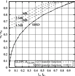
Fig. 4. EXIT characteristics of System 2 specified in Table IV and designed for transmission over the uncorrelated Rayleigh fading channel.
IV. EXPERIMENTALRESULTS
In this section, the attainable performance of the ISCD schemes of Figs. 1 and 3 is investigated for transmission over the uncorrelated
[image:4.612.84.265.389.462.2]0 0.1 0.2 0.3 0.4 0.5 0.6 0.7 0.8 0.9 1
0 0.1 0.2 0.3 0.4 0.5 0.6 0.7 0.8 0.9 1
IEI
IAO
IAI IEO SBSD 1.5dB
2dB 2.5dB
3dB
GLDPC,RGLDPC=2/3 transfer function
SBSD transfer function 0
0.1 0.2 0.3 0.4 0.5 0.6 0.7 0.8 0.9 1
0 0.1 0.2 0.3 0.4 0.5 0.6 0.7 0.8 0.9 1
IEI
IAO
IAI IEO SBSD 1.5dB
2dB 2.5dB
3dB
Fig. 5. EXIT characteristics of System 3 specified in Table IV and designed for transmission over the uncorrelated Rayleigh fading channel.
Rayleigh fading channel. The various system parameters are sum-marized in Table IV. The convergence behaviour of these systems
TABLE IV
THE SIMULATION PARAMETERS
Parameters System 1 System 2 System 3
Overall code-rate 0.5 0.5 0.5
GLDPC code-rate 1/2 4/5 4/5
Mapping rate 1 3/4 3/4
(Mapping 1) (Mapping 2)
[image:5.612.104.227.52.176.2]is characterized in Figs. 4 and 5. Observe by comparing Figs. 4 and 5 that both the amount of redundancy imposed by the complete mapping as well as the Hamming distance of the over-complete mapping play an important role. More specifically, the intersection of the EXIT-curves of System 2 using Mapping 1 of Table II is significantly closer to the(1,1)point of the EXIT-chart and consequently to the Eb/N0 value of infinitesimally low BER
than that of System 1. Furthermore, observe in Fig. 5 that at the same amount of redundancy, i.e. mapping rate, the EXIT-curve of System 3 indeed reaches the top-right corner of the EXIT chart, whereas that of System 2 fails to do so as evidenced by Fig. 4. Hence, although not shown here owing to the lack of space the iterative decoding gain of System 1 is limited to two iterations, while that of System 2 and System 3 improves further upon iterating four times.
The associated BER performances are shown in Fig. 6 for an overall code-rate of 0.5. More specifically, System 3 outperformed System 2 by about 1.75dB, and it has an approximately2dB gain also in comparison to System 1 for I= 4 iterations.
V. CONCLUSIONS
Novel over-complete source-encoding mapping schemes were pro-posed for ISCD. It was found that the error correcting capability of the resultant ISCD scheme has been significantly improved. More specifically, new guidelines were proposed for designing powerful ISCD schemes using EXIT charts. This was achieved by imposing additional source redundancy with the aid of over-complete mapping schemes. Moreover, we have shown that for the ISCD system depicted in Fig. 3, a sufficient condition of ensuring successful ISCD is the employment of over-complete mapping schemes having a minimum Hamming distance of dH = 2. Our experimental results seen in Fig. 6 show that at the same overall system code-rate of 0.5, the ISCD scheme designed with the aid of our over-complete mapping outperforms the ISCD scheme using no mapping by about 2dB gain.
REFERENCES
[1] C. E. Shannon, ”Coding theorems for a discrete source with a fidelity criterion ”, inIRE National Convention Record, part 4, 1959, pp. 142-163.
10-6 10-5 10-4 10-3 10-2 10-1 100
2 3 4 5 6 7 8 9 10 11 12
BER
Eb/N0 [dB]
JSCD,Mapping 2 rate 3/4+GLDPC rate 2/3, IT1# JSCD,Mapping 2 rate 3/4+GLDPC rate 2/3, IT2# JSCD,Mapping 2 rate 3/4+GLDPC rate 2/3, IT4# JSCD without mapping, GLDPC rate 1/2, IT1# JSCD without mapping, GLDPC rate 1/2, IT2# JSCD without mapping, GLDPC rate 1/2, IT4#
(a) system 1 & System 3 of Table IV.
10-6 10-5 10-4 10-3 10-2 10-1 100
2 3 4 5 6 7 8 9 10 11 12
BER
Eb/N0 [dB]
JSCD,Mapping 2 rate 3/4+GLDPC rate 2/3, IT1# JSCD,Mapping 2 rate 3/4+GLDPC rate 2/3, IT2# JSCD,Mapping 2 rate 3/4+GLDPC rate 2/3, IT4# JSCD,Mapping 1 rate 3/4+GLDPC rate 2/3, IT1# JSCD,Mapping 1 rate 3/4+GLDPC rate 2/3, IT2# JSCD,Mapping 1 rate 3/4+GLDPC rate 2/3, IT4#
(b) system 2 & System 3 of Table IV. Fig. 6. BER performance of systems summarized in Table IV.
[2] L. Hanzo, P. J. Cherriman, and J. Streit ” Wireless Video Communica-tions”, J. Wiley IEEE Press, 2001.
[3] M. Adrat, T. Clevorn, J. Brauers, P. Vary, ”Minimum Terms of Residual Redundancy for Successful Iterative Source-Channel Decoding”, Com-munications Letters, IEEE, Vol. 10, Issue 11, pp. 778 - 780, November 2006.
[4] M. Park, D. J. Miller, ”Joint source-channel decoding for variable-length encoded data by exact and approximate MAP sequence estimation,” IEEE Transaction on Communications, vol.48, Jan. 2000.
[5] V. Buttigieg, P.G. Farrell, ”Variable-Length Error-Correcting Codes”, IEE Proceedings Communications, vol. 147, no. 4, pp. 211215, Aug. 2000.
[6] M. Adrat and P. Vary, ”Iterative source-channel decoding: improved system design using EXIT charts,” EURASIP Journal on Applied Signal Processing, pp. 928-941, 2005.
[7] M. Adrat, P. Vary, and J. Spittka, ”Iterative Source-Channel Decoder Using Extrinsic Information from Softbit-Source Decoding,” IEEE In-ternational Conference on Acoustics, Speech and Signal Processing,pp. 26532656, 7-11 May 2001.
[8] ISO/IEC 15444-1,Jpeg2000 image coding system (2000).
[9] A. Q. Pham, J. Wang, L. L. Yang, and L. Hanzo, ”Joint Source-Channel Decoding for An Iterative Detection Aided Unequal Error Protection Wavelet Video Scheme Using Irregular Convolutional Codes ”, 2006 IEEE 63rd Vehicular Technology Conference, Melbourne, Australia, May 2006.
[10] M. Adrat, J. M. Picard, and P. Vary, ”Softbit-Source Decoding based on The Turbo-Principle”, Vehicular Technology Conference, 2001. VTC 2001 Fall. IEEE VTS 54th, Volume 4, pp. 2252 - 2256 , 7-11 Oct. 2001. [11] Tong Zhang, Parhi, K. K. , and Zmor G. Z. ”A class of efficient-encoding generalized low-density parity-check codes”, IEEE International Conference on Acoustics, Speech, and Signal Processing, Vol. 4, pp. 2477 -2480, 7-11 May 2001.
[image:5.612.339.531.211.356.2] [image:5.612.54.294.273.332.2]