Rochester Institute of Technology
RIT Scholar Works
Theses Thesis/Dissertation Collections
5-2018
Design and Verification of a Pipelined Advanced
Encryption Standard (AES) Encryption Algorithm
with a 256-bit Cipher Key Using the UVM
Methodology
Devyani Madhukar Mirajkar
Follow this and additional works at:http://scholarworks.rit.edu/theses
This Master's Project is brought to you for free and open access by the Thesis/Dissertation Collections at RIT Scholar Works. It has been accepted for inclusion in Theses by an authorized administrator of RIT Scholar Works. For more information, please [email protected].
Recommended Citation
DESIGN AND VERIFICATION OF A PIPELINED ADVANCED ENCRYPTION STANDARD (AES) ENCRYPTION ALGORITHM WITH A 256-BIT CIPHER KEY USING THE UVM METHODOLOGY
by
Devyani Madhukar Mirajkar
GRADUATE PAPER
Submitted in partial fulfillment of the requirements for the degree of
MASTER OFSCIENCE
in Electrical Engineering
Approved by:
Mr. Mark A. Indovina, Lecturer
Graduate Research Advisor, Department of Electrical and Microelectronic Engineering
Dr. Sohail A. Dianat, Professor
Department Head, Department of Electrical and Microelectronic Engineering
DEPARTMENT OFELECTRICAL AND MICROELECTRONIC ENGINEERING
KATE GLEASON COLLEGE OFENGINEERING
ROCHESTER INSTITUTE OF TECHNOLOGY
ROCHESTER, NEW YORK
To my family and friends, for all of their endless love, support, and encouragement throughout
Declaration
I hereby declare that except where specific reference is made to the work of others, that all
content of this Graduate Paper are original and have not been submitted in whole or in part for
consideration for any other degree or qualification in this, or any other University. This Graduate
Project is the result of my own work and includes nothing which is the outcome of work done in
collaboration, except where specifically indicated in the text.
Devyani Madhukar Mirajkar
Acknowledgements
"No endeavor achieves success without the advice and co-operation of others."
I would like to thank my advisor, Prof. Mark A.Indovina, for his invaluable guidance,support,
encouragement and also for his cooperation all throughout the semester. It is due to his enduring
efforts, patience and enthusiasm, which has given a sense of direction and purposefulness to this
Abstract
Encryption is the process of altering information to make it unreadable by anyone except those
having the key that allows them to change information back to the original readable form.
En-cryption is important because it allows you to securely protect the data that you don’t want
any-one else to have access to. Today, the Advanced Encryption Standard (AES) is the most widely
adopted encryption method. Till date there are no cryptanalytic attacks discovered against AES.
Hence the verification of the hardware implementation of the AES Core is of utmost importance.
In this research paper, the design and verification of a pipelined AES hardware module using a
256-bit cipher key is discussed in detail. The verification environment is developed using the
Universal Verification Methodology (UVM) and SystemVerilog. The verification environment
will validate the implementation of the AES Encryption Algorithm by comparing the outputs of
Contents
Contents v
List of Figures viii
List of Tables x
1 Introduction 1
1.1 Research Goals And Contributions . . . 6
1.2 Organization . . . 6
2 Bibliographical Research 8
3 Block Cipher 12
3.1 Block Size . . . 12
3.2 Different Block Cipher Schemes . . . 13
3.3 Block Cipher Padding . . . 14
4 Advanced Encryption Standard 16
4.1 Overview . . . 16
4.2 Inputs, Outputs and the State . . . 17
Contents vi
4.3.1 SubBytes ( ) Transformation . . . 21
4.3.2 ShiftRows ( ) Transformation . . . 23
4.3.3 MixColumns ( ) Transformation . . . 24
4.3.4 AddRoundKey ( ) Transformation . . . 24
4.4 AES Key Expansion . . . 26
5 Block Cipher Modes of Operation 27 5.1 ECB (Electronic Codebook) Mode . . . 28
5.2 CBC (Cipher-Block Chaining) Mode . . . 28
5.3 PCBC (Propagating or Plaintext Cipher-Block Chaining) Mode . . . 29
5.4 CFB (Cipher Feedback) Mode . . . 30
5.5 OFB (Output Feedback) Mode . . . 30
5.6 CTR (Counter) Mode . . . 31
6 Design and Test Methodology 33 6.1 Design Implementation . . . 33
6.2 Test Methodology . . . 36
7 Result and Discussion 40 8 Conclusion 45 8.1 Future Work . . . 45
References 47 I Source Code 51 I.1 C - Model . . . 51
Contents vii
I.3 Interface . . . 110
I.4 Driver . . . 112
I.5 Monitor . . . 118
I.6 Environment . . . 124
I.7 Reference Model . . . 127
I.8 Packet . . . 129
I.9 Sequencer . . . 131
I.10 Top . . . 133
List of Figures
1.1 Cryptosystem Block Diagram . . . 1
1.2 Flow of Encryption and Decryption Process . . . 2
3.1 Block Cipher Scheme . . . 13
4.1 AES Architecture . . . 18
4.2 AES Encryption Process . . . 19
4.3 State Population and Results . . . 20
4.4 SubBytes Transformation . . . 22
4.5 ShiftRows Transformation . . . 23
4.6 Matrix Multiplication Representation . . . 24
4.7 MixColumn Transformations . . . 25
4.8 AddRoundKey Transformation . . . 26
5.1 Encryption using ECB mode . . . 28
5.2 Encryption using CBC mode . . . 29
5.3 Encryption using PCBC mode . . . 30
5.4 Encryption using CFB mode . . . 31
List of Figures ix
5.6 Encryption using CTR mode . . . 32
6.1 Pipelined Cipher . . . 35
6.2 UVM Testbench . . . 37
7.1 Pipelined Flow . . . 40
7.2 DUT and Model Comparison . . . 41
7.3 Traditional Testbench Code . . . 42
7.4 Output at time 9995ns . . . 43
7.5 State and Key for Output at 9995ns . . . 43
7.6 State and Key for Output at 9695ns . . . 43
List of Tables
4.1 AES Variations . . . 17
Chapter 1
Introduction
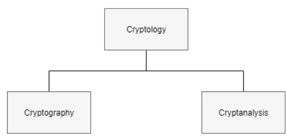
The study of Cryptosystems is known as Cryptology. It is divided into two subsystems:
1. Cryptography
[image:13.595.65.538.397.623.2]2. Cryptanalysis
Figure 1.1: Cryptosystem Block Diagram
2
messages so as to keep it confidential for information security. The word Cryptography is derived
by combining the two greek words namely Krpto meaning “Hidden” and Graphenemeaning
“Writing”. These concealed messages can be accessed only by the authorized people. It fortifies
the digital data. Cryptography is implemented with the help of mathematical algorithms which
helps in storing and transmitting the data in a particular format so that the people who has the
key to access the data can only get the information. Electronic Commerce, Secured Military
Communication, Computer Passwords etc are some of its applications. Plain text, Cipher text,
Algorithm, Key, Encryption, and Decryption are the most common terms used in Cryptography.
‘Plain text’ is the original text or message which is transmitted to the authorized recipients,
which is presented in a sealed format. ‘Cipher text’ is nothing but the unintelligible text, which
cannot be decoded. The plain text gets converted to a cipher text with the help of mathematical
computations which are defined in an ’Algorithm’. The transmitter and the receiver may have
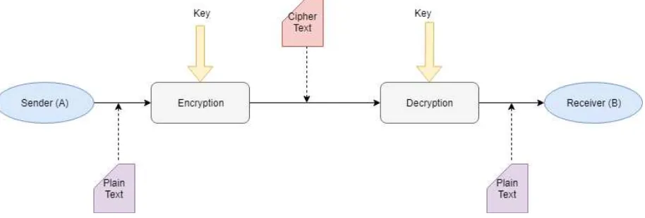
same or different ’Key’ to encrypt or decrypt the messages. The process of breaking this ’Cipher
[image:14.595.80.537.443.598.2]text’ is known as Cryptanalysis. Figure1.2shows the flow of Encryption and Decryption Process.
Figure 1.2: Flow of Encryption and Decryption Process
The main purpose of Cryptography is to serve the following information security services.
3
1. Confidentiality- This service hiddes the information from an unauthorized person. It is
basically concerned with the privacy and secrecy of data. It is a security service that
keeps the information secured from an unauthorized person. It is sometimes referred to as
privacy or secrecy. This can be achieved either through cryptographic algorithms or else
by physically securing the data. It is one of the basic information security service provided
by Cryptography.
2. DataIntegrity- Data Integrity security service recognizes any alteration to the given data.
The data might get changed or altered by an unlicensed person. The data may get modified
by an unauthorized entity deliberately or may be by chance. It basically checks whether
the data is unimpaired from the last time when it was created, transmitted and stored by
a licensed person. It cannot restrain the data from getting modified, but it gives a way for
identifying whether the data has been damaged in an unlicensed manner.
3. Authentication- Authentication identifies the source who is sending the data. The data
which is sent by the source is validated and verified first and then this information is given
to the receiver. It basically confirms that the message which has arrived at the receiver’s end
has come from the authorized sender and the data is unaltered. It also provides information
with respect to the creation and transmission of data in terms of data and time.
4. Non−repudiation- This service guarantees that an individual or person cannot decline
the possession of a foregoing activity. It guarantees that the sender of the data cannot
contradict the creation or transmission of the given data to the receiver. This service is
favorable in those circumstances where there are chances of disagreement with respect to
exchange of data. For example, a handwriting expert may be used by a legal service as a
means of non-repudiation of signatures.
4
1. Symmetric-key cryptography
2. Hash functions
3. Public-key cryptography
• Symmetric-key Cryptography: Here the symmetric key refers to a secret key. The sender
and the receiver shares the same key. The sender encrypts the plain text into the cipher text
by using this secret key and forwards the text to the receiver. The receiver on reception of
data uses the same key to decrypt the cipher text to the original text.
• Public-Key Cryptography: This technique has two keys, namely public and private key.
The public key is the one which is used by the sender to encrypt the data, which may be
freely circulated, whereas the private key associated with it is a secret key. Encryption uses
public key whereas decryption process uses private key.
• Hash Functions: No key is used in this algorithm. A fixed-length hash value is evaluated as
per the plain text that makes it impossible for the contents of the plain text to be retrieved.
Hash functions are also used by operating systems to encrypt passwords.
All the features of human life are driven by communication and information. Hence, it is
nec-essary to protect useful information from malicious activities such as attacks. Cryptographic
Attacks are of two types, namely, Passive and Active Attack. This classification is done on the
basis of the type of attacker. The main aim of the Passive Attack is to acquire unauthorized
ac-cess to information. It basically involves stealing of information. It is very difficult to identify
Passive attacks. Obstructing encrypted information and trying to break the encryption is one of
the example of passive attack. Active information alters the text by performing some process
on the information. This processing can be done by deleting the data, initiating unauthorized
5
Breaking the Cryptosystem is the main aim of the attacker and somehow retrieve the original
text from the encrypted text. So as to get the original text, the attacker just needs to obtain
decryption key. As soon as the key is known to the attacker, the cryptosystem is considered to be
broken or cracked. They are different types of attacks which are used to break the system. They
are: Ciphertext Only Attacks (COA), Known Plaintext Attack (KPA), Chosen Plaintext Attack
(CPA), Brute Force Attack (BFA), Dictionary Attack (DA), Timing Attacks, Power Analysis
Attack, Faulty Analysis Attack, etc.
Cryptography involves the study of secret communication. This study is implemented with
the help of mathematical algorithms which is termed as ’Encryption’ to encode the
informa-tion and ’Decrypinforma-tion’ to retrieve the original text from the encoded one. The different types of
Encryption include Data Encryption Standard (DES), Triple DES, RSA, Blowfish, Twofish and
Advanced Encryption Standard (AES). AES is the most widely accepted encryption standard and
is approved by the US Government to secure classified data. AES has three different key lengths
i.e, 128-bit, 192-bit or 256-bit key, making it more stronger than the 56-bit key of DES. AES
Encryption is preferred over the other encryption standards because it is more secure, faster from
hardware and software implementation point of view and also it supports larger key sizes.
This paper gives the details regarding the Design and Verification of AES Encryption using
256-bit Cipher key using SystemVerilog and UVM methodology. UVM along with the SV brings
a lot of automation, maintainability, and re-usability to the verification process. Hence, the AES
encryption module is verified using UVM and SV. The verification is carried out using hardware
implementation along with a C-model so as to compare the results from the Design Under Test
(DUT) which is AES Encryption module and Software C-model. The UVM Verification
Envi-ronment consists of different reusable components, commonly known as Universal Verification
Components. Configuration, Encapsulation and High Re-usability are some of the pros of using
1.1 Research Goals And Contributions 6
1.1
Research Goals And Contributions
The main aim of this research paper is to build a completely working modular testbench with the
help of C-model and Randomization Technique. The main contribution towards this project is
that, a layered testbench is developed using the reusable components like agent, driver, monitor,
sequencer, etc, in SystemVerilog and UVM methodology. The research goals include:
• Understanding the Encryption Algorithm and trying to implement that using 256- bit
Ci-pher key.
• To analyze Area and Power Optimization of 256 bit key size and comparing them with the
other key lengths.
• To check whether original text is being retrieved with the help of C-model.
1.2
Organization
The structure of the thesis is as follows:
• Chapter2: This chapter consists of Research Work related to AES Encryption and
Decryp-tion. It also discusses few techniques related to Key Module Generation, SBox
Implemen-tation, Area and Power Optimization.
• Chapter3: This chapter briefly describes the Block Cipher Schemes.
• Chapter4: Advanced Encryption Standard Algorithm is briefly discussed in this chapter.
• Chapter5: This chapter outlines the Block Cipher Modes of Operation.
• Chapter6: Design and Verification Methodology using the testbench components are
1.2 Organization 7
• Chapter7: Results are discussed in this chapter.
Chapter 2
Bibliographical Research
Design and Verification of a given hardware module is very important as the efficiency of a
system is the major concern now-a-days. This chapter discusses the previous work related to the
Design and Implementation of AES Encryption and Decryption process and the improvements
made in the AES hardware implementation so as to improve power, area, efficiency, etc of the
system [1].
Pipelined hardware implementation for the round keys can also be done in a parallel way
while performing the encryption process. Parallel implementation helps in reducing the delay of
each encryption round as well the delay of the input plain text [2]. The various steps involved in
the encryption process and its implementation are validated on FPGA. The time for converting
the plain text into cipher text was 200ns and device utilization is within 50% [3]. So as to
achieve high throughput and a cost effective AES module, a new module was designed for the
Key Expansion process which is known as ’on-the-fly’ key expansion structure. The throughput
achieved was 1.16Gbps with the cost of only 19476 which is equivalent to NAND2 gates [4].
Some AES applications require varible key size, so for such applications a novel architecture
genera-9
tion in one single module for different key sizes. The datapath for encryption and decryption is
also integrated. Thus the circuit area gets optimized. Security of the data and its confidentiality
plays an important role in Cryptography. Hence in [6] a design is proposed in which data is
encrypted using AES and then uploaded on a cloud. The proposed model uses Short Message
Service (SMS) alert mechanism for avoiding unauthorized access to user data. Even the security
and compression of the encrypted text can be achieved by using Arithmetic Coding along with
AES Algorithm which is discussed in [7]. The process is very simple, it encodes the data then
performs the AES Encryption and then at the receiver’s end it decodes the data. This process is
carried out at the same time. With the help of Matlab, the data is encoded, encrypted, decrypted
and decoded.
The implementation of the AES Algorithm can have different architectures namely, Pipelined,
Parallel, Rolled, Unrolled, etc. Rolled Architecture is discussed in [8]. The keys are stretched
only once and stored in a memory while the encryption process is carried out. With this
architec-ture, low power consumption was achieved of about 22.85mW. In [9], an efficient algorithm for
key pool generation by using Sudoku puzzle solving mechanism is being discussed. It creates a
pool of key for individual user. This key pool is shared only to the authorized people. It chooses
the keys randomly from the key pool while the encryption process is initiated. White- box
im-plementation is discussed in [10]. The authors have designed a toolbox which is more secure and
helpful for AES encryption process. Various mathematical Equations are illustrated in [10] so
as to give the details of the tool box implementation. An eight stage Parallel processing method
is used in SubByte transformation S-box and an eight stage parallel computation is applied in
MixColumn transformation round [11]. The architecture of this implementation is studied in
[11].
To aim real life applications, high speed and cost effective AES implementation is very much
10
validated efficiently. Memory modules such as Dual Port RAMs are used to store various
trans-formations used in AES algorithm and also the clock plays a vital role in reducing the execution
time for conversion of data to the encrypted one [12]. Throughput and area of 128, 192 and
256-bits AES have been measured in [13]. Results show that the key size is linearly increasing with
the throughput where as it is exponentially increasing with the area of the system. Low Power
Techniques can be studied in [14]. With a improved S-Box architecture, power optimization
can be easily obtained in AES algorithm. Cryptographic Algorithms are more prone to attacks.
Because of this, the original text which has to be transmitted to the receiver in encrypted format
becomes insecure. Fault-resistant implementation of AES is of utmost importance. In [15] a new
design is proposed that restricts the fault attacks on these cryptographic algorithms by verifying
differential bytes of input and output in the encryption process and the key expansion process,
respectively.
A new method is invented for performing the encryption process on an image and the details
regarding the steps for the image to get converted to an encrypted image are being discussed in
[16]. The speed of operation, efficiency, security and frequency of this new technique is also
compared. Similarly, a pipelined implementation for the image encryption and decryption can
be studied from [17] . This AES architecture increases the throughput of the system thereby
reducing the latency and improving the security and data rate. In [18], a ’look-ahead’ technique
is proposed so as to improve the speed of operation of AES Key Generator Module due which
the last round key can be available first. An efficient parallel architecture is designed in [19] for
a crypto chip. It achieves a high throughput of 29.77 Gbps in encryption.
The Dual stage Architecture for AES algorithm is proposed in [20].The power consumption
and critical path delay using the proposed architecture gives high performance. Direct Optimized
Routing (DOR) Scheme uses eleven clock cycles for encryption process whereas the Dual Stage
11
to cryptography and encryption are examined and analyzed. AES processor to generate
crypto-graphically secured information can be studied in [22]. The processor designed is resistant to
all cryptanalytical attacks and thus keeps the information secured. It removes the mathematical
equations by optimizing the AES algorithm. So far the various design implementations very
discussed. Even the designed module needs to be tested and verified. Verification using
Sys-temVerilog and UVM is more efficient compared to the traditional one as it has various add-on
features in its verification environment. SystemVerilog describes the basic language constructs,
features and use in detail. It includes several techniques and examples on how to build a
ba-sic layered test bench using Object Oriented Programming (OOP). SystemVerilog incorporates
OOP, dynamic threads, and inter-process communication [23]. UVM testbench architecture and
classes are inherited from other methodologies that have proven effective for verification of
dig-ital designs [24]. In [24], AES IP verification is carried out using UVM methodology. It is
verified using automatic testcase generation. Thus better results can be gained through automatic
testcase generation. AES Algorithm is designed and verified using SystemVerilog [25]. Even in
[25], the authors have made a comparison between the hardware and software implementation
of the AES Algorithm. The results proved in [25] shows that the hardware model is sixty times
Chapter 3
Block Cipher
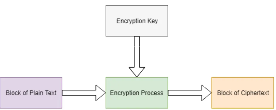
The Encryption process is carried out by taking a block of Plaintext bits and converting that into
a block of Ciphetext bits using the Encryption Key. Both the blocks of plain text and ciphertext
are of same size. Block length size is normally fixed. Block size does not directly affect the
strength of encryption process. Cipher strength depends up on the key size. The Block Cipher
Scheme can be seen in figure3.1
3.1
Block Size
Following points must be considered while selecting the block size.
• Prevent using smaller block size − For example if the size of the block is n-bits, then the
possible plain text combinations are going to be ’2n’. ’Dictionary Attack’ is initiated by
the attacker when the attacker recognizes the plain text blocks respective to the cipher text
blocks which were previously sent. The attacker builds a dictionary plain text and cipher
text pairs by and send those pairs through encryption key.
3.2 Different Block Cipher Schemes 13
Figure 3.1: Block Cipher Scheme
cipher is unproductive to manage. In such cases, plain texts must get padded before getting
encrypted.
• Multiples of 8 bit − As the data handling capacity of a CPU is a multiple of 8, the block
size/length which are multiples of 8 are preferred as it becomes more convenient from
implementation point of view.
3.2
Different Block Cipher Schemes
There is a vast number of block ciphers schemes that are in use. Many of them are publically
known. Most popular and prominent block ciphers are listed below.
• Digital Encryption Standard (DES) − It is a symmetric-key algorithm which is used for
Encrytion. Now-a-days, DES is not widely used as its block cipher identified as broken
due to small key length.
• Triple DES − Triple DES is an advancement over DES algorithm. It is a symmetric-key
3.3 Block Cipher Padding 14
keys with 56 bits each.
• Advanced Encryption Standard (AES) − It is the most widely used Encryption standard
today, and is more secured as compared to other block cipher schemes.
• RSA − RSA is a public-key encryption algorithm. This scheme passes the encrypted data
to the web. For encrypting the data, it uses pair of keys and hence, it is termed as a
asymmetric algorithm.
• IDEA − In this cipher scheme the block and key length are fixed. The block length is of
64 bits and the key length is 128 bits.
• Blowfish − Blowfish cipher scheme was developed as a substitute for DES. It is also a
symmetric scheme in which the original text gets divided into blocks of 64 bits by the
cipher and the encryption is done independently.
• Blowfish is known for both its tremendous speed and overall effectiveness as many claim
that it has never been defeated.
• Twofish − In this cipher scheme the block size is of fixed length i.e, 128 bits and key length
is of variable size. It is the advanced version of Blowfish Algorithm.
• Serpent − The speed of encryption using this scheme is slower but it is more secure as
compared to others. This scheme has a fixed block length of 128 bits and key sizes of 128,
192, and 256 bits respectively.
3.3
Block Cipher Padding
Blocks that have fixed length let’s say 32-bits or 64-bits are operated by the block ciphers. Plain
3.3 Block Cipher Padding 15
then two blocks of 64 bits are generated, so in this case block cipher padding is not required.
But if the plain text length is of 160-bits, then two blocks of 64-bits are generated with the third
block remaining with 32 bits. In this case, the third block will need padding and hence, the block
will be padded up with unnecessary information which will be equal to the block size i.e, 64-bits.
Adding redundant information to the block is known as ’Padding’. Padding makes the system
Chapter 4
Advanced Encryption Standard
4.1
Overview
This chapter briefly discusses the Federal Information Processing Standards (FIPS-197)
docu-ment which was passed by the National Institute of Standards and Technology (NIST). This
document gives the details of the Advanced Encryption Standard (AES). All the mathematical
equations related to the different AES transformations are being discussed in this chapter using
the FIPS-197 document.
The AES is a subset of the Rijndael algorithm. The Rijndael algorithm is preferred as it gives
better results with respect to security, performance, efficiency and simplicity. AES is a symmetric
cipher algorithm. In such case, a single key is used for both encrypting and decrypting the data
unlike the asymmetric ones in which there are two types of keys used namely, public and private
key for encrypting and decrypting the data respectively[26].
This algorithm processes only on fixed size of the input blocks. It supports block length of
128 bits and cipher keys with lengths of 128, 192 or 256 bits for the encryption process. Rijndael
4.2 Inputs, Outputs and the State 17
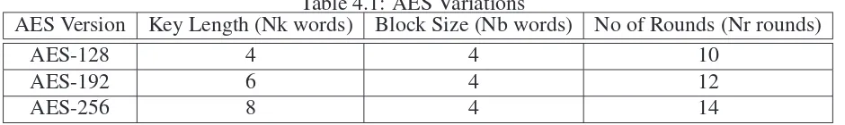
Table 4.1: AES Variations
AES Version Key Length (Nk words) Block Size (Nb words) No of Rounds (Nr rounds)
AES-128 4 4 10
AES-192 6 4 12
AES-256 8 4 14
not allow the features in AES algorithm[26]. The AES architecture is shown in figure4.1
4.2
Inputs, Outputs and the State
AES algorithm have blocks of 128 bits of input plain text and output ciphertext. It has cipher
key input is a series of 128, 192 or 256 bits. In other words the length of the cipher key, Nk, is
either 4, 6 or 8 words which represent the number of columns in the cipher key[26]. The AES
algorithm is classified into three versions based on the cipher key length. The number of rounds
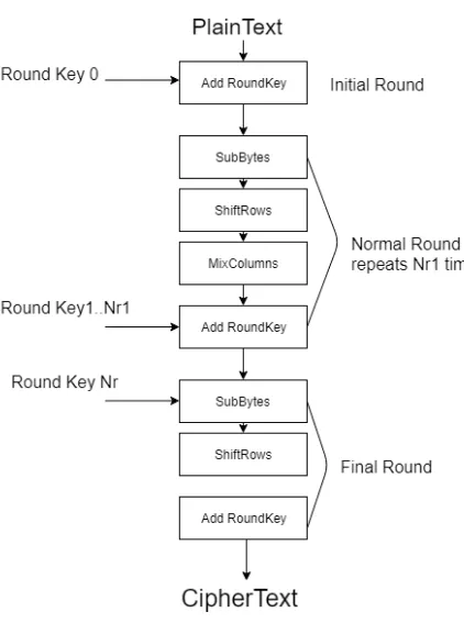
of encryption depends on the cipher key size[26]. The AES Encryption process is illustrated in
the figure4.2
The AES versions varying with key length, block size and number of rounds is tabulated in
4.1.
A byte is capable of handling the operation of the AES algorithm. Therefore, the plain text,
ciphertext and the cipher key are ordered and processed as arrays of bytes. For an input, an output
or a cipher key is denoted bya, the bytes in the following array are referenced asan , where n
ranges as follows depending on the block length and key length[26]:
• Block length = 128 bits, 0 <= n < 16
• Key length = 128 bits, 0 <= n < 16
• Key length = 192 bits, 0 <= n < 24
4.2 Inputs, Outputs and the State 18
4.2 Inputs, Outputs and the State 19
4.2 Inputs, Outputs and the State 20
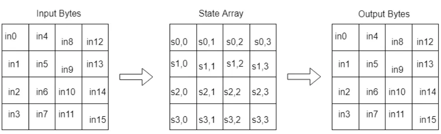
Figure 4.3: State Population and Results
The respresentation of the byte values is done by concatenating their individual bit values
be-tween braces in the order {b7, b6, b5, b4, b3, b2, b1, b0}. These bytes are considered as finite
field elements using a polynomial representation[26]:
b7x7+b6x6+b5x5+b4x4+b3x3+b2x2+b1x1+b0x=∑bixi ; where i ranges from 0 to 7
For example, {10001001} (or {85} in hexadecimal) identifies the polynomialx7+x3+1[26].
Two dimensional array of 4x4 bytes are used for processing the AES algorithm. This two
dimensional array is called as State, and any individual byte within the State is referred to assr,c
where letter ‘r’ represent the row and letter ‘c’ denotes the column. The state is filled with the
plain text at the start of the encryption process. Then the cipher performs a set of substitutions
and permutations on the State[26]. After the cipher operations are processed on the State, the
final value of the state is replicated to the ciphertext output as shown in the following figure4.3.
The input array is replicated into the State at the start of the cipher, according the following
scheme[26]:
s[r,c] =in[r+4c] f or0 ≤ r<4and0 ≤ c<4,
and at the end of the cipher the State is replicated into the output array as shown below[26]:
4.3 Cipher Transformation 21
4.3
Cipher Transformation
Either the individual bytes of the State or an entire row/column is operated by the Cipher key.
At the beginning of the cipher, the input is replicated into the State as discussed in Section 4.2.
Then, an initial Round Key addition is performed on the State. Round keys are generated from
the cipher key with the help of the Key Expansion module.The key expansion module produces
a series of round keys for each round of transformations that are performed on the State[26].
The different transformations performed on the state are same for all the AES versions but
the number of the rounds are different depending on the cipher key length. The final round in
all AES versions performs one less transformation on the State and hence it is slightly different
from the first Nr −1 rounds. Each round of AES cipher except the final round consists of all the
following transformation[26]:
• SubBytes( )
• ShiftRows( )
• MixColumns( )
• AddRoundKey ( )
4.3.1
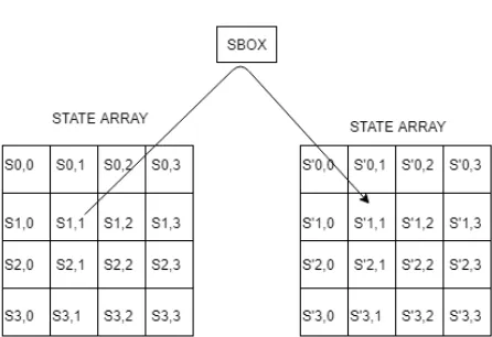
SubBytes ( ) Transformation
The 16 input bytes are substituted with the help of a S-Box table for a given design. The resultant
is a matrix consiting of four rows and four columns. SubBytes Transformation is shown in figure
4.3 Cipher Transformation 22
4.3 Cipher Transformation 23
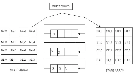
Figure 4.5: ShiftRows Transformation
4.3.2
ShiftRows ( ) Transformation
Each of the four rows of the matrix is shifted to the left. If there are any missing entries, then
they are re-inserted on the right side of row. Shift is carried out as follows −
• First row is not shifted.
• Second row is shifted one position to the left.
• Third row is shifted two positions to the left.
• Fourth row is shifted three positions to the left.
• The resultant is a new matrix consisting of the same 16 bytes but shifted with respect to
each other.
4.3 Cipher Transformation 24
Figure 4.6: Matrix Multiplication Representation
4.3.3
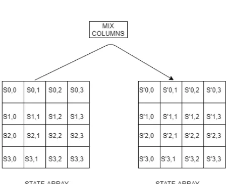
MixColumns ( ) Transformation
State Columns are operated by the Mix Column transformation. Each column is equivalent
to a finite field GF (28 ). Every column is multiplied by modulox4+1 with a fixed four-term
polynomial a(x) = {03}x3 + {01}x2 + {01}x + {02} over the GF(28 )[26]. The MixColumns
transformation can be expressed as a matrix multiplication as shown below in figure4.6:
The MixColumns transformation is shown in figure4.7.
Each column of four bytes is now transformed using a special mathematical function as
mentioned above.
4.3.4
AddRoundKey ( ) Transformation
The round key values are added to the State by simply using the XOR operation in the
Ad-dRoundKey transformation[26]. The Key Expansion module generates blocks of Nb words
which is present in every round key. The round key values are added to the columns of the
state in the following way[26]:
[s′0,c,s′1,c,s2′,c,s′3,c,] = [s0,c,s1,c,s2,c,s3,c]L[Wround+Nb+c]for 0≤c≤Nb
The 16 bytes of the matrix are now considered as 128 bits and are XORed to the 128 bits
of the round key. If this is the last round then the output is the ciphertext. Otherwise, the
resulting 128 bits are interpreted as 16 bytes and we begin another similar round. AddRoundKey
4.3 Cipher Transformation 25
4.4 AES Key Expansion 26
Figure 4.8: AddRoundKey Transformation
4.4
AES Key Expansion
Every encryption round required four words of round keys. Thus in all 4*(Nr + 1) round keys
are considered for the first AddRoundKey transformation. All the round keys are obtained from
the cipher key itself[26].
There is no limitation on the cipher key selection as per the FIPS-197 document. The Key
Expansion module expands the cipher key into the round keys. The SubWord( ) function is
same as the SubByte transformation as it uses the S-Box to substitute each of the four bytes in a
word[26]. The RotWord( ) function takes a word [a0,a1,a2,a3] as input and perform a cyclic shift
and returns the word [a1,a2,a3,a0][26]. The round constant word array, Rcon[i], contains a 32
bit value given by [{02}i−1,{00},{00},{00}] [26]. The KeyExpansion module for the AES256
where Nk=8 is slightly different as an additional SubWord function is applied to the previous
Chapter 5
Block Cipher Modes of Operation
Block cipher modes of operation permits the ciphers to encrypt the large blocks of data. It is
a setup method in which the data gets encrypted and even it does not have to adjust with the
security issues. Same key (shared key) is used for encrypting as well decrypting the data. Usage
of same key is not actually advisable but using an algorithm for uniform data inputs, uniform
ciphertext results can be obtained at the output.
Usage of shared key can help the attacker by getting the information regarding the segregation
of texts due to which the attacker can able to crack the cipher and retrieve the original text. To
avoid such situation, one can manipulate the ciphertext ouptut. This achieved by combining the
plain text with respective ciphertexts and the resultant is used as the input cipher for the next
blocks. Thus same blocks of ciphertexts are ignored from getting generated from same input
plain texts. This methodology is known as Block Cipher Modes of Operation. Different types of
5.1 ECB (Electronic Codebook) Mode 28
Figure 5.1: Encryption using ECB mode
5.1
ECB (Electronic Codebook) Mode
In this mode of operation, encryption is done by processing the plain texts individually. Even the
decryption process is carried out in the same way. Hence, it is feasible to encrypt many threads at
the same time. The ciphertext is not hazy in this mode and hence the message is not considered to
be secured as it can get easily cracked[27]. ECB is the most easy mode of operation. Encryption
process using ECB is shown in figure5.1
The encrypted text must be equal to the multiple of single block size. Hence, sometimes the
texts are stretched by adding extra one bit to it and by padding zeros to the rest of the block. The
ECB mode ciphers are more susceptible to attacks.
5.2
CBC (Cipher-Block Chaining) Mode
In this mode, the encryption process is carried out by XORing the plain text and the initialization
vector and with the help of encryption algorithm, ciphertext is generated. This ciphertext is fed
as an input to the next block of encryption. Hence, every succeeding ciphertext block depends
on the previous one. The initialization vector is of the same size as that of the plain text. This
5.3 PCBC (Propagating or Plaintext Cipher-Block Chaining) Mode 29
Figure 5.2: Encryption using CBC mode
Only one thread can be processed at a time during encryption. This mode is used in many
applications. Encryption process using CBC is shown in figure5.2
5.3
PCBC (Propagating or Plaintext Cipher-Block Chaining)
Mode
PCBC mode is same as the CBC mode. Before performing the encryption process, this mode
combines the bits from the previous and the present plain text blocks. If one output ciphertext is
impaired, then the next plain text block and all the other following blocks will get impaired. Due
to this the ciphertext will not get decrypted properly.
In this mode also only one thread can be processed at a time during encryption. Encryption
5.4 CFB (Cipher Feedback) Mode 30
Figure 5.3: Encryption using PCBC mode
5.4
CFB (Cipher Feedback) Mode
The CFB mode is identical to the CBC mode. In this mode encryption is done taking the
cipher-text data from the previous cycle and then feed the output to the plain cipher-text block. This mode is
not vulnerable to attacks. Same encryption algorithm is used at the recieving end for decrypting
the data.
If one output ciphertext is impaired, then the next plain text block and all the other following
blocks will get impaired. Due to this the ciphertext will not get decrypted properly. Only one
thread can be processed at a time during encryption[27]. Encryption process using CFB mode is
shown in figure5.4
5.5
OFB (Output Feedback) Mode
Output Feedback mode creates random bits (keystream bits) for encrypting the data. As the
random bits are generated, the operation of block cipher is identical to the operation of stream
5.6 CTR (Counter) Mode 31
Figure 5.4: Encryption using CFB mode
only done during encryption.
The disadvantage of OFB mode is that it continuously encrypts the initialization vector due
to which the plain text will not get encrypted properly[27]. Encryption process using OFB mode
is shown in figure5.5
5.6
CTR (Counter) Mode
CTR mode also creates random bits (keystream bits) for encrypting the data like the OFB mode.
As the random bits are generated, the operation of block cipher is identical to the operation of
stream cipher. ’nonce’ means the number which is distinct. The values from the counter are
combined with the nonce which gives the encrypted text as output. The nonce is equivalent to
initialization vectors used in the previous modes.
Multiple threads can be processed simultaneously. It is the most widely used block cipher
5.6 CTR (Counter) Mode 32
Figure 5.5: Encryption using OFB mode
[image:44.595.76.535.155.334.2]Chapter 6
Design and Test Methodology
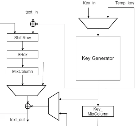
The Advanced Encryption Standard is introduced to secure the electronic data.The AES-256
pipelined cipher module uses AES algorithm which is a symmetric block cipher to encrypt the
plain text data. Encryption converts data to an unintelligible form called ciphertext. Encryption
is performed using 256 bits of cryptographic keys. The hardware module is pipelined specially
so as to perform the round transformation. As it is a pipelined design, power optimization can
be achieved and high throughput can also be gained This module is optimized for speed as it
pipeline hardware to perform repeated sequence called round. The pipelined Cipher is shown in
figure6.1
6.1
Design Implementation
• The Design for Test (DUT) is designed by using one clock , asynchronous reset, inputs
valid signal, outputs valid signal.
• Sub Bytes: As discussed earlier, it uses SBox Look-up Table (LUT ) to substitute every
6.1 Design Implementation 34
• Shift Rows: This module is used to arrange data in the state array and shifting rows of this
array.
• Mix Columns: This Module is used to perform Mix Columns Transformation as explained
in the chapter four.
• Add Round Key: This module is used for xoring input data and round key generated from
the key expansion module.
• Round: This module connects SubBytes-ShiftRows-MixColumns- AddRoundKey
mod-ules
• Round Key Gen: This module is used to handle the operation of round key generation
from input. The key generation stages must be balanced with the 4 round stages
(SuBytes-ShiftRows-MixColumns- AddRoundKey) in order to let the round key and the data meet
at the AddRound Key module Round key generation includes RotWord, SubBytes, Xor
operations using RCON which are specified in the FIPS 197 document.
• Key Expansion: The key Expansion Module is used to generate round key from cipher
key using Pipelined architecture. For AES-256, number of rounds required is fourteen, so
fourteen round key generation module will be instantiated.
• Top Pipelined Cipher: It is the top module of the design which forms rounds and connects
Key Expansion module using the pipelined architecture. It instantiates Key Expansion
module which will provide every round with round key as per the discussed algorithm.
First cipher key will be xored with plain text and then by instantiating all rounds. After
that, connect them with key expansion module, this is the final round and it does not contain
mixcolumns as per the FIPS 197 document. As the final round has only three stages a delay
6.1 Design Implementation 35
6.2 Test Methodology 36
•
6.2
Test Methodology
The Universal Verification Methodology (UVM) is the widely used in today’s era for the
veri-fication of VLSI circuits. The UVM class library helps in implementing the layered testbench
architecture. All the components of the UVM testbench are obtained from an existing UVM
class.
UVM has different simulation phases that are arranged in terms of steps of execution. They
are implemented in testbench as methods. The important UVM phases are:
• build_phase- This method is used for creating and configuring the testbench.
• connect_phase- the different sub components in a class are combined using the connect_phase
method.
• run_phase- Simulation is carried out using this method.
• report_phase- The results that are generated from the simulation are displayed using this
method.
UVM macros are used to execute some methods inside the UVM classes and variables. Those
macros are discussed as follows:
• uvm_component_utils: A new class type is filed when registers a new class type when the
class derives from the class uvm_component.
• uvm_object_utils: It is same as the uvm_component_utils, but the class is obtained from
6.2 Test Methodology 37
Figure 6.2: UVM Testbench
• uvm_field_int: The different functions like copy(), compare() and print() can be used using
this macro.
• uvm_info: This macro helps in printing messages during run time.
• uvm_error: This macro helps in sending information with error logs.
In this research paper, a AES-256 Encryption module is the Design for Test (DUT) and is
ver-ified using the UVM verification methodology. The UVM testbench is illustrated in figure6.2.
The DUT interacts with the testbench top.sv and in this way the DUT is verified using UVM
environment.
6.2 Test Methodology 38
the DUT. There is an interaction between the sequencer and the driver as the sequencer sends
packets of data which are known as transactions. The driver translates the data packets into
signals which are fed to the DUT. The DUT can only identify the data coming from the interface.
The data which is coming from the interface must be encapsulated for verification of the
stimulus. The driver converts transactions to signals, another block named as driver_out performs
the exact opposite operation of the driver. The monitor observes the interaction between the
driver and the DUT and recovers the transaction. It also helps in comparing the results fo the
DUT with the reference model. In this paper, the reference model is a C-model which is compiled
and tested. It simulates the DUT at a high level of abstraction.
The class agent has three components namely sequencer, driver and monitor. Build phase
function is defined in the agent so as to construct hierarchies and even the fucntion for connect
phase is defined for connecting the different components of the testbench. Agents are classified
into two types. They are :
• Active Agent- All the three components are a part of active agent.
• Passive Agent- It has only the monitor and the driver.
Comparator component is used to make a comparison between the outputs generated from
C-model (refmod) and the DUT. It monitors whether the signals generated from the DUT are correct
or not. The Environment class env is built by agents and the scoreboard. The simple_test which
the test class is executing the test cases. The DUT and the UVM testbench is instantiated in the
top module i.e, top.sv.
The SystemVerilog DPI interface is used for calling the functions from C/C++, Java, etc. The
SV and the foreign layers of the DPI interface are totally independent from one another. AES
Encryption C-model is used a reference model in this paper. The function int main() is defined in
6.2 Test Methodology 39
due to which the efficiency of the AES Encryption module which is the Design Under Test can
Chapter 7
Result and Discussion
The AES Encryption model is verified using the System Verilog and UVM methodology. The
functional and the code coverage was been obtained using the cover groups. Figure7.1 shows
the pipelined implementation of the AES Encryption module. Thirty clock cycles are required to
get the encrypted text.
The comparsion between the ciphet text obtained from the DUT and the C-model is shown
in figure7.2.
Proper Validation of the Cipher text was done. But with the help of traditional testbench,
comparison is done between the encrypted vectors obtained from the layered testbench. In the
[image:52.595.76.538.561.662.2]Traditional testbench, a check functionality is created for the state, key and the out which is
41
42
Figure 7.3: Traditional Testbench Code
shown in figure7.3. Here, two cases of state and the key values are fed to the design and the
expected outputs are checked. If it does not matches, then the simulator will throw an error by
displaying ’E’ else it will display ’Comparison Successful’.
The two cases of the state, key and outputs are obtained from the7.4,7.5,7.6.
The AES Encryption is also Synthesized on a different technology nodes using two different
synthesis options, RTL logic synthesis and DFT Synthesis with a full scan methodology. Area,
Power, Timing and DFT coverage analysis for the 32nm, 65nm, 180nm is tabulated in7.1
Using the Cadence Integrated Metrics Center (IMC) environment, coverage metrics were
analyzed and explored. The overall coverage obtained is 91.73% which comprises of both the
code and functional coverage. The code coverage is 91.53% where as the functional coverage
43
Figure 7.4: Output at time 9995ns
Figure 7.5: State and Key for Output at 9995ns
[image:55.595.77.573.507.693.2]Figure 7.6: State and Key for Output at 9695ns
Table 7.1: Area, Power, Timing and DFT Coverage of AES Encryption
32nm 65nm 180nm
Area
Combinational Area(µm2) 476719.24 453223.44 3225184.36 Buf/Inv Area(µm2) 29857.02 22775.04 124646.86 Non-Combinational Area(µm2) 114198.58 114186.24 879234.04 Total Area(µm2) 8424818.15 567409.69 4104418.40
Power
Internal Power (W) 8.96E-03 0.0110 0.0875
Switching Power (W) 1.613E-03 3.196E-03 0.0668
Leakage Power (W) 0.0459 2.435E-05 1.686E-05
Total Power (W) 0.0565 0.0412 0.1543
Timing Slack (ns) 17.6770 18.6740 16.1080
DFT Coverage (%) 100 100 100%
44
Chapter 8
Conclusion
This research paper presented a pipelined architecture implementation of 128-bit AES
Encryp-tion using a 256-bit cipher key. When targeting the 65nm technology, the maximum frequency of
the system is 754MHz. Power consumption for the same technology was 41.2mW after
perform-ing power analysis for the full AES Encryption process. Validation of the original text usperform-ing the
decryption function was not performed due to the fact that the results producted by the hardware
module matched the C-model. The Encrypted text obtained was cross-verified with the
tradi-tional testbench for few cases. 100% functradi-tional coverage was obtained. Security and Efficiency
are the two characteristics which are examined by the cipher designers. Hence, the challenge
is to design a cipher which provides plausible security while maintaining the efficiency for the
AES Encryption Process.
8.1
Future Work
The Latency of the pipelined implementation is thirty clock cycles. In future, work can be done
8.1 Future Work 46
user must get the plain text without errors. This can be achieved by just adding a decrypt function
in C-model. Future research can be done by designing a faster and smaller hardware design for
AES. Security and efficiency in power consumption and chip area are now being considered by
cipher designers. In some designs, efficiency needs to be sacrificed in order to achieve higher
security. Therefore, the challenge is to design a cipher which provides reasonable security while
References
[1] R. R. Rachh, P. V. A. Mohan, and B. S. Anami, “Efficient Implementations for AES
En-cryption and DeEn-cryption,”Springer, 2012.
[2] M. Mohurle and V. V. Panchbhai, “Review on realization of AES encryption and decryption
with power and area optimization,” in 2016 IEEE 1st International Conference on Power
Electronics, Intelligent Control and Energy Systems (ICPEICES), Jul. 2016, pp. 1–3.
[3] A. Kumar, M. Kumar, and P. Balramudu, “Implementation of AES algorithm using VHDL,”
in 2017 International Conference on Computing Methodologies and Communication
(IC-CMC), July 2017, pp. 732–737.
[4] Q. Cao and S. Li, “A high-throughput cost-effective ASIC implementation of the AES
Algorithm,” in2009 IEEE 8th International Conference on ASIC, Oct 2009, pp. 805–808.
[5] H. Li, “Efficient and flexible architecture for AES,”IEE Proceedings - Circuits, Devices
and Systems, vol. 153, no. 6, pp. 533–538, Dec 2006.
[6] P. Babitha M. and K. R. R. Babu, “Secure Cloud Storage Using AES Encryption,” in2016
International Conference on Automatic Control and Dynamic Optimization Techniques
(ICACDOT), Sept 2016, pp. 859–864.
References 48
coding,” in2013 International Conference on Green Computing, Communication and
Con-servation of Energy (ICGCE), Dec 2013, pp. 83–86.
[8] P. V. S. Shastry, A. Kulkarni, and M. S. Sutaone, “ASIC implementation of AES,” in2012
Annual IEEE India Conference (INDICON), Dec 2012, pp. 1255–1259.
[9] B. Indrani and M. K. Veni, “An Efficient Algorithm for Key Generation in Advance
En-cryption Standard using Sudoku Solving Method,” in 2017 International Conference on
Inventive Systems and Control (ICISC), Jan 2017, pp. 1–8.
[10] C. H. Baek, J. H. Cheon, and H. Hong, “White-Box AES Implementation Revisited,”KICS,
2016.
[11] S. S. S. Priya, P. K. Kumar, N. M. Sivamangai, and V. Rejula, “High Throughput AES
Algorithm Using Parallel Subbytes and MixColumn,”Springer, 2017.
[12] S. E. Adib and N. Raissouni, “AES Encryption Algorithm Hardware Implementation
Archi-tecture: Resource and Execution Time Optimization,”International Journal of Information
& Network Security (IJINS), 2012.
[13] ——, “AES Encryption Algorithm Hardware Implementation: Throughput and Area
Com-parison of 128, 192 and 256-bits Key,”IJRES, 2012.
[14] S. Banik, A. Bogdanov, and F. Regazzoni, “Atomic-AES: A Compact Implementation of
the AES Encryption/Decryption Core,”IJRES, 2015.
[15] J. S. Park, K. S. Bae, Y. J. Choi, D. H. Choi, and J. C. Ha, “A fault-resistant implementation
of AES using differential bytes between input and output,”Springer, 2013.
[16] P. V. Kinge, S. J. Honale, and C. M. Bobade, “Design of AES Algorithm for 128/192/256
References 49
[17] ——, “Design of AES Pipelined Architecture for Image Encryption/Decryption Module,”
IJRES, 2014.
[18] R. R. Rachh, P. V. A. Mohan, and B. S. Anami, “Implementation of AES Key Schedule
UsingLook-Ahead Technique,”Springer, 2014.
[19] S.-M. Yooa, D. Kotturib, D. W. Pana, and J. Blizzard, “An AES crypto chip using
a high-speed parallel pipelined architecture,” ELSEVIER, 2015. [Online]. Available:
https://doi.org/10.1016/j.micpro.2004.12.001
[20] K. Kalaiselvia and H. Mangalamba, “Power efficient and high performance VLSI
architec-turefor AES algorithm,”ELSEVIER, 2015.
[21] K. Zotos and A. Litke, “Cryptography and Encryption,”IJRES, 2010.
[22] L. Ali, I. Aris, F. S. Hossain, and N. Roy, “Design of an ultra high speed AES processor for
next generation IT security,”ELSEVIER, 2011.
[23] C. Spear,SystemVerilog for Verification. Springer, 2008.
[24] L. Zhu, L. Hou, Q. Xu, J. Zhi, and J. Wang, “A uvm-based AES IP verification platform
with automatic testcases generation,”Atlantis Press, 2017.
[25] B. Hakhamaneshi and B. S. Arad, “A Hardware Implementation of the Advanced
Encryp-tion Standard (AES) Algorithm Using SystemVerilog,”Springer, 2016.
[26] Specification for the Advanced Encryption Standard (AES) Federal Information Processing
Standards (FIPS) Publication 197(Nov -2001).
[27] M. Alfadel, E. S. M. El-Alfy, and K. M. A. Kamal, “Evaluating Time and Throughput at
different modes of operation in AES Algorithm,” in 2017 8th International Conference on
References 50
[28] A. Dogan, S. B. Ors, and G. Saldamli, “Analyzing and Comparing the AES architectures
Appendix I
Source Code
I.1
C - Model
1 # i n c l u d e < s t d i o . h>
2 # i n c l u d e < s t d l i b . h>
3
4 t y p e d e f u n s i g n e d c h a r b y t e ;
5 t y p e d e f u n s i g n e d i n t word ;
6
7 / / v o i d e n c r y p t _ 1 2 8 _ k e y _ e x p a n d _ i n l i n e _ n o _ b r a n c h ( word s t a t e [ ] ,
word key [ ] ) ;
8 / / v o i d e n c r y p t _ 1 9 2 _ k e y _ e x p a n d _ i n l i n e _ n o _ b r a n c h ( word s t a t e [ ] ,
word key [ ] ) ;
9 v o i d e n c r y p t _ 2 5 6 _ k e y _ e x p a n d _ i n l i n e _ n o _ b r a n c h ( word s t a t e [ ] , word
key [ ] ) ;
I.1 C - Model 52
11 word r a n d _ w o r d ( ) ;
12 v o i d r a n d _ w o r d _ a r r a y ( word w [ ] , i n t b i t _ n u m ) ;
13 v o i d p r i n t _ v e r i l o g _ h e x ( word w [ ] , i n t b i t _ n u m ) ;
14
15 e x t e r n "C" i n t main (i n t s t a t e _ m o d e l , i n t k e y _ m o d e l ) {
16 c o n s t i n t num _case = 1 0 0 ;
17 i n t b i t _ n u m ;
18 i n t i ;
19 word s t a t e [ 4 ] ;
20 word key [ 8 ] ;
21
22 / * b i t _ n u m = 1 2 8 ;
23 p r i n t f ( "AES−%d t e s t c a s e s : \ n \ n " , b i t _ n u m ) ;
24 f o r( i = 0 ; i < num _case ; i ++) {
25 r a n d _ w o r d _ a r r a y ( s t a t e , 1 2 8 ) ;
26 r a n d _ w o r d _ a r r a y ( key , b i t _ n u m ) ;
27 p r i n t f ( " p l a i n t e x t : " ) ;
28 p r i n t _ v e r i l o g _ h e x ( s t a t e , 1 2 8 ) ;
29 p r i n t f ( " \ n " ) ;
30 p r i n t f ( " key : " ) ;
31 p r i n t _ v e r i l o g _ h e x ( key , b i t _ n u m ) ;
32 p r i n t f ( " \ n " ) ;
33 e n c r y p t _ 1 2 8 _ k e y _ e x p a n d _ i n l i n e _ n o _ b r a n c h ( s t a t e , key ) ;
34 p r i n t f ( " c i p h e r t e x t : " ) ;
I.1 C - Model 53
36 p r i n t f ( " \ n \ n " ) ;
37 }
38
39 b i t _ n u m = 1 9 2 ;
40 p r i n t f ( "AES−%d t e s t c a s e s : \ n \ n " , b i t _ n u m ) ;
41 f o r( i = 0 ; i < num _case ; i ++) {
42 r a n d _ w o r d _ a r r a y ( s t a t e , 1 2 8 ) ;
43 r a n d _ w o r d _ a r r a y ( key , b i t _ n u m ) ;
44 p r i n t f ( " p l a i n t e x t : " ) ;
45 p r i n t _ v e r i l o g _ h e x ( s t a t e , 1 2 8 ) ;
46 p r i n t f ( " \ n " ) ;
47 p r i n t f ( " key : " ) ;
48 p r i n t _ v e r i l o g _ h e x ( key , b i t _ n u m ) ;
49 p r i n t f ( " \ n " ) ;
50 e n c r y p t _ 1 9 2 _ k e y _ e x p a n d _ i n l i n e _ n o _ b r a n c h ( s t a t e , key ) ;
51 p r i n t f ( " c i p h e r t e x t : " ) ;
52 p r i n t _ v e r i l o g _ h e x ( s t a t e , 1 2 8 ) ;
53 p r i n t f ( " \ n \ n " ) ;
54 } * /
55
56 b i t _ n u m = 2 5 6 ;
57 p r i n t f ( "AES−%d t e s t c a s e s : \ n \ n " , b i t _ n u m ) ;
58 f o r( i = 0 ; i < num _case ; i ++) {
59 / / r a n d _ w o r d _ a r r a y ( s t a t e , 1 2 8 ) ;
I.1 C - Model 54
61 s t a t e [ 0 ] = s t a t e _ m o d e l ;
62 s t a t e [ 1 ] = s t a t e _ m o d e l ;
63 s t a t e [ 2 ] = s t a t e _ m o d e l ;
64 s t a t e [ 3 ] = s t a t e _ m o d e l ;
65 key [ 0 ] = k e y _ m o d e l ;
66 key [ 1 ] = k e y _ m o d e l ;
67 key [ 2 ] = k e y _ m o d e l ;
68 key [ 3 ] = k e y _ m o d e l ;
69 p r i n t f ( " p l a i n t e x t : " ) ;
70 p r i n t _ v e r i l o g _ h e x ( s t a t e , 1 2 8 ) ;
71 p r i n t f ( " \ n " ) ;
72 p r i n t f ( " key : " ) ;
73 p r i n t _ v e r i l o g _ h e x ( key , b i t _ n u m ) ;
74 p r i n t f ( " \ n " ) ;
75 e n c r y p t _ 2 5 6 _ k e y _ e x p a n d _ i n l i n e _ n o _ b r a n c h ( s t a t e , key ) ;
76 p r i n t f ( " c i p h e r t e x t : " ) ;
77 p r i n t _ v e r i l o g _ h e x ( s t a t e , 1 2 8 ) ;
78 p r i n t f ( " \ n \ n " ) ;
79 }
80
81 r e t u r n 0 ;
82 }
83
84 word r a n d _ w o r d ( ) {
I.1 C - Model 55
86 i n t i ;
87 f o r( i = 0 ; i < 4 ; i ++) {
88 word x = r a n d ( ) & 2 5 5 ;
89 w = (w << 8 ) | x ;
90 }
91 r e t u r n w ;
92 }
93
94 v o i d r a n d _ w o r d _ a r r a y ( word w [ ] , i n t b i t _ n u m ) {
95 i n t word_num = b i t _ n u m / 3 2 ;
96 i n t i ;
97 f o r( i = 0 ; i <word_num ; i ++)
98 w[ i ] = r a n d _ w o r d ( ) ;
99 }
100
101 v o i d p r i n t _ v e r i l o g _ h e x ( word w [ ] , i n t b i t _ n u m ) {
102 i n t byte_num = b i t _ n u m / 8 ;
103 i n t i ;
104 b y t e *b = ( b y t e * )w;
105 p r i n t f ( "%d ’ h " , b i t _ n u m ) ;
106 f o r( i = 0 ; i < byte_num ; i ++)
107 p r i n t f ( "%02x " , b [ i ] ) ;
I.1 C - Model 56
1
2 # i n c l u d e " s b o x . h "
3
4 # i f n d e f LOCAL
5 # d e f i n e LOCAL
6 # e n d i f
7
8 # d e f i n e b y t e u n s i g n e d c h a r
9 t y p e d e f u n s i g n e d i n t word ;
10
11 # d e f i n e s u b _ b y t e (w) { \
12 b y t e *b = ( b y t e * )&w; \
13 b [ 0 ] = t a b l e _ 0 [ b [ 0 ] * 4 ] ; \
14 b [ 1 ] = t a b l e _ 0 [ b [ 1 ] * 4 ] ; \
15 b [ 2 ] = t a b l e _ 0 [ b [ 2 ] * 4 ] ; \
16 b [ 3 ] = t a b l e _ 0 [ b [ 3 ] * 4 ] ; \
17 }
18 # d e f i n e r o t _ u p _ 8 ( x ) x = ( x << 8 ) | ( x >> 2 4 )
19 # d e f i n e r o t _ 1 6 ( x ) x = ( x << 1 6 ) | ( x >> 1 6 )
20 # d e f i n e r o t _ d o w n _ 8 ( x ) x = ( x >> 8 ) | ( x << 2 4 )
21 # d e f i n e t a b l e _ l o o k u p { \
22 p0 = t 0 [ b [ 0 ] ] ; \
23 p1 = t 0 [ b [ 1 ] ] ; \
I.1 C - Model 57
25 p3 = t 0 [ b [ 3 ] ] ; \
26 }
27 # d e f i n e f i n a l _ m a s k i f ( i s _ f i n a l _ r o u n d ) { \
28 p0 &= 0 xFF ; \
29 p1 &= 0 xFF00 ; \
30 r o t _ 1 6 ( p2 ) ; \
31 p2 &= 0 xFF0000 ; \
32 r o t _ d o w n _ 8 ( p3 ) ; \
33 p3 &= 0 xFF000000 ; \
34 } e l s e { \
35 r o t _ u p _ 8 ( p0 ) ; \
36 r o t _ 1 6 ( p1 ) ; \
37 r o t _ d o w n _ 8 ( p2 ) ; \
38 }
39 # d e f i n e r o t { \
40 r o t _ u p _ 8 ( p0 ) ; \
41 r o t _ 1 6 ( p1 ) ; \
42 r o t _ d o w n _ 8 ( p2 ) ; \
43 }
44
45 v o i d e n c r y p t _ 1 2 8 _ k e y _ e x p a n d _ i n l i n e ( word s t a t e [ ] , word key [ ] ) {
46 i n t n r = 1 0 ;
47 i n t i ;
48 word k0 = key [ 0 ] , k1 = key [ 1 ] , k2 = key [ 2 ] , k3 = key [ 3 ] ;
I.1 C - Model 58
50 s t a t e [ 1 ] ^= k1 ;
51 s t a t e [ 2 ] ^= k2 ;
52 s t a t e [ 3 ] ^= k3 ;
53 word * t 0 = ( word * ) t a b l e _ 0 ;
54 word y, p0 , p1 , p2 , p3 ;
55 b y t e *b = ( b y t e * )&y;
56 b y t e r c o n = 1 ;
57
58 f o r( i = 1 ; i <= n r ; i ++) {
59 word temp = k3 ;
60 r o t _ d o w n _ 8 ( temp ) ;
61 s u b _ b y t e ( temp ) ;
62 temp ^= r c o n ;
63 i n t j = ( c h a r ) r c o n ;
64 j <<= 1 ;
65 j ^= ( j >> 8 ) & 0x1B ; / / i f ( r c o n &0x80 ! = 0 ) t h e n ( j ^=
0x1B )
66 r c o n = ( b y t e ) j ;
67 k0 ^= temp ;
68 k1 ^= k0 ;
69 k2 ^= k1 ;
70 k3 ^= k2 ;
71
72 word z0 = k0 , z1 = k1 , z2 = k2 , z3 = k3 ;
I.1 C - Model 59
74
75 y = s t a t e [ 0 ] ;
76 t a b l e _ l o o k u p ;
77 f i n a l _ m a s k ;
78 z0 ^= p0 , z3 ^= p1 , z2 ^= p2 , z1 ^= p3 ;
79
80 y = s t a t e [ 1 ] ;
81 t a b l e _ l o o k u p ;
82 f i n a l _ m a s k ;
83 z1 ^= p0 , z0 ^= p1 , z3 ^= p2 , z2 ^= p3 ;
84
85 y = s t a t e [ 2 ] ;
86 t a b l e _ l o o k u p ;
87 f i n a l _ m a s k ;
88 z2 ^= p0 , z1 ^= p1 , z0 ^= p2 , z3 ^= p3 ;
89
90 y = s t a t e [ 3 ] ;
91 t a b l e _ l o o k u p ;
92 f i n a l _ m a s k ;
93
94 s t a t e [ 0 ] = z0 ^ p3 ;
95 s t a t e [ 1 ] = z1 ^ p2 ;
96 s t a t e [ 2 ] = z2 ^ p1 ;
97 s t a t e [ 3 ] = z3 ^ p0 ;
I.1 C - Model 60
99 }
100
101 / * v o i d e n c r y p t _ 1 2 8 _ k e y _ e x p a n d _ i n l i n e _ n o _ b r a n c h ( word s t a t e [ ] ,
word key [ ] ) {
102 i n t n r = 1 0 ;
103 i n t i ;
104 word k0 = key [ 0 ] , k1 = key [ 1 ] , k2 = key [ 2 ] , k3 = key [ 3 ] ;
105 s t a t e [ 0 ] ^= k0 ;
106 s t a t e [ 1 ] ^= k1 ;
107 s t a t e [ 2 ] ^= k2 ;
108 s t a t e [ 3 ] ^= k3 ;
109 word * t 0 = ( word * ) t a b l e _ 0 ;
110 word p0 , p1 , p2 , p3 ;
111 b y t e *b ;
112 b y t e r c o n = 1 ;
113
114 f o r( i = 1 ; i < n r ; i ++) {
115 word temp = k3 ;
116 r o t _ d o w n _ 8 ( temp ) ;
117 s u b _ b y t e ( temp ) ;
118 temp ^= r c o n ;
119 i n t j = ( c h a r ) r c o n ;
120 j <<= 1 ;
121 j ^= ( j >> 8 ) & 0x1B ; / / i f ( r c o n &0x80 ! = 0 ) t h e n ( j ^=
I.1 C - Model 61
122 r c o n = ( b y t e ) j ;
123 k0 ^= temp ;
124 k1 ^= k0 ;
125 k2 ^= k1 ;
126 k3 ^= k2 ;
127 word z0 = k0 , z1 = k1 , z2 = k2 , z3 = k3 ;
128 b = ( b y t e * ) s t a t e ; t a b l e _ l o o k u p ; r o t ;
129 z0 ^= p0 , z3 ^= p1 , z2 ^= p2 , z1 ^= p3 ;
130 b += 4 ; t a b l e _ l o o k u p ; r o t ;
131 z1 ^= p0 , z0 ^= p1 , z3 ^= p2 , z2 ^= p3 ;
132 b += 4 ; t a b l e _ l o o k u p ; r o t ;
133 z2 ^= p0 , z1 ^= p1 , z0 ^= p2 , z3 ^= p3 ;
134 b += 4 ; t a b l e _ l o o k u p ; r o t ;
135 s t a t e [ 0 ] = z0 ^ p3 ;
136 s t a t e [ 1 ] = z1 ^ p2 ;
137 s t a t e [ 2 ] = z2 ^ p1 ;
138 s t a t e [ 3 ] = z3 ^ p0 ;
139 }
140 word temp = k3 ;
141 r o t _ d o w n _ 8 ( temp ) ;
142 s u b _ b y t e ( temp ) ;
143 temp ^= r c o n ;
144 k0 ^= temp ;
145 k1 ^= k0 ;
I.1 C - Model 62
147 k3 ^= k2 ;
148 b y t e * a = ( b y t e * ) s t a t e , * t = t a b l e _ 0 ;
149 b = ( b y t e * )&k0 ;
150 b [ 0 ] ^= t [ a [ 0 ] * 4 ] , b [ 1 ] ^= t [ a [ 5 ] * 4 ] , b [ 2 ] ^= t [ a [ 1 0 ] * 4 ] , b
[ 3 ] ^= t [ a [ 1 5 ] * 4 ] ;
151 b = ( b y t e * )&k1 ;
152 b [ 0 ] ^= t [ a [ 4 ] * 4 ] , b [ 1 ] ^= t [ a [ 9 ] * 4 ] , b [ 2 ] ^= t [ a [ 1 4 ] * 4 ] , b
[ 3 ] ^= t [ a [ 3 ] * 4 ] ;
153 b = ( b y t e * )&k2 ;
154 b [ 0 ] ^= t [ a [ 8 ] * 4 ] , b [ 1 ] ^= t [ a [ 1 3 ] * 4 ] , b [ 2 ] ^= t [ a [ 2 ] * 4 ] , b
[ 3 ] ^= t [ a [ 7 ] * 4 ] ;
155 b = ( b y t e * )&k3 ;
156 b [ 0 ] ^= t [ a [ 1 2 ] * 4 ] , b [ 1 ] ^= t [ a [ 1 ] * 4 ] , b [ 2 ] ^= t [ a [ 6 ] * 4 ] , b
[ 3 ] ^= t [ a [ 1 1 ] * 4 ] ;
157 s t a t e [ 0 ] = k0 ;
158 s t a t e [ 1 ] = k1 ;
159 s t a t e [