International Journal of Innovative Technology and Exploring Engineering (IJITEE) ISSN: 2278-3075,Volume-8 Issue-11, September 2019
Abstract: To make micro grid with renewable energy and to over come the technical challenges and economy base and policy and regulatory challenges . From the natural wastage we can generate the Electricity. Thus, the Electrical Power or Electricity is available with a low cost and pollution free to anyplace in the world at all times. This process divulge a unequaled step in electricity generation and this type of generation is maintain the ecological balance. We can have an uninterrupted power supply irrespective of the natural condition without any kind of environmental pollution. More influence this process relent the less production cost for electricity generation. Micro grids have long been used in remote areas to power off-grid villages, military operations or industrial projects. But increasingly they are being used in cities or towns, in urban centers. Here we try a proto type of micro grid with renewable energy sources.
Keywords : Micro grid, Renewable energy sources, Solar power ,Wind power, batterys , Voltage, AarduinoUNO , Relay switches, Inverter.
I. INTRODUCTION
P
resent days in this world it is more essential to catch up the natural power generating sources for household and limited commercial scope. we are extremely depending on coal, oil like petrol, diesel, kerosene, etc to generate the power, these sources cause more pollution to nature and living world. From the thermal and diesel power generation we get dust, ashes and poisonous gases like CO, CO2, methane and hydrocarbons etc disposals (outcome), are extremely harmful to environment. From the nuclear power plant (stations) the radioactive ashes will form ,those plants are not only rejecting immediate harmful materials, but it has a long lasting action also, since it emits radio-active radiation for a long period. Thermal power stations are the highly power generation method all over the world at present. Also we can't get natural resources like oil, coal, radio-active materials in near future. The other power generating plants like Hydro- Electricity power generating plant cannot afford much power, although it causes less pollution. Therefore, it needs crucial innovation to go for renewable energy resources for power generation. The most popular renewable power resources are solar energy and wind energy power plants . The solar energy which converts the heat energy to electric energy. Solar energy generation has a few draw backs like can't generate power in cloudy or rainy days and in night time also. So it isRevised Manuscript Received on September 05, 2019.
M. Laxmi Narayana Sagar, M.tech Student EEE, Gokaraju Rangaraju Institute of Engineering and Technology (JNTU-H), Nizampet, Hyderabad, India.
V. Usha rani, Assit. Professor EEE, Gokaraju Rangaraju Institute of Engineering and Technology (JNTU-H), Nizampet, Hyderabad, India.
mainly depending on appearance of the sun in the sky. Therefore, in the rainy season or sun's shortcoming the solar power using . people system have to remain without electricity (power) after battery gets discharged. The wind power is converted to the electrical energy .it is available in hilly areas where wind production is more in that places and it is available in all seasons. The grid which is connected with local electrical power generations and localized loads ,they are operate in normal operated conditions and connected to synchronous with the traditional wide area synchronous grid(macro grid) that grid is called micro grid. Micro grid can also disconnect to "island mode" — and the micro grid had a self governing to operates as physical or economic conditions dictate. a micro grid can definitely merge various power generating sources , specifically Renewable Energy Sources (RES) - renewable electricity , and can supply necessity power, changing between island and connected modes. Basically micro grid use the local generation ,storage of energy, power consumption, point of common coupling are the main components . Micro grids, and in general arrangement of DER units , recommend a number of functional challenges like Stability issues, Low inertia, bidirectional power flows, Uncertainty that need to be addressed in the design of control and protection systems in order to secure that the present levels of reliability are not relatively affected and the potential benefits of Distributed Generation (DG) units are fully controlled . Some of these challenges arise from incapacitate assumptions typically applied to traditional distribution systems, while others are the result of stability issues already observed only at a transmission system level.
II. SYSTEMMODELING
A. Solar system
Solar power is available in the nature with free of cost, from that solar power we can generate the electrical power by the transformation of sun light energy into electrical energy. These conversion is made with PV effect by using of solar panel. The solar photovoltaic cell (PV) is a device which converts solar light into electric current using the photovoltaic effect. In the solar panel the array of a photovoltaic cells is present .That pv cells produces direct current (DC) power with some fluctuates with the sunlight's intensity. Normally we are use the AC loads, but here we are generating DC power ,to use this dc power to ac loads we need to convert the DC power to AC power ,to convert the DC to AC we use the inverter.
Development of a Micro grid with Renewable
Energy Sources with Feedback Controller
In the solar panel multiple solar cells are connected as modules inside . In the modules p-n junctions are there are wired to form arrays, then connected to an inverter, which produces power at the required voltage, and for AC, the required frequency/phase. Solar cells, photoelectric conversion by the energy contained in sunlight into electricity are the main methods for using the solar energy. solar energy is eco friendly and clean, no pollution. The rate of using of solar power is high. In the solar energy utilization the PV power generation is plays a major role. In the photovoltaic effect of the boundary of semiconductor and changing solar radiation light energy directly into electrical energy. Solar cells are the much influential key element of the solar energy. solar cell module coupled with the power controller and other components to form a photovoltaic system device
Fig.1. Diagram of the solar pv system B. Wind system
[image:2.595.63.275.250.426.2]The traceable natural movement of the air in a specific direction is called wind energy .The wind energy is use the air flow to rotate the wind turbines to supply the mechanical power to turn electric generators and consistently to do additional work, like milling or pumping. Wind energy is converting in to mechanical energy by using the turbine propeller ,and that mechanical energy is converted into the electrical by rotating the generator shaft, at the same time we can use the mechanical power for specific tasks such as pumping water. The atmosphere is effected by the sun and variations on the earth's surface, and rotation of the earth, Mountains, bodies of water, and these things are influence wind flow patterns. Wind speed, air density, and swept area are affect on the amount of energy a turbine can harness from the wind. Most of wind turbines designed for production of electricity have consisted of a two or three blades propeller rotating around a horizontal axis.
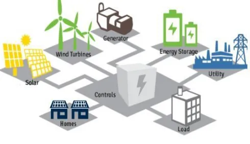
Fig.2. Diagram of the wind turbine system Here we are making the micro grid with non conventional energy sources like solar and wind power generating systems. A micro grid is a localised energy grid and it have the control capability, micro grid is a autonomously operated grid it means it may not connected to the traditional grid . The grid means the generating stations and transmission lines and distributed network and loads all are inter connected at one point .the grid can balance these connected networks. Interconnectedness means when a fault occur at a part everyone will effected. At this place a micro grid can lead the situations . A micro grid normally operates while connected to the grid, but critically it become separated and operate on its local power generation in times of calamity like tornado or power outages. A micro grid is connected by distributed generators, batteries, and renewable resources like wind generators, solar panels for power requirement. Depending on how it’s fuelled and how its requirements are handled, a micro grid might run continually.
Fig. 3. Renewable energy micro grid
III. HARDWAREDEVELOPMENT
[image:2.595.312.557.501.642.2]International Journal of Innovative Technology and Exploring Engineering (IJITEE) ISSN: 2278-3075,Volume-8 Issue-11, September 2019
A. Solar power generation
The solar power is generated through 12V,10W solar panel. The solar power is converted to electrical power through solar PV system, in these conversion heat energy is converted into electrical energy . In the solar panel there are a PV arrays those arrays are placed major role in these conversion. From the solar panel we get the dc power and that power is stored in the batteries.
Fig.5. Diagram of the solar pv panel
B. Wind power generation
The wind power is generated through the 12v wind generator .The wind turbine is connected to the generator shaft .when the wind comes with certain pressure then the turbine use that pressure and start rotation and simultaneously the generator shaft is also rotate ,then the power is generate. From the wind generator we get the dc power and the power is stored to the batteries.
Fig.6. Diagram of the wind generation From the solar and wind power the batteries will be charged , the power will flow from batteries to arduino with the help of voltage sensors .in arduino there is a programme to flow the power to inverter . The energy storage system contains two energy storage batteries.
C. Batteries
Batteries are store the electric energy ,in this paper we are using 3 batteries to store the electrical energy from the solar and wind generation . after storage they supply the energy to the inverter circuit through arudino and relays.
Batteries specifications= 12v,1.3Ah
Fig.7.Batteries
D. Arudino UNO
The Arduino UNO is an open-source hardware and software controller board. In this arduino we are using the Microchip ATmega328P microcontroller. The board is outfitted with stow of digital and analog input/output pins that may be incorporate to diverse expansion boards and other circuits.
Fig.8. Arduino UNO
E. Relay switches
Electrically the relay is an operated switch. In the relay circuit to control the single or multiple control singles it have a set of input terminals, and a set of operating contact terminals. Where it is essential to control a circuit by an separate low-power signal, or where morel circuits must be controlled by one signal at that place the relays are used. Input range of relay in this hardware kit is 30v dc ,10A and out put controlling range is 220V to 230V AC.
Fig.9.Relays
F. Inverter
The circuit which is designed for converting a DC power into a desired AC power at appropriate frequency it is called an inverter. In the inverter output voltage may be variable or fixed voltage and frequency. Depending on application this adaptation can be accomplished by restrained the turn on or turn off devices like MOSFET,IGBT ,BJT, MCT etc, or by using forced commutated thyristors. An ideal inverter output voltage is in sinusoidal waveform. But in practical inverter we can't get the output voltage waveform exactly in sinusoidal, it comes with some harmonics in non-sinusoidal waveform. . For low and medium power application square wave or quasi-square wave voltage waveform is sufficient. Low distorted, sinusoidal waveform are essential for large power application. Frequency which is came from the inverter output is determined by the rate at which the semiconductor devices are switched on and off. By Consequently control of the inverter circuitry, an alterable frequency AC output is readily provided. By using the switching variable high speed power semiconductor devices we can significantly reduce the harmonics content in the output voltage. The fuel cell, solar cell ,battery cell or other DC source are the input power for the inverter. We are use the rectifier to give the dc output in most industrial applications. The connection between a rectifier and a inverter is called a dc link. Mainly these dc links are found in VFD circuits and converter circuits. In the DC link network frequency is rectified and then filtered before being inverter to AC at adjustable frequency. Rectification is achieved by thyristor or standard diode converter circuits and inversion is accomplished from the circuit techniques. In this paper we are using single phase inverter. In this inverter there are mainly three modules like power circuit module, control circuit module, driver circuit module. The IGBT bridge circuit and rectifier unit and along with filter are connected in the power circuit module . In this Circuit 2MBI 200L- 060 IGBT circuit is
used. IGBT is used as a switch for large power applications. The power circuit get the input from the 230v supply main. The IGBTs are triggered with proper pulse sequence depending on the required output voltage. From the control circuit we can obtain the gate pulses. The control circuit module consists with dsPIC30F4013 controller circuit . The controller gives the pulses to the driver circuit which are obtain from the power circuit to controller circuit , then the inverter IGBTs gates can be triggered on and off . IGBTs output have some harmonics. By using the filter circuit the harmonics are filtered. The filtered output is connected to the load. Rectified input AC signal is fed to the IGBT through a Time delay circuit. To prevent the motor from high voltage we are use this time delay circuit due to any false triggering of the IGBT. From the inverter we get the AC output and that output gives to the AC load. In this hardware kit the input of the inverter is 12V,10A DC and the output is 220V,200W.
Fig.10. Inverter
IV. RESULTS ANDDISCUSSION
Here we can observe the wind generator out put in the below fig wind generation. It is the one of input source for proto type micro grid.
International Journal of Innovative Technology and Exploring Engineering (IJITEE) ISSN: 2278-3075,Volume-8 Issue-11, September 2019
From the 12V solar panel we are generating the power which is shown in below fig solar generation.
Fig.12.Solar generation
From the two generating units we get the below out put which is shown in below fig.
Fig.13.Overal generation
These two generations are connected parallel to the battery storage and connected to the aurdino circuit. These generations are below 7v then the arduino programme will allow the power to relay circuits from the batteries. If the generated power is more then the 7V ,those generated power is goes to aurdino to relay circuit directly. The smart grid which is develop from solar and wind power generation is shown in the below fig.
Fig.14.Proto type micro grid
V. CONCLUSION
In case of emergencies a micro grid is provides a backup , and used to cut costs, or connect to a local resource that is too small or unreliable for traditional grid use. A micro grid can lead the communities to be more energy independent and, in
some cases, more environmentally friendly. A micro grid is able to operate in grid-connected and stand-alone modes and of handling the transition between the two. In the grid-connected mode. Micro grids offer an option to balancing the need to reduce carbon emissions while continuing to provide reliable electric energy in periods of time that renewable sources of power are not available. Micro grids also offer the security of being hardened from severe weather and natural disasters by not having large assets and miles of above-ground wires and other electric infrastructure that needs to be maintained or repaired following these events. In this micro grid kit if we want to extend the range of the kit for this ratings we can add the booster circuit for inverter circuit then we get the above 200w output from the inverter.
REFERENCES
1. "A Survey of Techniques for Designing and Managing Micro grids", IEEE PES GM 2015.
2. Renewable sources of energy text book by B.H Khan.
3. Solar Cells and their Applications Second Edition, Lewis Fraas, Larry
Partain, Wiley, 2010, ISBN 978-0-470- 44633-1, Section10.2
4. Power electronics text book by P. S Bimbhra.
5. M. R. Patel, 1999, Wind and Solar Power Systems, CRC Press,Florida.
6. H. P. Garg, J. Prakash, 2002, Solar Energy Fundamentals and
Applications, 1st Edition,Tata McGraw-Hill Publishing Company Ltd,New Delhi.
7. Solar-Rains-Wind-Lightning Energy Source Power Generation System
International Journal of Computer and Electrical Engineering, Vol. 2, No. 2, April, 2010 1793-8163 by Pijush Kanti Bhattacharjee.
8. www.researchgate.net/publication/299385739_Inverter_a
nd_Other_Applications_of_Power_Electronics.
9. Principles of Power System By V.K. Mehta Rohit Mehta.
10. Microprocessor and Microcontroller By A Nagoor Kani.
11. Power System Protection and Switchgear By Badri Ram.
AUTHORSPROFILE
M. Laxmi Narayana Sagar, Student, M. Tech in power systems (EEE) from GRIET Hyderabad, B. Tech in EEE from Jaya Prakash Narayan College of Engineering(JPNC) Dharmapur, Mahabubnagar.
V Usha Rani, currently working as a Assistant professor in EEE department, GRIET -Hyderabad and doing Ph.D in KL University. She pursued B.Tech in Electrical and Electronics Engineering and M.Tech with the specialization of Power Electronics and Power Systems. She has teaching experience of 10 years. She is familiar with the softwares MATLAB, Pspice, Mi Power, Etap, PSCAD. LabView. She has published papers, Real time Web based Monitoring System for CO 2 (GWACS), Transmission Line Protection for Symmetrical and Unsymmetrical Faults using Distance Relays, Optimal Operation of Distributed Generation Unit with Micro Grid Controlling to Improve Stability and Generation Hosting Capacity, Loss Minimization and Voltage Profile Improvement with Network Reconfiguration and Distributed Generation. Her Research areas of interest are Power Systems, Renewable Energy Sources, IoT applications, Smart Grid .