International Journal of Innovative Technology and Exploring Engineering (IJITEE) ISSN: 2278-3075, Volume-8 Issue-11, September 2019
Seismic Effect on Multi Storey Building with
Different Positioning Of Floating Column
Mohammed Abdul Wasay, Suraj Baraik
Abstract: Modern multi storied buildings are being constructed with floating column at the ground floor to meet the requirements of parking or other aesthetic or utility value. Masonry buildings have proved to be most vulnerable when earthquakes strike in any part of the world. The damage caused by the earthquake cannot be eliminated but it could be mitigated by taking extra precaution. Floating columns can be constructed at any level or storey, at any point in the construction area. Seismic analysis is a major tool in earthquake engineering; this is used to understand the response of buildings due to seismic excitations in a simpler manner. Response Spectrum Analysis was used. Assumptions were made to study the seismic effect on different position of floating column for a six storied RC framed building.
Key words: Earthquakes, Floating Columns, Multi-storied buildings, Response Spectrum Analysis, Seismic Analysis
I. INTRODUCTION
Increase in urban population has led to land scarcity which is leaving no option but to go in for multi storied buildings. High rises have become the order of the day in towns also due to depletion of land and economic and utility value. The challenge for structural engineers is to design and construct multi storey buildings which pose no risk for the clients during natural disasters such as floods, earthquakes, tsunami, hurricanes and tornadoes, etc. High rises are complex system in which a number of issues have to be considered and taken into account at the time of designing them. In our study, we have taken the seismic factor upon high-rises during earthquakes. To make them earthquake proof, structural disparities, improper designing, soil and ground effect; incompatible elements should be rooted out. A sound building should have planning which takes into detail a better seismic performance. The soft storey has lesser strength and stiffness as compared to upper stories, which are stiffened by masonry infill walls. This increases the flexibility of first storey which results in extreme deflections and it leads to concentration of forces at the second storey connections and large plastic deformations. During earthquake, the energy developed is dissipated by the soft storey columns as plastic hinges are formed at the ends of columns and it transforms the soft storey into a mechanism. Collapse is unavoidable during such cases hence soft stories should be carefully planned and designed. The transfer beam which supports the floating column, transfers the load up to foundation.
Revised Manuscript Received on September 03, 2019
Mohammed Abdul Wasay, PG Student M.Tech, IARE, Hyd, TS, India Email – [email protected]
Suraj Baraik, Assistant Professor, IARE, Hyd, TS, India Email –
II. NEED OF THE STUDY
Residential and commercial buildings are readily lapping up new technology to overcome the over growing space problem or to suit their individual needs for utility purpose. For aesthetic value also floating columns are increasingly being used in multi storied building in metropolitan cities. Despite its seeming disadvantage sometimes, it cannot be overlooked in the innovative construction technology. Hence this study is undertaken to study the viability of multi storied building employing floating columns at different vantage points to gauge the following factors such as - its overall effect on the building and seismic forces acting on the floating columns at various points in seismically active areas.
III. OBJECTIVES OF THE STUDY To study the seismic behavior and the structural
performance of multi storied building with floating columns.
To study the seismic effect on building with floating columns at different positions.
To study the seismic response of building using the method of Response Spectrum Analysis using ETABS Software
IV. SCOPE OF THE STUDY
This study investigates the seismic effect on multistoried building with different positioning of floating column i.e. corner floating column, middle floating column, centre floating column and without floating column under seismic zone IV in medium type soil. The models are analyzed using ETABS 16.0.2 software. Response Spectrum Analysis is carried out in accordance with IS 1893:2016 (part 1).
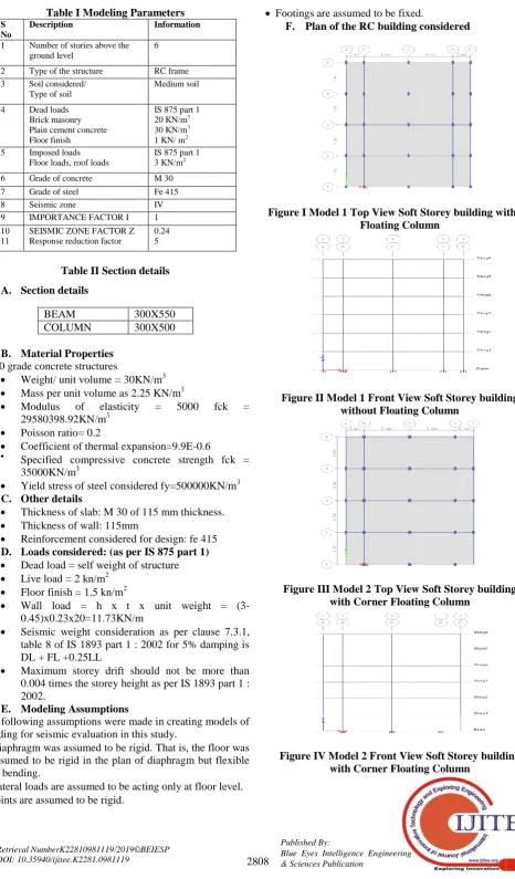
V. MODELING PARAMETERS
The present study investigates the seismic effect on multistoried building with different positioning of floating column under seismic zone IV in medium type soil. In this analysis four models are created, in case of Model 1 – soft storey without floating column, in case of Model 2 - soft storey with corner floating column, in case of Model 3 – soft storey with eccentric floating column and in case of Model 4 – soft storey with centre floating were taken.
Table I Modeling Parameters
Table II Section details A. Section details
BEAM 300X550
COLUMN 300X500
B. Material Properties M 30 grade concrete structures
Weight/ unit volume = 30KN/m3 Mass per unit volume as 2.25 KN/m3
Modulus of elasticity = 5000 fck =
29580398.92KN/m3 Poisson ratio= 0.2
Coefficient of thermal expansion=9.9E-0.6
Specified compressive concrete strength fck = 35000KN/m3
Yield stress of steel considered fy=500000KN/m3 C. Other details
Thickness of slab: M 30 of 115 mm thickness. Thickness of wall: 115mm
Reinforcement considered for design: fe 415 D. Loads considered: (as per IS 875 part 1) Dead load = self weight of structure Live load = 2 kn/m2
Floor finish = 1.5 kn/m2
Wall load = h x t x unit weight = (3-0.45)x0.23x20=11.73KN/m
Seismic weight consideration as per clause 7.3.1, table 8 of IS 1893 part 1 : 2002 for 5% damping is DL + FL +0.25LL
Maximum storey drift should not be more than 0.004 times the storey height as per IS 1893 part 1 : 2002.
E. Modeling Assumptions
The following assumptions were made in creating models of building for seismic evaluation in this study.
Diaphragm was assumed to be rigid. That is, the floor was assumed to be rigid in the plan of diaphragm but flexible in bending.
Lateral loads are assumed to be acting only at floor level. Joints are assumed to be rigid.
Footings are assumed to be fixed.
F. Plan of the RC building considered
[image:2.595.353.496.426.562.2]Figure I Model 1 Top View Soft Storey building without Floating Column
Figure II Model 1 Front View Soft Storey building without Floating Column
Figure III Model 2 Top View Soft Storey building with Corner Floating Column
Figure IV Model 2 Front View Soft Storey building with Corner Floating Column
S No
Description Information
1 Number of stories above the ground level
6 2 Type of the structure RC frame 3 Soil considered/
Type of soil
Medium soil 4 Dead loads
Brick masonry Plain cement concrete Floor finish
IS 875 part 1 20 KN/m3
30 KN/m3
1 KN/ m2 5 Imposed loads
Floor loads, roof loads
IS 875 part 1 3 KN/m2
6 Grade of concrete M 30 7 Grade of steel Fe 415 8 Seismic zone IV 9 IMPORTANCE FACTOR I 1 10
11
SEISMIC ZONE FACTOR Z Response reduction factor
International Journal of Innovative Technology and Exploring Engineering (IJITEE) ISSN: 2278-3075, Volume-8 Issue-11, September 2019
Figure V Model 3 Top View Soft Storey building with Centre Floating Column
[image:3.595.68.264.51.172.2]Figure VI Model 3 Front View Soft Storey building with Centre Floating Column
Figure VII Model 4 Top View Soft Storey building with Eccentric Floating Column
Figure VIII Model 4 Front View Soft Storey building with Eccentric Floating Column
VI. RESULTS AND DISCUSSIONS
[image:3.595.314.537.65.322.2]Response Spectrum Analysis was carried out using ETABS 2016. The results and discussions are presented for four models of six storey reinforced concrete frame models with different positioning of floating column and the results are compared in terms of base shear, storey displacement and storey drift.
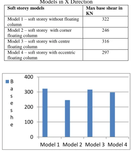
Table III Comparison of Base Shear of Different Soft Storey Models in X Direction
Soft storey models Max base shear in KN
Model 1 – soft storey without floating column
322 Model 2 – soft storey with corner
floating column
246 Model 3 – soft storey with centre
floating column
316 Model 4 – soft storey with eccentric
floating column
[image:3.595.89.248.211.327.2]297
Figure IX Comparison of Base Shear of Different Soft Storey Models in X Direction
[image:3.595.307.546.477.722.2]It is found that base shear for Model 1 – soft storey without floating column was maximum when compared to other soft storey models as shown in figure IX Maximum base shear that was observed in X direction is 322 KN. Minimum base shear observed in Model 2- soft storey model with corner floating column in X direction is 246 KN , whereas Model 3 and Model 4 have intermediate values of 316 and 297 KN respectively as discussed in Table III Table IV Comparison of Base Shear of Different Soft Storey
Models in Y Direction
Soft storey models Max base shear in kn
Model 1 – soft storey without floating column
330 Model 2 – soft storey with corner floating
column
255 Model 3 – soft storey with centre floating
column
320 Model 4- soft storey with eccentric floating
column
298
Figure X Comparison of Base Shear of Different Soft Storey Models in Y Direction
0 100 200 300 400
Model 1 Model 2 Model 3 Model 4 B
a s e s h e
0 100 200 300 400
Model 1
Model 2
Model 3
Model 4
[image:3.595.76.260.512.652.2]It is found that base shear for Model 1 – soft storey model without floating column was maximum when compared to other soft storey models as shown in figure X. Maximum base shear that was observed in Y direction is 330 KN. Minimum base shear that was observed in Model 2 – soft storey with corner floating column in Y direction is 255 KN whereas Model 3 and Model 4 have intermediate values 320 and 298 KN respectively as discussed in Table IV
Table V Comparison of Storey Displacement of Different Soft Storey Models in X Direction
Soft storey models Max storey
displacement in mm Model 1- soft storey without
floating column
10.87
Model 2- soft storey with corner floating column
13.58 Model 3 – soft storey with
centre floating column
11.45 Model 4- soft storey with
eccentric floating column
11.98
[image:4.595.314.541.48.200.2]Figure XI Comparison of Storey Displacement of Different Soft Storey Models in X Direction It is found that displacement for Model-2 soft storey with corner floating column was maximum when compared to other models considered for soft storey as shown in figure IV maximum displacement that was in XI direction is 13.58 mm. Minimum displacement was observed in Model-1 soft storey without floating column in X direction is 10.87 mm whereas in Model 3 and Model 4 have intermediate values 11.45 mm and 11.98 mm as discussed in table V
Table VI Comparison of Storey Displacement of Different Soft Storey Models in Y Direction
Soft storey models Max storey
displacement in mm
Model 1- soft storey without floating column
11.32
Model 2- soft storey with corner floating column
14.46
Model 3- soft storey with centre floating column
11.58
Model 4- soft storey with eccentric floating column
12
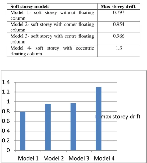
Figure XII Comparison of Storey Displacement of Different Soft Storey Models in Y Direction It is found that displacement for Model-2 soft storey with corner floating column was maximum when compared to other models considered for soft storey as shown in figure XII. Maximum displacement that was in Y direction is 14.46 mm. Minimum displacement was observed in Model-1 soft storey without floating column in Y direction is 11.32 mm whereas Model 3 and Model 4 have intermediate values of 11.58 mm and 12 mm respectively as discussed in Table VI Table VII Comparison of Storey Drift of Different Soft Storey Models in X Direction
Soft storey models Max storey drift
Model 1- soft storey without floating column
0.797 Model 2- soft storey with corner floating
column
0.954 Model 3- soft storey with centre floating
column
0.966 Model 4- soft storey with eccentric
floating column
1.3
Figure XIII Comparison of Storey Drift of Different Soft Storey Models in X Direction
It is found that storey drift for Model - 4 soft storey with eccentric floating column was maximum when compared to other models considered for soft storey models as shown in fig 6.5. Maximum storey drift that was in XIII direction is 1.3 Minimum storey drift was observed in Model - 1 soft storey without floating column in X direction is 0.797 whereas Model 3 and Model 4 have intermediate values of 0.954 and 0.966 respectively as discussed in Table VII. 0
2 4 6 8 10 12 14 16
Model 1 Model 2 Model 3 Model 4
0 2 4 6 8 10 12 14 16
Model 1
Model 2
Model 3
Model 4
max storey displaceme nt in mm
0 0.2 0.4 0.6 0.8 1 1.2 1.4
Model 1 Model 2 Model 3 Model 4
[image:4.595.50.290.174.486.2] [image:4.595.308.545.361.623.2]International Journal of Innovative Technology and Exploring Engineering (IJITEE) ISSN: 2278-3075, Volume-8 Issue-11, September 2019
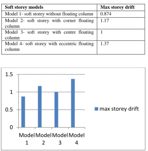
Table VIII Comparison of Storey Drift of Different Soft Storey Models in Y Direction
Soft storey models Max storey drift
Model 1- soft storey without floating column 0.874 Model 2- soft storey with corner floating column
1.17 Model 3- soft storey with centre floating column
1 Model 4- soft storey with eccentric floating column
1.37
Figure XIV Comparison of Storey Drift of Different Soft Storey Models in Y Direction
It is found that storey drift for model 4 soft storey with eccentric floating column was maximum when compared to other models considered for soft storey models as shown in figure 6.6 maximum storey drift that was in XIV direction is 1.38 Minimum storey drift was observed in model 1 soft storey without floating column in Y direction 0.874 whereas in Model 3 and Model 4 have intermediate values of 1.17 and 1 respectively as discussed in Table VIII
VII. CONCLUSIONS
From the parametric study carried out the following conclusions were obtained –
1. Base shear is maximum in Model -1 soft storey frame without floating column which was observed in X direction as 322 kn and Y direction as 330 kn. Base shear is minimum in Model - 2 soft storey with corner floating column which was observed in X direction as 246 kn and Y direction as 255 kn, whereas Model 3 and Model 4 have intermediate base shear values.
2. Storey displacement is maximum in Model - 2 soft storey with corner floating column which was observed in X direction as 13.58 mm and Y direction as 14.46 mm. Storey displacement is minimum in Model - 1 soft storey without floating column was observed in X direction as 10.87 mm and Y direction as 11.32 mm, whereas Model 3 and Model 4 have intermediate storey displacement values.
3. Storey drift is maximum in Model - 4 soft storey with eccentric floating column which was observed in X direction as 1.3 and Y direction as 1.37. Storey drift is minimum in Model - 1 soft storey without floating column which was observed in X direction as 0.797and Y direction as 0.874 whereas Model 3 and Model 4 have intermediate have intermediate storey drift values.
4. The resistance of soft storey with corner floating column is minimum when compared to other types of models and is maximum in soft storey without floating column. Hence, it
can be concluded that soft storey with corner floating column is not suitable for earthquake prone areas.
REFERENCES
1. Agarwal, Pankaj, Shrikhande, Manish. 2010. Earthquake resistant design of structures. PHI Learning, New Delhi. 634pp.
2. Keerthi Gowda, B. S., Tajoddeen, Syed. 2014. Seismic analysis of multistorey building with floating columns. Proceedings of ACIDIC-2014 Seismic analysis of multi-storey building with floating columns 528-535pp
[https://www.researchgate.net/publication/282905209_SEISMIC_AN ALYSIS_OF_MULTISTOREY_BUILDING_WITH_FLOATING_C OLUMNS] Accessed on 28-02-2019
3. Rohilla, Isha, Gupta, S. M., Saini, Babita. 2015. Seismic response of multi-storey irregular building with floating column. Intl J of Research in Engg and Tech. Volume: 04 Issue: 03 Mar-2015. 506-518 pp
[https://ijret.org/volumes/2015v04/i03/IJRET20150403086.pdf] Accessed on 28-02-2019
4. Waykule .S.B. et al. 2017. Comparative Study of floating column of multi storey building by using software. Intl. J of Engg Research and Appl Vol. 7, Issue 1, January 2017, 31-38 pp.[
https://www.ijera.com/papers/Vol7_issue1/Part-3/E0701033138.pdf] Accessed on 11-03-2019
AUTHORS PROFILE
Mohammed Abdul Wasay is a student of M Tech (Structural Engineering) in Institute of Aeronautical Engineering, Dundigal, Hyd, T S. He has interest in research in Earthquake Resistant Design of Buildings, Concrete Technology. He has done his B Tech in Civil Engineering from Nawab Shah Alam Khan College of Engineering and Technology Hyd, T S.
Suraj Baraik is Assistant Professor in the Department of Civil Engineering in Institute of Aeronautical Engineering, Dundigal, Hyd, T S. He has done his B Tech from Chennai and M Tech from JNTUH. He has 4 years of experience in teaching UG and PG students. He has interest in teaching Foundation Engineering and Advance Reinforced Concrete Structures. His area of specialization is Structural Engineering. He has published papers in reputed national and international journals.
0 0.5 1 1.5
Model 1
Model 2
Model 3
Model 4
[image:5.595.49.291.77.324.2]