Abstract: The Nanogrid utilizes renewable energy sources, e.g. Solar PV, Wind, etc; which are stochastic in nature. Due to this nature, power reliability is the main issue. To increase the reliability of the power supply and proper utilization of the available resources, Nanogrid should either connected to the utility grid directly or it must have the proper energy storage system. Energy storage system fills the gap between consumers demand and renewable power generation; which is very important issue in technical and economical consideration. The Nanogrid gives new hope of ray to the people living in off grid areas. By using energy storage system we can increase their living standard and enhance socio-economical development. This paper proposes the selection of the proper energy storage device and its calculation, control strategy also suggested for protecting storage device from over voltage and deep discharge.
Index Terms: Energy storage devices, Nanogrid/ Microgrid, renewable energy sources, stability and analysis.
I. INTRODUCTION
Nanogrids are becoming more famous now a days due to many reasons. These use, combination of the different distributed generation units such as solar PV cell, wind, biogas, biomass, fuel cells and energy storage system [1- 5]. Nanogrid is more famous in rural areas, as it uses the available resources for the generation of the electricity. Due to government policies of the “solar roof top system” and power to each home [6], Nanogrid is best option for individual home or small system even in the urban areas [7-8].Its operation is also flexible; it can operate in grid connected mode or in islanding mode[9-10]. It can operate on different frequencies, other than conventional or on DC supply [11]. The best part of the Nanogrid is that it can be operated in the combination with other Nanogrid to form a microgrid [12]. Nanogrid is small part of the microgrid or microgrid is formed with the combination of many Nanogrids. The difference in the microgrid and Nanogrid is their operating power level. The Nanogrid is up to 10kW and microgrid is from 1 MW to 100 MW. As the Nanogrid uses renewable energy sources which are stochastic in nature, power reliability is the main issue. When generation unit is generating power it should be used at that time only, but this is not possible every time. To increase the reliability of the power supply and proper utilisation of the available resources either Nanogrid should connect to the grid directly or it must have the proper storage system. The modern power electronics plays an important role in the proper utilisation and protection of these stochastic renewable energy sources [13].
Revised Manuscript Received on September 03, 2019
S. P. Jolhe, Electrical Engineering, Government College of Engineering, Nagpur, India.
G. A. Dhomane, Electrical Engineering, Government College of Engineering, Chandrapur, India.
M. D. Karalkar, Electrical Engineering, Priyadarshini J. L. College of Engineering, Nagpur, India.
India is world’s third largest electrical energy production country with generation capacity of 350.162 GW [14]. Although so huge generation of electric power, still power companies are not able to fulfill the requirements of the consumers. Fig 1 shows the electric power supply crush in India, which clearly indicates that the power is short. "Power for All", scheme is launched by Government of India for supplying electric power to all the people in the country by March 2019 [6]. With this scheme India will find the unexplored electrical power available in the country. One of the ways is solar roof top scheme for Solar Home System (SHS) and small commercial buildings or industries [15-16].
Fig. 1. Indian supply power defeat
II. SYSTEMCOMPONENTS
A. Solar PV Panel
[image:1.595.323.527.312.448.2]According to the Indian climate, most relevant renewable, affordable and low maintenance source is solar PV system. A photovoltaic system is made up of several photovoltaic solar cells. A single PV cell can generate very small power about 1 or 2 W, depending upon material and type of construction. For higher power output, different connection combinations of PV cells are used like series, parallel and series - parallel.
Fig. 2. Efficiency of different material solar PV pannel
S. P. Jolhe, G. A. Dhomane, M. D. Karalkar
Fig 2 shows the efficiencies of the different material solar PV panel modules. The efficiency of the panel is an important issue in number of panel required for the particular load or home and hence other factors like space required, installation material, and maintenance and hence cost.
TABLE I. SOLAR PANEL MATERIAL AND EFFICIENCY
Solar Cell
Type Advantages
Disadvanta ges Efficiency -Rate Thin-Film: Amorphous Silicon (A-SI) Production is Simple & flexible; costs is relatively low Small lifespan &warranties ~7-10% Poly-crystallin
e (p-Si) Price is low
Small lifespan; Sensitive to high temperatures & slightly less space efficiency ~15% Mono-crystalli ne (Mono-SI) Efficiency is high; life-time value is high optimised for commercial use
Expensive ~20%
Concentrated PV Cell (CVP)
Very high efficiency & performance Solar tracker & cooling system needed (to reach high efficiency rate) ~41%
[image:2.595.55.275.467.676.2]The efficiency of the solar panel varies from 7% to 41%. As the efficiency increases cost also increases exponentially. So while selecting the panel one has to optimize between cost and efficiency.
Fig. 3. Nanogrid System
B. Controller
Renewable generation is normally stochastic in nature, so as to get proper electrical supply controller is needed. Due to revolutionary changes in the power electronics, many options are open for the output of system i.e. it can operate on the different frequency or on DC grid system [11].
Following are the options 1.DC power supply
a) High voltage DC (HVDC) b) Low Voltage DC (LVDC) 2.AC Power supply
a)16 2/3 Hz b)50 Hz c)400- 500Hz d)20 KHz
Conventional residential loads are designed to work on AC voltage. For the particular electronics load the conversion is made from AC to DC. Due to inherent losses in conversion system the conversion is not hundred percent. So one step DC and AC converter (Switching Boost Inverter) is used in this paper.
C. Energy Storage System
The most important part of the Nanogrid / Microgrid is Energy Storage System. Electrical energy produced by renewable energy sources cannot be directly feed to the load. The energy storage device acts as a mediator in between renewable energy sources like solar, wind etc. and the load to be supplied. This aspect is very important in consideration of technical and economical issues. For charging, discharging and control of energy storage devices, power electronics plays an important role. With the help of power electronics devices energy storage system are capable of reducing the fluctuations due to load, peak power cut off and also in making the renewable energy sources an efficient energy system.
Following are the storage options Battery
Super capacitor
Super Conducting magnetic energy storage (SMES) 1. Batteries
The most common and readily available choice of the electrical storage system is battery. Many factors are affecting the selecting suitable battery. The selection of the specific battery for the specific application is mainly depends on physical properties, while other decisions will be much more difficult and may involve making trade-offs between desirable and undesirable battery features.
In battery subsystem design, many considerations are included like:
How many batteries should be connected in series/ parallel?
What should be over-current setting?
Setting requirement in overcharging or under drained. What should be disconnecting requirements?
Selection of the proper wire sizes and types.
Depending upon the requirements of the system the energy output from the renewable energy sources is stored in a battery or in a battery bank [17]. The primary functions of the battery in an integrated power system are
i.Storage: When PV array is producing electrical energy , it should be stored
ii.Supply energy on demand: Whenever needed by the consumer the electrical energy should be available to electrical loads
iii.Quality of supply: Stable voltages and currents should be
supplied to
‘smoothing out’ transients.
iv.Supply high peak operating currents: If needed by electrical loads or appliances, battery should provide the high peak operating currents or surge.
Calculation of the battery
For calculating the size of the battery or battery bank for the Nanogrid/ microgrid application, load on the grid should be calculated first. Following Table II shows different loads in particular Nanogrid.
TABLE II. DAILLY LOAD CONSUMPTION
S N Applianc e Uni t
Wattage Usage (h/d)
Demand (Wh/d)
1 CFL light 6 7 4 168
2 TV 1 100 3 300
3 Mobile
Charger
1 3 4 12
4 Mini
Freezer
1 27.4 24 658
5 Laptop 1 65 2 130
6 Water
pump
1 1000 0.5 500
7 Mixture 1 500 0.5 250
Total 2, 018
The next is the choice for storage that how many days backup or storage capacity required? It depends upon consumer to consumer. Generally 2 or 3 days back up is taken. Let for our case take 3 days backup.
2018 *3 = 6, 054 watt-hour
So 6, 054 watt-hour/24 volts = 252.25 Ampere hours (Ah) (battery bank used voltage 24V; Ampere hours can be reduced to half if 48 voltage is used).
Discharge of battery also plays an important role in calculation.
Assuming 50% discharge of battery so 252.25 *2 = 504.5 Ah capacity of battery bank is required.
2. Super capacitor
The super capacitor is basically developed for the military application. In recent days, it is used commercially (e.g. Power quality, laptops and cell phones etc.). The best thing of the super capacitor is; it requires very small space. Compared to metallic foil type capacitor, super capacitors having 1000 times smaller dimensions. So it has higher energy density as compared to common capacitors and batteries. Like usual capacitor, Super capacitor also uses two layer plates. Therefore, like most capacitors, this storage system also ideally suited for high power application and has very long cyclic life and, short-discharge applications. The storage capacity of any capacitor is proportional to the square of its voltage.
Like the battery cell, recently super capacitors are also operating in 2 V range. Thus cells are connected in faction of series, parallel or series-parallel combination to form module. The voltage of this module is restricted to 200 to 400 volts due to reliability issue. Super capacitors are commercially available having range of 100kW and discharge time of less than 1 to 10 seconds. The research is going on for the high voltage utility applications of super capacitor [18-19].
Calculation of the super capacitor battery Let’s take an example:
6 capacitor are connected in series Each capacitor is of 220F and 2.3V
Total capacitance and voltage = 37F and 13.8V
Energy stored at 13.8 V is 3485 Joules (E = 0.5CV2) & 0.968Wh
Therefore each capacitor stores 162 mWh with 2.3 V 3. Super conducting magnetic energy storage (SMES)
[image:3.595.48.289.168.341.2]Generally electrical energy is stored in other forms of energy such as chemical, mechanical, etc. The only technology which can store electrical energy in the form of electrical energy is known as super conducting magnetic energy storage (SMES). In this technology electrical energy is stored in the form of direct electrical current.
Fig. 4. Super conducting magnetic energy storage (SMES)
This system consists of basic three parts: 1) Superconducting magnetic coil 2) Power conditioning equipments 3) Refrigeration system
The principle of storing electrical energy in SMES is in the form of an electromagnetic field which is produced by DC electric current flowing through a superconducting coil. Under ordinary conditions losses result from the resistance of the wire, and energy must be supplied continuously to maintain the current. But if the wire/ coil were made up of superconducting material and kept at the required low temperature, resistance losses would be very small. Electrical energy supplied as direct current to the coil would then be stored in the electromagnetic field. By attaching this coil to the load the stored energy could be recovered as electrical energy. This system has high efficiency up to 98% when operated with 17ms.
Coil Diameter 1000m – 1000MW for 5Hrs Coil Diameter 1 m – 1MW for 1 second.
The major problem with this storing system is the environmental issues and high initial cost [19- 20].
III. OPERATION
Fig 5 shows all powers of the system – input solar power, AC and DC load and charging and discharging of the battery. The solar power depends on the
radiation available at that time. Radiation curve is taken as trapezoidal. Same
Refrigeration Unit
Power Switching and
curve will be followed by the solar PV cell for generation.
The system will operate with three different modes
1. PG > PL
2. PG < PL
3. PG + PB < PL
Where
PG- Power genrated by Renewable Enrgy sources
PL – Power taken by the load
PB – Power of battery
Mode 1 : PG > PL
In this mode power generation unit genrate the more power than the requirment of the load. In this paper solar generation is taken; the power will incease up PG > PL + PB(Charging), once it reaches PG = PL + PB(Charging), Solar PV generation enters in constant power generation and variation in PB will be there. Battery is initially get charged from the solar PV generation available in the low load duration. In the Fig. 5, battery is getting maxium power during point A to B, during B to C load increases so battery is still charging but power taken by battery is less than previous section. When battery gets fully charged over voltage protection system will be activated and battery is disconncected from the system.
Mode 2: PG < PL
As seen in the above mode 1 ; solar power generation now enters in the constant power generation mode so now chage in the power will be observed. As the load is more than that of generated power, battery will provide only surplus power. In Fig 5, battery starts discharging from point D. As the load increases further it will be supplied by the battery.
Mode 3: PG + PB < PL
IV. CONTROLSTRATEGY
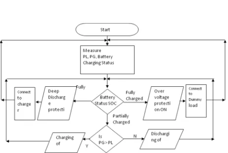
As discussed above the control strategy for the protection and proper operation of the battery is design according to requirement of the system. The overvoltage and deep-discharge cut off values were calculated and translated from voltage cut-off values to State of Charging( SOC) values. Fig 6 shows complete operation and control strategy for the battery. Initially batertty will supplying power as the solar is not yet in generation mode, from point A to B batttery is in charging mode and no other load is connected to grid, so all generated power is consumed for battery charging. At point B, over voltage protection is activated and battery get disconnected from the charging . During point B and C, power supplied by the solar PV is drooped down. This power can be utilised to charge the other battery in the grid. Literature [21] claims more than 30 % of the energy generated was dumped. From point C to D, load is supplied by the solar PV generated power, but as the load increases, power demand increases, so battery is also supplying power. At this time solar PV
generation is in constant power generation mode. At point D load is still increased, which is beyond the capacity of the battery plus solar generation, so power is taken from the other Nanogrid.
In this situation there are other options of the load shedding i.e. low priority load should be switched off. At point E battery deep discharge protection is ON and battery gets detached from the grid. All loads will be supplied by the other Nanogrid.
[image:5.595.66.532.49.526.2]FIG. 6 Control strategy operation
Fig. 7 Flowchart of battery control strategy
V. CONCLUSION
The paper introduces the flexible control strategy for the energy storage device, e.g. battery, for the Nanogrid/ microgrid. The over voltage and deep discharge control strategy was designed and developed for the Nanogrid / Microgrid. The system stability is maintained by strategic control of the energy storage device. The effectiveness of the proposed strategy for the control of energy storage device was
proved by the simulation results. The power can be exchanged between adjacent Nanogrid to form the microgrid and that to without any extra communication link. Furthermore Nanogrid manages available power in very effective way; it utilizes the Solar PV generated power to its maximum capacity.
The Nanogrid with energy storage devices gives new hope of ray to the people living in off
[image:6.595.68.531.317.629.2]oto
increase their living standard and enhance socio-economical development.
If the Nanogrid is operated in the stand alone mode then there is considerable amount of energy available which is not been used, as shown in Fig 6 between point B and C. This energy can be generated and sold to grid, which will enhance the economics of the owner.
REFERENCES
1. Bryan, J., Duke, R., Round, S., “Decentralized generator scheduling in a nanogrid using DC bus signaling,” IEEE Power Engineering Society General Meeting, June 2004, vol. 1, pp. 977–982
2. J. Sch¨onberger, R. Duke, and S. Round, “DC Bus Signaling: A Distributed Control Strategy for a Hybrid Renewable Nanogrid,” IEEE Transactions on Industrial Electronics, 2006 , Vol. 53 , Issue: 5, pp- 1453 - 1460
3. Boroyevich D., Cvetkovic I., Dong D., Burgos R., Wang F., Lee F. , “Future electronic power distribution systems a contemplative view,” 12th international conference on optimization of electrical and electronic equipment, IEEE 2010, p. 1369–80.
4. Latha SH, Chandra Mohan S.,“Centralized power control strategy for 25 kw nano grid for rustic electrification,” Int. Conf. Emerg. Trends Sci. Eng. Technol., (IEEE); 2012, p. 456–461.
5. Kirthiga, M.V., Daniel, S.A., Gurunathan, S., “A methodology for transforming an existing distribution network into a sustainable autonomous micro-grid”, IEEE Trans. Sustain. Energy, 2013, 4, (1), pp. 31–41
6. Power for All, Ministry of power, Government of India
7. S.P. Jolhe, G. A. Dhomane M. D. Karalkar, “Solar Home system as the basis or bottom up grid,” International Conference on computing, communication, information security and analytics (ICCCISA-2019) 8. Leena Chandran-Wadia, Shruti Mahajan Deorah, Sameer Nair and
Anshuman Lath, “Prospects for Electricity Access in Rural India Using Solar Photovoltaic Based Mini-Grid Systems,” Decentralized Solutions for Developing Economies, chapter 5.
9. Goikoetxea, A., Canales, J.M., Sanchez, R., Zumeta, P., “DC versus AC in residential buildings: efficiency comparison,” IEEE EUROCON Conf., July 2013, pp. 1–5
10. Liang, C., Shahidehpour, M., “DC microgrids: economic operation and enhancement of resilience by hierarchical control,” IEEE Trans. Smart Grid, 2014, 5, (5), pp. 2517–2526
11. S. P. Jolhe, M. D. Karalkar, Dr. G. A. Dhomane., “Transmission Options for Standalone system,” IEEE sponsored 3rd International Conference on Electronics and Communication Systems (ICECS-2016).
12. Daniel Burmester, Ramesh Rayudu, Winston Seah, Daniel Akinyele, “A review of nanogrid topologies and technologies”, Renewable and Sustainable Energy Reviews 67 (2017) 760–775.
13. Cvetkovic I, Dong D, Zhang W, Jiang L, Boroyevich D, Lee FC., et al. “A testbed for experimental validation of a low-voltage DC nanogrid for buildings,” 15th International Power Electronics and Motion Control Conference, IEEE 2012; p. LS7c.5-1–LS7c.5-8.
14. CEA report Feb 2019.
15. Nayeemur Rahman, Maria Islam, Md. Ziaur Rahman Khan, “Power Sharing between Solar Home Systems by Smart Control of Power Flow’, 10th International Conference on Electrical and Computer Engineering (ICECE), 2018
16. S.P. Jolhe, G. A. Dhomane M. D. Karalkar, “Smart Home,” National Conference on Clean and Green Energy, 2016
17. S. Sumathi, L. Ashok Kumar, P. Surekha, “Solar PV and Wind Energy Conversion Systems.” Book : Springer International Publishing 18. Arbizzani C., Mastragostino M., Soavi F. , “New trends in
electrochemical supercapacitors”, J Power Sourc 2001; 100:164-170 19. Schainker R B., “Executive overview: energy storage options for a
sustainable energy future”, Proceedings of the Power Engineering Society general meeting, vol. 2: 2004. p. 2309–14.
20. Rahman F, Rehman S, Arif M, Majeed A., “Overview of energy storage systems for storing electricity from renewable energy sources in Saudi Arabia”, Renew Sustain Energy Rev 2012;16:274–83 21. Hannes Kirchhoff, “ Identifying Hidden Resources in Solar Home
Systems as the Basis for Bottom-Up Grids,” Decentralized Solutions for Developing Economies, chapter 2
AUTHORSPROFILE
First Author personal profile which contains their education details, their publications, research work, membership, achievements, with photo that will be maximum 200-400 words.
Second Author personal profile which contains their education details, their publications, research work, membership, achievements, with photo that will be maximum 200-400 words.
M. D. Karalkar -. Received the Bachelor’s degree in Electrical Engineering and Master’s degree in Electrical Power System from Dr. Babasaheb Ambedkar University, (DBATU), Lonere, Raigad, India, in 2001 and Bharati Vidyapeeth, Pune in 2012 respectively. Since 2017, she has been working as an Assistant Professor in Priyadarshini J L College of Engineering, Nagpur India. Her research interests include distributed generation and power electronics.