Abstract:In this paper,CPW fed Trapezoid shape patch antenna is analyzed and investigated for Wireless Local Area Network (WLAN) application. The proposed antenna is fabricated on FR4 substrate having dimensions of 19mm ×21.2mm ×1.6mm. It resonates at 5.44 GHz frequency with peak return loss of 25.8 dB. The parametric study of proposed antenna is carried out to understand the effect of different values of ground plane on the impedance bandwidth, return loss of the antenna andalso to optimize the antenna parameters. The CPW-fed is used to enhance the bandwidth and to reduce the return loss of the antenna. The importance of different design parameters like current distribution, S-parameter, gain, and radiation pattern are studied. The results of the proposed antenna are useful for WLAN Application.
Index Choice —Bandwidth,CPW-feed, Patch Antenna, WLAN and Return loss.
I. INTRODUCTION
In the modern times with the rapid growth of modern wireless communication the size of wireless devices became smaller and smaller which demands for compact size multiband antennas. The antennas with wideband and multiband characteristics are the need of today’s wireless communication systems. Among all the communication standards like for Wi-Fi, LTE or WLAN communication components the antenna plays a very important role and is an irreplaceable element[1]. The modern systems have the capability support multiple wireless applications and can be operated on different frequency bands simultaneously.These factors attract the researchers towards the microstrip patch antennas due to their low cost, less weight, compact size, low profile and ease of fabrication. Microstrip antenna consists of two important parts a radiating patch and a ground plane. These antennas are also called as half wavelength structures and can operate at fundamental resonance mode[2]. These antennas have an advantage that they can be easily operate in dual-band and multi-band applications.
In the open literature, there are various techniques available to design triple-band or dual-band antennas in the existing published literature. There are many planar antennas available based on microstrip line feed for dual-band and multi-band operations[3]. In[4], a diamond shaped patch antenna with multiple strips is proposed for wireless
Revised Manuscript Received on June 15, 2019.
Pooja, Electronics & Communication Engineering, Chandigarh University, Mohali, Punjab, India .
DavinderParkash, Professor,Electronics & Communication Engineering, Chandigarh University, Mohali, Punjab, India.
Harbinder Singh, Electronics & Communication Engineering, Chandigarh University/, Mohali, Punjab, India.
application. In[5], a CPW fed two umbrella printed wideband antenna is studied for WLAN/WiMAX/UWB applications. A compact microstrip-fed rectangular shaped ring antenna embedded with three inverted S-shaped and inverted C-shaped strips proposed for WLAN, Wi-MAX and UWB applications[6].
In the recent years, a compact multiband microstrip antenna is proposed in which multiband operation is achieved by using inverted L and T shaped parasitic elements[7]. In [8] a new approach is apply, complementary split ring resonator is used to obtain multiband frequencies A compact Microstrip slot triple band antenna is reported in [9] which is suitable for WLAN/WiMAX applications. A[10] new multiband Integrated wideband antenna is presented for Bluetooth/WLAN application with measured fidelity factor of 0.82. In[11], a multiband slot loaded dipole antenna is reported for WLAN and LTE-A application with a gain of 4.09dB.
In this paper a compact simple and flexible CPW-fed trapezoid shape antenna is investigated. The proposed antenna offers around 1 GHz impedance bandwidth from 4.9 GHz to 5.91 GHz and cover WLAN frequency band of 5.2GHz, and 5.8GHz.The remaining part of the paper is organized in such way that: Section II presents the antenna design and its configuration, Section III discusses the simulation results of the proposed antenna and Section IV concludes this work.
Fig.1: Proposed antenna Geometry
II. ANTENNADESIGN
The design and schematic of the proposed antenna is shown in Fig. 1.The antenna is a CPW-fed trapezoid shape
Trapezoid Shape Patch Antenna for WLAN
Application
Pooja, Davinder Parkash, Harbinder Singh
W
L L2
L3
Wt L1
Lg
patch antenna for WLAN application. The evolution of trapezoid shape antenna is shown in Fig. 2. The antenna geometry consists of two trapezoid shape slots and an E shape cut on the right side. The proposed antenna structure is developed from a traditional microstrip antenna with the aim of attaining compactness, improving the gain, bandwidth of the antenna and introducing the multiband operation. A cost effective dielectric material FR4 having dielectric constant of 4.4 and a thickness of 1.6mm is used for printing the microstrip antenna. The antenna parameters are optimized by using Zeland IE3D simulation tool.The values of different parameters of the proposed design are shown in table1
(a) (b)(c)
Fig.2: Antenna evolution of proposed trapezoid shape antenna
The trapezoid shape patch antenna is fed by using CPW transmission of a 50 Ω impedance line of width Wt, which helps in simplifying the fabrication process by considering ground plane of Lg×Wg and radiating patch on one side of patch. The proposed antenna is considered to resonate at only one frequency and to operate in WLAN range.
Parametric study has been carried out with different length Lg of ground plane.It has been observed that with increase in the ground length Lgthen there is shift in the resonating frequency towards the left side, resulting in the increase in the return loss but decrease in the bandwidth. The complete optimized dimensions of the trapezoid shape patch antenna are shown in Table1.
Table 1: Optimized dimensions of Trapezoid shape patch antenna.
Parameter
Value
Parameter
Value
L
21.2
L1
11
W
13
L2
3.1
Lg
7
L3
3.1
Wg
7.2
Wt
3.4
III. RESULT&DISCUSSION
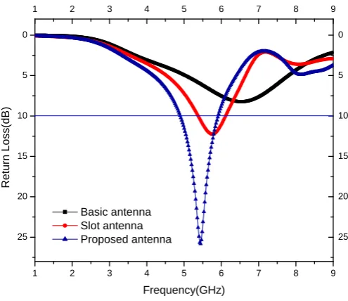
The evolution process of the compact Trapezoid shape patch antenna is depicted in Fig.2, for achieving the desired WLAN frequency band. For achieving the best antenna design, we perform the analysis and optimization of several antenna parameters in the structure. In first antenna evolution the compact trapezoid shape patch antenna consist of a trapezoidal radiating patch called as basic antenna resonates at 6.5 GHz frequency with a return loss of 8.22 dB. In the second evolution step two rectangular slots are introduced in the basic antenna to form E shape which is called slot antenna and radiates at 5.7 GHz with a return loss of 12.25 dB. In the final evolution step two trapezoidal slots are introduced in the slot antenna and called as proposed antenna. The proposed antenna resonates at 5.44 GHz frequency with 25 dB return loss.
[image:2.595.49.285.201.334.2]The return loss response of proposed antenna geometry for each evolution step is shown in Fig.3. The three antennas in the evolution process are named as basic antenna, slot antenna and proposed antenna.
Fig.3: Return loss of Antenna Evolution
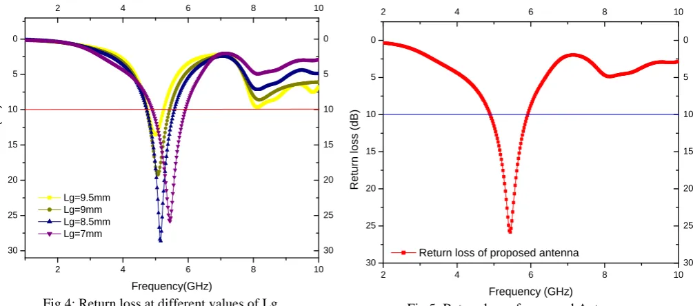
The Fig.4 depicts the optimized results of the proposed antenna.The effect of different values of Lg on the return loss of the antenna is shown in the return loss verses frequency graph. From the graph we concluded that at higher value of Lg the bandwidth and return loss of the antenna is less. As the length of ground plane is decreased the return loss and bandwidth both are improving. In this work our main goal is to improve the bandwidth of the antenna so we considered the Lg= 7mm in our proposed design because at this value we obtain a bandwidth of around 1GHz and also covers the frequency band of WLAN 5.2 GHz, 5.8 GHz..
1 2 3 4 5 6 7 8 9
25 20 15 10 5 0
1 2 3 4 5 6 7 8 9
25 20 15 10 5 0
R
e
tu
rn
L
o
ss(d
B)
Frequency(GHz) Basic antenna
[image:2.595.306.554.304.518.2]Fig.4: Return loss at different values of Lg.
For optimizing the antenna parameters to improve the performance of the antenna thedifferent parameters are optimized. In the table given below the effect of different values of length of ground Lg on the antenna bandwidth, return loss is listed which depicts the best results at 7mm .
Table2: Optimization of Trapezoid shape patch antenna.
Length of
ground(Lg)
Operating
Freq(GHz)
Return
Loss (dB)
Bandwidth
(GHz)
9.5 mm
4.9 GHz
13.5 dB
0.49 GHz
9 mm
5.06 GHz
19.2 dB
0.71 GHz
8.5mm
5.14 GHz
28.4 dB
0.83 GHz
7mm
5.44 GHz
25.8 dB
1.01 GHz
The simulated return loss of the proposed antenna is shown in Fig. 5. The proposed antenna design is simulated with the help of Zeland IE3D simulator and resonates at frequency of 5.44 GHz with a return loss of 25.8dB and an impedance bandwidth of around 1 GHz from 4.9 GHz to 5.9 GHz. The resonating bands provide a suitable bandwidth for the WLAN applications.
Fig.5: Return loss of proposed Antenna.
The current distribution in the proposed antenna design is shown in Fig. 6 at resonating frequency of 5.44 GHz. At this resonating frequency the maximum value of current obtained is 26.769 A/m. The different colors in the pattern represents the strength of current in different parts of antenna, the red color is for maximum current and blue is for minimum value of current.
Fig.6: Current Distribution of proposed antenna.
The normalized simulated 2D radiaton pattern on E-field and H- field for 5.44 GHz frequency is shown in Fig. 7. The E- field radiations are bidirectional in nature and H- field radiations are omni-directaional in nature for the antenna at 5.44 GHz resonating frequency as shown in the plot below.
2 4 6 8 10
30 25 20 15 10 5 0
2 4 6 8 10
30 25 20 15 10 5 0
R
e
tu
rn
L
o
ss(d
B)
Frequency(GHz) Lg=9.5mm
Lg=9mm Lg=8.5mm Lg=7mm
2 4 6 8 10
30 25 20 15 10 5 0
2 4 6 8 10
30 25 20 15 10 5 0
R
e
tu
rn
l
o
ss
(d
B)
Fig.7 (a): E-field of antenna radiation pattern at 5.44 GHz.
Fig.7 (b): H- field of antenna radiation pattern at 5.44 GHz.
It is clear fron the E-plane and H-plane that the radiations are in semi directional pattern of E and H fields. The radiation pattern depicts that the given antenna can radiate and receive in almost every direction with fair radiation characteristics.
[image:4.595.318.547.50.276.2]The gain verses frequency plot of the proposed antenna is shown in Fig. 8 which shows that at a frequency of 4-6 GHz gain of around 1.5dB is ahieved for the antenna. The given antenna geometry works satisfactorily for WLAN application with better impedance bandwidth and gain.
Fig. 8: Gain of proposed antenna.
IV. CONCLUSION
A compact CPW-fed Trapezoid Shape antenna for WLAN Application is examined to operate at frequency 4.9GHz to 5.91 GHz with good bandwidth and small size. The proposed antenna design resonates at 5.44 GHz with a return loss of 25.8 dB and bandwidth of 1GHz covers both 5.2 GHz and 5.8 GHz frequency of WLAN. The 2D radiation pattern is observed as bidirectional in E-field and omni-directional in H-field. The parametric study helps in obtaining the best optimized antenna parameters for enhancement in antenna performance. The proposed antenna geometryhascompact size, cheaper in cost. The antenna is suitable for WLAN Application with one resonant band and better impedance bandwidth.
REFERENCES
1. K. R. Carver and J. W. Mink, “Microstrip Antenna Technology,” IEEE Trans. Antennas Propag., vol. 29, no. 1, 1981, pp. 2–24.
2. N. Prema and A. Kumar, “Design of multiband microstrip patch antenna for C and X band,” Optik
(Stuttg)., vol. 127, no. 20, 2016, pp. 8812–8818.
3. S. Bisht, S. Saini, V. Prakash, and B. Nautiyal, “Study The Various Feeding Techniques of Microstrip Antenna Using Design and Simulation Using CST Microwave Studio,” Int. J. Emerg.
Technol. Adv. Eng., vol. 4, no. 9, 2014, pp. 318–324.
4. R. K. Raj, M. Joseph, C. K. Aanandan, K. Vasudevan, and P. Mohanan, “A new compact microstrip-fed dual-band coplanar antenna for WLAN applications,” IEEE Trans. Antennas
Propag., vol. 54, no. 12, 2006, pp. 3755–3762.
5. R. Vivek and S. Sreenath, “Coplanar Waveguide ( CPW ) -Fed Compact Dual Band Antenna for 2 . 5 /
5 . 7 GHz
[image:4.595.58.287.76.299.2] [image:4.595.72.268.375.597.2]6. A. Dastranj and H. Abiri, “Bandwidth enhancement of printed E-shaped slot antennas fed by CPW and microstrip line,” IEEE Trans. Antennas Propag., vol. 58, no. 4, 2010, pp. 1402–1407.
7. C.-S. Eun, J.-W. Kim, T.-H. Jung, H.-K. Ryu, J.-M. Woo, and D.-K. Lee, “Compact Multiband Microstrip Antenna Using Inverted-L- and T-Shaped Parasitic Elements,” IEEE Antennas
Wirel. Propag. Lett., vol. 12, pp. 1299–1302, 2013.
8. I. Wire and W. Communications, “Small Planar Monopole Antenna With a Shorted Parasitic,” vol. 52, no. 7, 2004, pp. 1903–1905.
9. L. Dang, Z. Y. Lei, Y. J. Xie, G. L. Ning, and J. Fan, “A compact microstrip slot triple-band antenna for WLAN/WiMAX applications,” IEEE Antennas
Wirel. Propag. Lett., vol. 9, 2010, pp. 1178–1181.
10. K. Srivastava, A. Kumar, B. K. Kanaujia, S. Dwari, and S. Kumar, “Multiband integrated wideband antenna for bluetooth/WLAN applications,” AEU -
Int. J. Electron. Commun., vol. 89, no. January,
2018, pp. 77–84.
11. S. S. Al-Bawri, M. F. Jamlos, P. J. Soh, S. A. Aljunid Syed Junid, M. A. Jamlos, and A. Narbudowicz, “Multiband slot-loaded dipole antenna for WLAN and LTE-A applications,” IET
Microwaves, Antennas Propag., vol. 12, no. 1,
2017, pp. 63–68.
AUTHORSPROFILE
Poojareceived her B.tech degree in Electronics & Communication Engineering from A.B.V.G.I.E.T., Pragatinagar, Shimla,H.P., India in 2017. She is currently a M.E. student at Chandigarh University, Punjab, India in the department of Electronics & Communication since 2017..
DavinderParkashreceived his B.Tech&M.Tech degree from the department of Electronics & Communication Engineering fromKurukshetrs University and NIT Kurukshetra, India. He completed his PHD degree from Thapar University, Patiala.