International Journal of Innovative Technology and Exploring Engineering (IJITEE) ISSN: 2278-3075, Volume-8 Issue-7, May, 2019
Abstract-This paper design and evaluate the DC to DC boost converter for speed control of brushless direct current electric motor (BLDCM) using variable direct current (DC) voltage, which is carrying out in discontinuous conduction mode (DICM) by adaptive neuro fuzzy interference system (ANFIS) controller for improving the power quality issues such as obtaining the unity power factor at AC mains along with reduction of THD (total harmonic distortion). The newly designed converter is simulated and verified in Matlab/simulink environment. The obtained simulation output is matched by hardware result by developing a proposed converter in prototype model.
Index Terms: BLDC electric motor, Boost-DICM converter and Adaptive neuro fuzzy interference system.
I.INTRODUCTION
Commonly for stumpy power application prefers the BLDC electric motor compared to other types motors like induction motor and synchronous reluctance motor due to their maximum efficiency with excellent performance, need little maintenance, high uniform flux density, smallest problem of electromagnetic interference. BLDC electric motor is not only used for low and medium power application such as blowers, fans, washing machines, etc. it is also recommended for functioning the high power applications such as hybrid electric vehicle, air conditioning devices (HVAC), lots of industrial tool and biomedical equipments [1]-[4].
Usually these motors have three phase concentrated windings on stator and permanent magnets on rotor. BLDC electric motor is also called as electronically commutated electric motor. In this motor, electronic commutation is operated instead of mechanical commutator in conventional motors, which depends upon the rotor position sensor (Hall Effect sensor) embedded in the rotor. Since there is no problem of wear and tear of brushes also less possible of sparking in BLDC electric motor. Power factor correction problem and total harmonic distortion are the major disquiet in development of stumpy and average application targeting home appliance [5]-[6].
Revised Manuscript Received on May 10, 2019
S. Swapna, Research Scholar , Department of Electrical and Electronics Engineering,/Vel Tech Rangarajan Dr. Sangunthala R&D Institute of Science & Technology, Chennai, Tamil Nadu, India .
K.Siddappa Naidu, Professor, Department of Electronics and Communication Engineering / Vel Tech Rangarajan Dr. Sangunthala R&D
A single step PFCC is preferred as an alternative of two step converters due to handling of fewer components for truthful
control of direct current link voltage also getting power factor as nearby unity value. In olden methods, motor speed control with constant DC link voltage is used by PWM-VSI, which leads enhancing the switching losses in electronic commutator due to this reason increase the switching frequency in voltage source inverter. The above trouble can be overcome by getting the variable DC link voltage because speed control of brush less DC electric motor is proportional to DC link voltage, which offers less switching losses [7]-[8]. Conventional methods gives poor power factor correction such as less than 0.8 and THD has 65% due to non-sinusoidal current at AC mains when BLDC electric motor fed from diode bridge rectifier. There are two modes of operation available based on conduction for PFC converter such as continuous mode and discontinuous mode. Basically the choice of modes depends upon the low, medium and high power application because these modes of operation affect increases cost of operation and number of components used in PFC converter [9]-[10].
Voltage across DC link capacitor and DC link current flowing in inductor are continuous for CCM. It is not cost effective solution because two voltage sensors are need for sensing the both supply voltage and DC link output voltage, which increases number of usage voltage sensors. Whereas in discontinuous mode (DCM), Single voltage sensor is adequate for observe the DC link voltage instead of two voltage sensor (CCM) for obtain the effective PFC converter at AC main supply for low power application [10]-[13].
This article gives the variable direct current (DC) link voltage of voltage source inverter all the way through boost-DICM converter, which is controlled by adaptive neuro fuzzy interference system controller instead of conventional controller (PI and PID controller) for improving power factor correction with less usage of apparatus.
II. PROPOSEDPFCBOOST-DICMCONVERTER
FEDBLDCM
Characteristic Analysis of PFC using DC-DC
Boost Converter Fed BLDCM
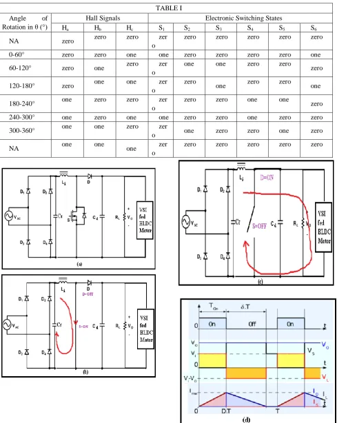
Fig.1 PFC Boost-DCM converter fed BLDC Electric Motor
From figure 1, to convert AC in to DC we used DBR, here voltage (Vs) supplied as input through source impedance Zs. Generally low pass LC filter is utilized to resolve the harmonics present at AC main in the output of diode bridge rectifier (DBR). Obviously it occupies more space, to reduce that we implemented C filter instead of LC filter. Here main switch (S), inductor (L), diode (D), capacitor (Cd) and resistor (R) are designed in such a way that to convert low level voltage into desired level. In real time it is not possible to maintain the constant rpm in BLDC motor. To compare the reference speed and actual, generally we used speed comparator.
Actual speed is sensed by hall-effect sensor which will get from rotor, the corresponding voltage Vdc is arrived from the DC to DC power boost converter. We set some value as reference speed, voltage reference generator will generate proportional voltage signal Vdc* from the given input reference speed. To control the power factor in general PI controller and PID controller are used. Here our main goal is to attain power factor as unity, to achieve that we build power factor correction block with voltage comparator, reference current generator, pulse width modulation current controller, we newly implemented ANFIS controller.
III. OPERATINGPRINCIPLEOFPROPOSEDPFC
BOOSTCONVERTER
Boost converter parts are designed based on desired output voltage for low power application with the parameters input
International Journal of Innovative Technology and Exploring Engineering (IJITEE) ISSN: 2278-3075, Volume-8 Issue-7, May, 2019
to decayed through diode ‘D’ and capacitor ‘Cd’ until inductor current fully discharged through BLDC electric motor (Discontinuous Mode) as shown in figure 2 (c).
[image:3.595.57.547.106.720.2]Fig. 2. Operation of proposed PFC converter (a)-(c) for TABLE I
Angle of
Rotation in θ (°)
Hall Signals Electronic Switching States
Ha Hb Hc S1 S2 S3 S4 S5 S6
NA zero zero zero zer
o
zero zero zero zero zero
0-60° zero zero one one zero zero zero zero one
60-120° zero one zero zer
o
one one zero zero
zero
120-180° zero one one zer
o
zero
one zero zero one
180-240° one zero zero zer
o
zero zero one one
zero
240-300° one zero one one zero zero one zero zero
300-360° one one zero zer
o one zero zero one zero
NA one one one zer
o
positive half cycle at AC mains and (d) along with waveforms. (a) DICM Boost converter (b) DICM Mode I (c) DICM Mode II (d) Waveforms of completer duty cycle in discontinuous mode
IV. CONTROL OF BLDC ELECTRIC MOTOR
(ELECTRONICCOMMUTATION)
[image:4.595.314.546.52.151.2]BLDC electric motor speed can be controlled by VSI based on the rotor position sensors (RPS) such as Hall Effect sensors, which is embedded in rotor. Motor consists of three phases (a, b & c) on stator, which is symmetrically displaced by 120° displacement at the centre of each phase. At every 60° time interval any two phases (a & b) are energized by turn on the two switches S1 and S4 as shown in figure 3. From DC link capacitor line current iab flowing through DC link voltage, self inductance La & Lb, mutual inductance M, back electromotive forces ean & ebn of the stator windings. Table I clearly says that switching conduction states of electronic commutator (VSI) speed control of electric motor based on the RPS, such as Hall Effect sensors.
Fig. 3. Conduction of S1 and S2 fed BLDC motor
V. DESIGNOFPFCBOOSTCONVERTER IN DCM
To design and working in DCM of step up or boost converter with the help of ANFIS controller such as discontinuous flow of inductor current (iL) in a switching time for non linear speed control of BLDCM. Here we design a output power of converter is 250 watts since our rating of BLDC electric motor power is 251 watts, the complete detail specification with rating of BLDCM is tabulated in table-2.
The following equations (1) & (2) designed for the average input voltage and voltage conversion ratio is given as [24]
The newly implemented ANFIS control converter is designed for dc link voltage range between Vdmin=50 volts to Vdmax=150 volts with Vdc(desi)=100 volts(nominal value). Moreover we can easily find out the duty cycle value from minimum to maximum respective of Vdmin=50 volts to Vdmax=150 volts is represented as dmin to dmax.
Similarly,
Let we design the overall duty cycle (D) of proposed converter with ANFIS control, Where n is the overall efficiency of converter (n=100%) and output current (Io) is given as,
For calculate the input ripple current (ΔIL) of newly implemented converter by following equation is written as,
Generally, inductor ripple current is 20% to 40% of the output current (Io) for excellent evaluation in DC to DC power converter which is operated in DCM. Let us assume here 40% as ripple output current.
A. Design of DC Inductor in DCM (Li in Henry):
The exact valuation of DC inductor is designed in boost converter with ANFIS controller when it is functioning in critical conduction mode (DCM) is given as,
Where Vdcmin is the minimum input voltage in volts, Vdcmax is the maximum input voltage in volts and fs is the switching frequency in Hertz ( fs=20KHz).
B. Design of DC Capacitor in DCM (Cd in Farad):
International Journal of Innovative Technology and Exploring Engineering (IJITEE) ISSN: 2278-3075, Volume-8 Issue-7, May, 2019
Where next term corresponds to DC link capacitor is written as,
Let we find out the DC link ripple voltage with respect to ic(t) is given as [22],
Sin(ωt)=1 when finding the maximum voltage ripple at DC link capacitor is,
For allowable ripple content in ΔVdc is considered as 3% of Vdc(desi) as,
Hence, nearest possible value of Cd is choose as 1500µF
C. Design of input Capacitor filter in DCM (C in Farad): To abolish the harmonic content which is present in the input side of AC by a designing capacitor (Cf) filter in planned converter with adaptive nuero fuzzy interference controller.
VI. CONTROL OF PFC BOOST-DICM
CONVERTER-VSIFEDBLDCELECTRICMOTOR
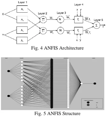
[image:5.595.313.532.48.289.2]From the ANFIS structure appeared in Figure 4 & 5, it has been seen that when the estimations of the reason parameters are fixed, the by and large yield can be communicated as a direct mix of the subsequent parameters. Hybrid learning calculation is a mix of both back proliferation and the least square calculations. Hybrid learning algorithm Comprises of two passes, to be specific forward pass and in reverse pass. In the forward go of the half and backward pass calculation, useful signs go ahead up to layer 4 and the ensuing parameters are distinguished by the least squares gauge. The back spread is utilized to distinguish the nonlinear parameters (premise parameters) and the least square is utilized for the straight parameters in the ensuing parts.
[image:5.595.327.534.428.647.2]Fig. 4 ANFIS Architecture
Fig. 5 ANFIS Structure
For the proposed framework, the information and yield enrollment capacities are appeared in Fig.6. The most normal state of enrollment capacities is triangular, albeit trapezoidal and ringer bends are likewise utilized, yet the shape is commonly less vital than the quantity of bends furthermore, their position. Participation capacities are characterized inside the standardized range and connected with each mark: NB (negative enormous), NS (negative little), ZO (zero), PS (positive little), and PB (positive enormous). Five enrollment capacities are picked for blunder (e), change in mistake (de) and for yield (u).
Fig.6. Membership Functions
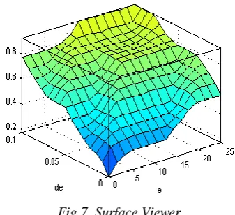
[image:5.595.53.287.478.589.2]Fig.7. Surface Viewer
The ANFIS-PID control of the front-end boost converter creates the pulse width modulation pulses for switches ‘S’ for getting the good control of direct current link voltage with power factor correction activity at AC mains. Here single voltage approach is used for the PFC DC-DC boost-DICM converter working in discontinues conduction mode. A reference dc connect voltage (Vdc*) is generated as
Where the motor voltage consistent (kv) and the reference speed (ω∗), individually. The voltage error signal (Ve) is created by looking at the reference direct current (DC) connect voltage (V *dc) with the detected direct current (DC) interface voltage (Vdc) as
Where k speaks to the kth examining moment in controller. Where Ve is given to the voltage ANFIS-PID controller to create a controlled yield voltage (Vcc) as
Where kp and ki are the corresponding gain of proportional integral gain controller. The output of ANFIS-PID controller is given to PWM pulse as
Where Sw correspond to switch of the boost converter. The specification of BLDC motor rating and design parameters of Boost converter is shown in table II & III respectively.
Table II
BLDC MOTOR RATING
Number of poles (p) 4
Prated (Rated power) 251.32 Watta
Vrated (Rated dc link
voltage)
200 Volts
Trated (Rated torque) 1.2 Newton-metre
ωrated (Rotor speed) 2000 revolution per
minute
Kt (Torque constant) 1.05 Newton-metre per Ampere
resistance)
Lph (Phase
inductance)
25.71 milli-Hentry
J (Moment of inertia) 1.3 ×10⁻⁴
Newton-metre per
[image:6.595.88.257.57.211.2]Ampere2
TABLE III - DESIGN PARAMETERS OF BOOST CONVERTER
Parameters Simulation Parameters
Vin 198V
dmin 0.2016
dmax 0.4310
Cf 0.2nF
Li 1000µH
Cd 1500µF
VII. SIMULATIONOFPROPOSED BOOST-DICM
FEDBLDCELECTRICMOTOR
The characteristics of proposed boost-DICM BLDC electric motor fed voltage source inverter are simulated in MATLAB/simulink environment using sim power system tool. The motor speed is controlled by electronic commutator in voltage source inverter, which gets input from our designed DC to DC boost converter in DICM. Here, the neural network concept adaptive neural fuzzy interference system controller monitors the switching frequency of MOSFET switch ‘S’. By implementation of ANFIS, we achieved problem faced in power quality such as less in THD value and inability to maintain unity in power factor AC mains.
The parameters THD level and power factor involved in BLDC motor are controlled and the characteristics obtained such as supply voltage (V) in volts, supply current (I) in amps, stator EMF, rotor speed (N) in rpm ,motor torque (T) in Nm , inductor current (iL) in amps and inductor voltage (VL) in volts are shown in the following graph in 4.
[image:6.595.42.272.628.787.2]International Journal of Innovative Technology and Exploring Engineering (IJITEE) ISSN: 2278-3075, Volume-8 Issue-7, May, 2019
Fig.4. Steady-state characteristic of the proposed PFC-DICM fed BLDC electric motor.
[image:7.595.315.549.435.716.2]An introducing adaptive neuro fuzzy system controller for getting power factor as nearby unity value in power factor correction boost converter is execution in discontinuous conduction mode. This converter is designed and analyzed by varying the direct current link voltage between the range as 50 volts to 150 volts, corresponding parameters such as speed, THD value and power factor is measured using MATLAB simulink environment tool. From table IV clearly says that, if varying the direct current (DC) link output voltage of PFC converter in DICM using ANFIS controller for speed control brushless electric motor fed VSI, will obtain the power factor value as unity and less amount harmonic distortion.
TABLE IV
PERFORMANCE OF BOOST CONVERTER (DICM) UNDER VARIOUS DC LINK VOLTAGES
DC Voltage(V)
Speed
(rpm) THD(%)
Pow er Factor
50 165 11.4 0.99
49
60 216 9.46 0.99
72
70 240 8.36 0.99
81
80 310 7.12 0.99
86
90 370 6.51 0.99
9
100 410 6.08 0.99
93
110 440 5.69 0.99
95
120 500 5.39 0.99
97
130 550 5.00 0.99
98
140 590 4.42 1
150 630 4.31 1
VIII.COMPARISON ON VALUES OF HARMONIC
DISTORTION AND POWER FACTOR IN DICM
Table-V clearly says that, comparative analysis of proposed configuration of PFC converter (boost-DICM) with conventional converters. Here our proposed boost-DICM converter having minimum THD value such as less than 4.5% as shown in figure 5 in that, power factor value as one when we applying above 140 volts. The above results proved that our proposed converter is performed well for power quality issues compared to other type of converters.
[image:7.595.49.289.681.788.2]IX. HARDWAREVALIDATIONOFPROPOSED
BOOST-DICMCONVERTER
DSP kit based on TI-TMS320F2812 is utilized for the improvement of PFC in newly implemented DC-DC converter fed BLDC electric motor drive in DICM. Opto coupler 6N136 circuit is utilized for isolation between gate driver switches of voltage source inverter and Digital signal processor. Rotor position sensor is also utilized which is embedded on rotor for sensing the exact position of rotor on motor by using Hall-effect position signals.
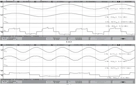
[image:8.595.57.528.175.469.2]The steady-state characteristic and analysis of the proposed Brushless DC drive indicating supply voltage (Vs), supply current (Is), DC link voltage (Vdc), and stator current (Ia) for the dc interface voltages of 50 Volts and Variation of inductor's flows (iLi) and with input voltage and current individually as exposed in figures 6 & 7. PFC can be achieved unity at AC main by reducing THD level using proposed design of new DC-DC boost converter.
Fig. 6. Characteristics of supply voltage (Vs) , Supply Current (is), DC link Voltage (Vdc) and Stator current (is) for newly
implemented Boost-DICM converter (a) 200 V and (b) 50 V
TABLE V
COMPARATIVE ANALYSIS OF PROPOSED CONFIGURATION WITH CONVENTIONAL SCHEMES
Parameters
DBR with C
Filter
Conventional PFC Boost
Converter
PFC Cuk Converter
PFC Luo Converter
Proposed Boost-DCIM Converter
THD (%) 228.66 45.05 60.81 20.4 4.31
[image:8.595.81.518.526.684.2]International Journal of Innovative Technology and Exploring Engineering (IJITEE) ISSN: 2278-3075, Volume-8 Issue-7, May, 2019
Fig. 7. Deviation of inductor’s currents (iLi) and with supply voltage (Vs) and supply current (is).
A.Comparison is based on Power Quality issues using
PFC Boost-DICM Converter
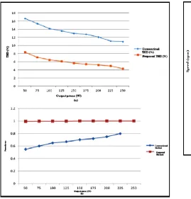
The evaluation statement arrived for old and newly implemented system based on the above graph 6.3 (a), THD value arrived 12 in conventional and in proposed (new implemented) system it is less than 4. From this, it is clear that, supply side power factor improved by reducing the THD margin with increase in output power. The power factor is maintained constant such as nearby unity in the newly implemented system with the help of adaptive neuro fuzzy interference system controller in DC to DC power factor boost converter. But, in the case of conventional schemes, it is less than 0.8 in PFC converter as shown in figure 8 (b).
Fig.8 (a & b) Comparative analysis of power factor variation with output power for the conventional and the
Proposed Boost converter.
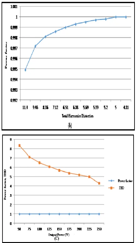
From graph 9 (a) it is clear that, we got the uniform improvement in speed with increasing input supply voltage by maintaining power factor as unity as well as reduction in THD level. We expect pure sine wave as input for that ANFIS controller is implemented. With the help of DBR, the pure sine wave is converted into Dc (50 volts). The obtained 200 volts is improved into 24 volts by introducing DC to DC boost converter. From the graph 9 (b) it is clear that, total harmonic value is reduced progressively with the enhanced by direct current (DC) link voltage. Also, the plot 9 (c) shows the improvement in output voltage obtained with gradual reduction by total harmonic distortion with constant power factor.
[image:9.595.58.328.451.732.2]Fig. 9. Comparison of (a) Speed vs supply voltage (b) Power factor vs THD and (c) Power factor, THD vs Output
Power using PFC converter Fed BLDC electric drive.
X.CONCLUSION
A new boost converter based voltage source inverter fed BLDCM has been planned for minimum power applications with PFC. Power electronic switching losses in VSI can be minimized by changing the voltage at DC link using newly designed converter (Boost-DICM) for the electronic commutation of the motor. The DC to DC power boost converter has been worked in discontinuous mode for accomplishing an innate PFC at input side. A sensible exhibition has been acknowledged for speed control of BLDC drive and supply voltage variety with power quality indices inside the worthy furthest reaches of IEC range 61000-3-2. To finish with, an exploratory model of the proposed Boost converter BLDC engine drive has been created to fulfill the execution of the proposed BLDC drive under speed control with improved power quality issues at supply mains for low power applications.
REFERENCES
1. J. S. Mayer and O. Wasynczuk, “Analysis and modeling of a single phase brushless dc motor drive system,” IEEE Trans. Energy Convers., vol. 4, no. 3, pp. 473–479, Sep. 1989.
2. C. Cossar, L. Kelly, T. J. E. Miller, C. Whitley, C. Maxwell, and D. Moorhouse, “The design of a switched reluctance drive for aircraft flight control surface actuation,” in Proc. IEE Colloq. Elect. Mach. Syst. More Elect. Aircraft, 1999, pp. 2/1–2/8.
3. R. Krishnan, D. Blanding, A. Bhanot, A.M. Staley, and N. S. Lobo, “High reliability SRM drive system for aerospace applications,” in Conf. Rec. IEEE IECON, 2003, vol. 2, pp. 1110–1115.
4. A. G. Jack, B. C. Mecrow, and J. A. Haylock, “A comparative study of permanent magnet and switched reluctance motors for high-performance fault-tolerant applications,” IEEE Trans. Ind. Appl., vol. 32, no. 4, pp. 889–895, Jul./Aug. 1996.
5. P. Pillay and R. Krishnan, “Application characteristics of permanent magnet synchronous and brushless dc motors for servo drives,” IEEE Trans. Ind. Appl., vol. 27, no. 5, pp. 986–996, Sep./Oct. 1991. 6. D. Hanselman, Brushless Permanent Magnet Motor Design, 2nd ed.
Cranston, RI: The Writers’ Collect., 2003.
7. B. Singh, B. N. Singh, A. Chandra, K. Al-Haddad, A. Pandey, and D. P. Kothari, “A review of single-phase improved power quality ac dc converters,” IEEE Trans. Ind. Electron., vol. 50, no. 5, pp. 962–981, Oct. 2003.
8. B. Singh, S. Singh, A. Chandra, and K. Al-Haddad, “Comprehensive study of single-phase ac-dc power factor corrected converters with high-frequency isolation,” IEEE Trans. Ind. Informat., vol. 7, no. 4, pp. 540–556, Nov. 2011.
9. Vashist Bist, Bhim Singh. "An Adjustable-Speed PFC Bridgeless Buck–Boost Converter-Fed BLDC Motor Drive", IEEE Transactions on Industrial Electronics, 2014
10. N. Mohan, T. M. Undeland, and W. P. Robbins, Power Electronics: Converters, Applications and Design. Hoboken, NJ, USA: Wiley, 2003. 11. A. Emadi, A. Khaligh, Z. Nie, and Y. J. Lee, Integrated Power Electronic
Converters and Digital Control. Boca Raton, FL, USA: CRC Press, 2009. 12. Sanjeev Singh and Bhim Singh., "Voltage Controlled PFC SEPIC Converter fed PMBLDCM Drive for an Air-Conditioner," Power Electronics, Drives and Energy Systems (PEDES) & 2010 Power India, 2010 Joint International Conference, pp. 1-6, Dec. 2010.