Design and Development of a Small-Scale Pellet Extrusion
System for 3D Printing Biopolymer Materials and Composites
by
Sean Matthew Whyman
Submitted to the School of Engineering and Advanced Technology
in partial fulfillment of the requirements for the degree of
Master of Engineering
Mechatronics
at
Massey University, Auckland
Feb 2018
Author . . . .
School of Engineering and Advanced Technology
Feb 28, 2018
Design and Development of a Small-Scale Pellet Extrusion System for 3D
Printing Biopolymer Materials and Composites
by
Sean Matthew Whyman
Submitted to the School of Engineering and Advanced Technology
on Feb 28, 2018, in partial fulfillment of the requirements for the degree of
Master of Engineering
Abstract
The aim of this research project is to develop a pellet-based 3D printing system that will accept
biopolymer pellets to experiment with composite additives. Currently a majority of easily
accessi-ble or hobbyist 3D printers use filament as the input material for extrusion. With the goal in mind
of printing using biopolymer materials and additive mixes, using filament remains achievable, but it would not provide as much freedom and exploration into unexplored areas. This can be an issue
on the research side and a restriction on the hobbyist or consumer side where the material variety
and printing capabilities such as recycling are much harder to achieve if not out of reach.
This research report presents the process of designing and developing a pellet-based extrusion
system to accept a range of biopolymer pellets for 3D printing. The system has been designed from
first principles and therefore can be extended to other materials with slight parameter adjustments
or hardware modifications. A robust mechatronic design has been developed using an
uncon-ventional yet simplistic approach to achieve the desired operating characteristics. The extrusion
system uses a series of control factors to generate a consistent output of material over the course of a print. The platform and surrounding processes are setup so that software can be used to define
the printing parameters, thus allowing for easy and simple adaption to dissimilar materials. The
utility of the extruder is demonstrated through extensive printing and testing of the printed parts.
Using Polylactic Acid (PLA) as the base material to test and develop the extruder system, the
results of the print quality evolved as the extruders design became more robust. Several factors of
the extruder contributed to large improvements such as; the hoppers rigidity, the internal
geome-tries, the cooling efficiency and the software parameters. As these features progressed it enabled a
much finer print quality and dimensional accuracy similar to what is seen in current Fused
Depo-sition Modelling (FDM) extruders today. The print comparison tests were carried out against FDM
PLA samples to reveal a high similarity in mechanical strength and improvements to some areas of
surface quality. Further testing revealed success in testing other materials such as PETG, as well as
successfully mixing and extruding Harakeke flax fiber composite additives.
The major limiting factor of the current design is its ability to withstand heat propagation up
through the extrusion system. As higher temperatures are required to melt different polymers, the
thermal tolerance of the drive motor will quickly reduce causing inconsistencies earlier on during
printing. The water cooling block added into the design only prevent heat from travelling through the wall of the extruder and not the screw. A further limitation is that the extruder is made using
aluminium as the material. This allows for quick start-up times, but it also wears at a fast rate and
the shaved off aluminium ends up contaminating the processed material.
Because this extruder accepts pellets, the range of possibilities for future applications is vast.
With further improvements to better refine the process, the material range could expand to more
unconventional materials that otherwise could not be printed using popular extrusion methods. As
for a business sense, there are few well known methods of pellet printing and especially affordable
systems. Therefore, an opportunity could be present to develop a commercially affordable desktop
system or spin-off to enter a niche market.
Acknowledgments
I am grateful for having such a supportive family to which I can rely on in times of need. To my
Mother Claire and sibling Brooke, for providing an emotional pillow to help even out the bumpy
road and soften any tumbles that occur along the way. To my Father Lee for starting me off on my
journey and providing the barriers to my path, keeping me from going astray. He has given me the tools to get me to where I want to be, and for that I cannot thank him enough. I am also grateful to
all my other family members and friends who have supported me along the way.
A great thank you to A/Prof. Johan Potgieter for not only being my supervisor, but for taking
the time to sort out issues, finding the financial support for my Master’s degree and being behind
the scenes throughout my entire university degree. A special thank you to Dr. Khalid Arif, for
pro-viding long term guidance through undergraduate mentorship and in postgraduate supervision.
He is always there to offer his thoughts, providing both focus and encouragement. But more than
that, He applies himself to become personally involved with projects and students, thus offering a
more structured growth, both personally and professionally. For this I thank him. Further thanks go to Dr. Frazer Noble and all the other staff members in the school of engineering that have poured
effort into my university journey.
This research was part of the Extrusion Plus program led by Scion New Zealand, and funded
by the Ministry of Business, Innovation, and Employment (MBIE) funding under High Value
Man-ufacturing and Services (HVMS) Enabling Technologies investment contract. A special thanks to
Dr. Marie-Joo Le Guen for providing the materials and related expertise.
A special mention to a close group of friends, Andrew Kvalsvig, Cameron Mearns, Dion
Mans-field and Hayden Wilson who have stuck by one another from the beginning, through thick and
thin, both in and around the workplace. I also appreciate the company of Arno Ferreira, Tim Sut-cliffe, Mitchell Hampton and Blair Dixon for providing a stress relief and comedic encouragement
around the workplace. I am grateful to Tatiana Daysh for the support and assistance offered, as
well as the general company to help balance out the everyday chaos that sometimes occurs.
Without this collective group of people, I would not have ventured this far, I thank you all for
the encouragement and look forward to the future.
Contents
1 Introduction 1
2 Literature Review 4
2.1 Types of Additive Manufacturing . . . 4
2.1.1 Material Extrusion . . . 7
2.1.2 VAT Photopolymerisation . . . 8
2.1.3 Powder Bed Fusion . . . 10
2.1.4 Direct Energy Deposition . . . 11
2.1.5 Sheet Lamination . . . 12
2.1.6 Material Jetting . . . 13
2.2 Extrusion Printing Materials . . . 14
2.2.1 Common Extrusion Materials . . . 14
2.2.2 Extrusion of Biopolymer and Composite Materials . . . 14
2.2.3 Recycling of Material . . . 18
2.3 Current State of Extruder Technology . . . 20
2.3.1 Deposit Extruder Types . . . 21
2.3.2 Screw Extrusion . . . 24
2.3.3 FDM Platform Designs . . . 31
2.4 Summary of Findings . . . 33
3.2 Extruder System Design . . . 37
3.2.1 Material and Extrusion Type . . . 39
3.2.2 Hopper Design . . . 40
3.2.3 Proposed Extruder Design . . . 42
4 Development of Printer Systems 49 4.1 Extruder Platform Development . . . 49
4.2 Extruder Design Process . . . 52
4.2.1 Hopper Development . . . 52
4.2.2 Cooling System Development . . . 59
4.2.3 Barrel, Screw and Die Development . . . 65
4.3 Measurement, Communication and Control . . . 70
4.4 Limitations and Improvements . . . 80
5 Mechanical Characterisation and Optimisation 81 5.1 Print Consistency and Calibration . . . 81
5.2 Part Preparation . . . 91
5.3 Speed Versus Temperature . . . 94
5.4 Nozzle Sizes . . . 95
6 Results 97 6.1 Printing Results . . . 97
6.2 Tensile Testing . . . 104
6.3 Recycling . . . 106
6.4 SEM Analysis . . . 108
7 Discussion and Conclusion 112 8 Future Recommendations 114
A Thermal Images 120
List of Figures
2-1 Melt extrusion additive manufacturing (FDM/FFF) [53] . . . 8
2-2 Stereolithography (SLA) additive manufacturing [39] . . . 9
2-3 (a) Inkjet powder bed printing (3DP), (b) Slective laser sintering (SLS) [39] . . . 10
2-4 Laser operated DED process [34] . . . 11
2-5 Sheet lamination additive process [36] . . . 12
2-6 Material jetting process [35] . . . 13
2-7 The Mark One 3D printer by MarkForged . . . 17
2-8 Different extruder types; (a) Filament extrusion, (b) Syringe extrusion, (c) Screw ex-trusion [62] . . . 20
2-9 Filament extrusion problems; (a) Filament is too thick, (b) Filament is too thin, (c) Filament buckling caused through the pressure being applied on the filament [62] . 22 2-10 Pellet extruder and positioning system [58] . . . 24
2-11 Common single stage continuous screw extrusion system [27] . . . 25
2-12 Single and twin screw extruders [55] . . . 26
2-13 Screw mixing type comparison [33] . . . 30
3-1 Pellet printing platform and extrusion system . . . 35
3-2 Image showing the relative size and shape of the PLA pellets used in testing and composite blends . . . 39
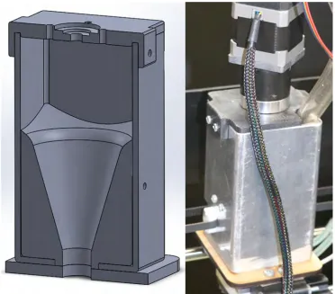
3-3 (Left) Assembled cross section view, (Rigth) Exploded cross section view . . . 40
3-4 Images showing the dripfeeder with motor attached and the seperate guidance tube 41 3-5 (a) Common single compression or three stage continuous extrusion screw [47], (b) rubber extrusion screw [57], (c) wood auger drill bit . . . 43
3-6 (a) Entire extruder system mounted in the printer, (b) full SolidWorks assembly of
the extruder . . . 44
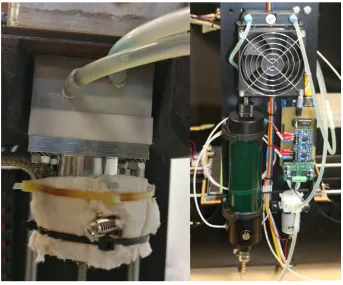
3-7 (Left) The Watlow 200W resistive heating band mounted at the extruders tip, (Right) Watlow PID single phase controller . . . 46
3-8 (Left) Coolant block around the neck of the extruder and the Teflon barrier, (Right)
radiator, coolant reservior, pump and control temperature/feed controller to complet
the loop . . . 47
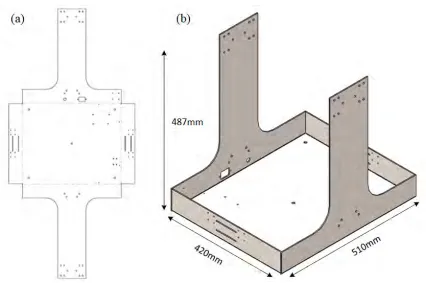
4-1 (a) Flat sheet metal view of the frame design, (b) Folded sheet metal view with scale
dimensions . . . 50
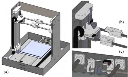
4-2 (a) Overview of the assembled model, (b) Close-up of the x/z axes custom joints and
sliders, (c) Custom mounts for the y axis . . . 51
4-3 Drip feeder good and poor design considerations [57] . . . 52
4-4 (Left) SLS printed original hopper design, (Right) Solidworks model of the original
hopper . . . 53
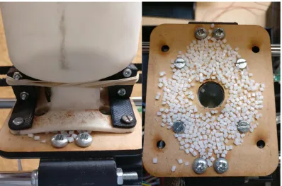
4-5 (Left) Flexing and deformation causes pellets to be force out, (Right) internal veiw of
escaped pellets . . . 53
4-6 (Left) Sectioned view of new design in SolidWorks, (Right) Application of new
hop-per design . . . 54
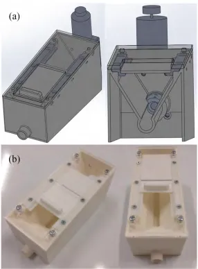
4-7 (a) SolidWorks assembly of initial feeder design, (b) SLS printed initial feeder design 56
4-8 SolidWorks model of the new feeder design . . . 57
4-9 (Left) Feeder mount on top of extruder motor, (Middle) feeder friction fits inside
mount, (Right) full feeder assembly with guidance tube into main hopper . . . 58
4-10 (a) Air cooled extruder with 40mm fan mounted, (b) SolidWorks model of the
air-cooled extruder . . . 59
4-11 (a) First water cooled channel design, (b) SolidWorks model of initial water-cooled
extruder . . . 60
4-12 Glycol based coolant temperature profile across several prints . . . 61
4-13 (a) Transient temperature study of the initial water-cooled block, stopped at 100∘C in 180 seconds, (b) a static temperature analysis of the initial water-cooled block . . . 62
4-14 (a) Transient temperature study of the new water-cooled block, stopped at 100∘C in
4-15 (a) PTFE thermal barrier water cooler, (b) SolidWorks model of the PTFE water
cooled design . . . 63
4-16 Water based coolant temperature profile across several prints . . . 64
4-17 Visual pressure comparison between a multi-zone continuous screw and the no com-pression auger screw [14] . . . 66
4-18 Screw geometries [57] . . . 67
4-19 (Top) Isolated melt region with correct feed transport, (Bottom) Block occurred mid way down . . . 68
4-20 (a) Initial air-cooled extruder design, (b) first water-cooled extruder design, (c) latest water-cooled extruder design with a thermal barrier . . . 69
4-21 Extruder system process . . . 71
4-22 Extruder sensor and monitoring locations . . . 72
4-23 Control interface for the temperature and feeder access . . . 74
4-24 (Left) Eagle designed controller schematic, (Middle) top view of controller contain-ing the interfaced electronics, (Right) underside of board showcontain-ing the deliberate jumper wires . . . 74
4-25 Main controller loop running based on a timer counting routine . . . 75
4-26 Serial reading function within the loop to detect incoming instructions . . . 76
4-27 Feeder speed function and drive motor encoder interrupt function . . . 77
4-28 Feeder enable/disable function and the feeders reverse function . . . 78
4-29 Temperature calculation function using an open source library . . . 79
5-1 First test print attempt carried out using a PLA and flax fiber blend . . . 82
5-2 (Left) Increments in layer thickness, (Right) Refined parameters . . . 82
5-3 (Top) Single layer test print for settings, (Bottom) Full print with adjusted parameters and skirt . . . 85
5-4 Continued testing from the early fiber blend to just PLA . . . 86
5-5 1.5mm aerated PLA extrudate . . . 86
5-6 (Left) High moisture content, (Middle) Insufficient material feed, (Right) Overheated material . . . 87
5-7 Test printed 40% infill part with collapsed bridging on top layer . . . 87
5-8 (Left) Stuttering drive motor caused oozing around the perimeter, (Right) Oozing
between movements across the part . . . 88
5-9 This is a set of g-code instructions written to extrude and wipe the nozzle before the print begins . . . 89
5-10 (Left) Excessive heat build-up caused runny viscosity, (Right) Insufficient layer cool-ing as the layer size reduced . . . 89
5-11 (Left) - (Middle) Visible build-up and mixing of aluminium contamination, (Right) Unmixed aluminium powder caused through rubbing . . . 90
5-12 Visual representation of the slicing operation carried out in Slic3r . . . 91
5-13 Pronterface as the graphical interface for the printer . . . 92
5-14 Basic considerations of die design [57] . . . 96
5-15 The different sizes and types of extrusion tips used (2.0, 1.5, 1.2, 1.0, 0.8, 0.6mm) . . . 96
6-1 Air-cooled extruder progress from the first print through to a more optimised result 98 6-2 (Top) Glycol-cooled extruder trialling parameters, (Bottom) More refined print settings 99 6-3 Comparison of print quality (Left) First water-cooled extruder, (Right) Refined Teflon water-cooled design . . . 99
6-4 (a) Printed a large trophie mount with an internal magnet and 40% infill, (b) Tall thin-wall pencil holder, (c) A printed part comparing black ABS filament and PLA pellet, (d) Assortment of finished prints . . . 100
6-5 PET printed sample . . . 101
6-6 Printing samples using a Harakeke Flax Fiber and PLA composite blend; (a) Com-pleted composite sample, (b) First attempt with new blend producing a light colour, (c) Second attempt with heating causing a dark colour, (d) Image taken during the print, (e) Extruding a bead of the composite material . . . 102
6-7 The variety of polymers tested in this extruder with a 1.5mm nozzle, (Left two) Harakeke Flax PLA composite, (Middle) PET, (Right two) PLA . . . 103
6-8 Instron tensile tester demonstrating the gripped specimen and extensometer . . . 104
6-9 Box and whisker graph comparatively showing the tensile strength of each sample set 106 6-10 Tensile test results for four sample groups as per Table 6.1 . . . 107
6-12 SEM results (Left) white PLA at 190∘C, (Right) Natural PLA at 190∘C [64] . . . 109
6-13 SEM surface of pellet sample (Left) Showing upper surface edge, (Right) Showing
lower surface edge . . . 110
6-14 SEM surface of filament sample (Left) Showing upper surface edge, (Right) Showing
lower surface edge . . . 111
6-15 (Left) Showing central pellet sample surface, (Right) Showing central filament
sam-ple surface . . . 111
List of Tables
2.1 Printer categories and types . . . 6
2.2 Bio-degradable materials for 3D printing [54] . . . 15
2.3 Natural Fibers in the world and their world production [30] . . . 16
2.4 Specimen tensile testing properties [54] . . . 18
2.5 Classification of polymer extruders [57] . . . 25
2.6 Comparison of Dispersive Mixers for Single Screw Extrusion [57] . . . 30
3.1 Styles of different printer platforms, outlining design positives and negatives . . . . 36
3.2 Types of extruder used in extrusion 3D printing, outlining positives and negatives . 37 4.1 Extrusion screw properties based on the proposed extruder . . . 69
4.2 Common RepRap printing g-code commands [6] . . . 71
5.1 Different printing parameters between materials to achieve accetable results . . . 83
5.2 These are some of the common printer settings accessed in Slic3r and used to manip-ulate the printing characteristics . . . 84
5.3 Extruder Barrel Type; Printer Conditions, (a) Full aluminium water cooled block, (b) Aluminium PTFE thermal barrier water cooled block . . . 94
Chapter 1
Introduction
This research is aimed at accurately and consistently 3D printing biopolymer and composite
ma-terials through a pellet extrusion system. The presented literature outlines the current Additive Manufacturing (AM) areas and focuses on finding the most appropriate means of processing
pel-let materials. The research focus narrows down to extrusion deposition printing methods as other
systems that support powders or resins are restricted around material choice, particularly
biopoly-mers and composites. Because the proposed objective requires processing of pellets and
appro-priate composite mixing capabilities, the choice of extrusion system was reduced to screw-based
extrusion. Due to the few options for pellet extrusion printing available for purchase or within
a reasonable price range, the design of a complete extruder and printing platform is necessary to
carry out the desired testing. Therefore, a custom system design and development has been
de-tailed in this report to enable the processing of biopolymer pellets and composite materials such as
biopolymers infused with Harakeke flax fibres.
For the purpose of research, usability and to keep the price reasonable, the platform size is
cho-sen to have a small build volume to match current small scale FDM printers already available. The
polymer screw extruder is largely based off standard single screw extruder designs, but due to the
size of this system, modifications are needed to raise the performance so that it acts more like a
3D printer. For this to be practical, the extruder needs to be compact enough for it to be usable
on a small platform, but also powerful enough to perform like an extruder. The development
fo-cus of the extruder is not only to extrude the intended polymer, but to do it with consistency and
reliability over longer periods of time. The extruder was designed to closely resemble a rubber
extrusion process where the screws material progression is focused more on transporting the poly-mer and pumping it out. Because this is to be a small system, along with the method of heating,
the efficiency of cooling will also play a large part in keeping the consistency.
The problem with developing a small screw extruder is first finding out if this is a feasible
objec-tive. The pellet extruder printers available are still quite large and some papers outline that
shrink-ing a screw usshrink-ing scalshrink-ing rules eventually reaches a point where it becomes impractical. Therefore,
the first step in this research objective is to find out if the theoretical design will work before
refin-ing it. If this proves positive, the followrefin-ing question is, how does this technology compare to its
filament printing counterpart. Lastly the printer needs to be able to answer the question, can it mix and print additives such as Harakeke flax fiber to create a biopolymer composite.
To achieve these questions the project objectives are as follows:
∙ Design a Cartesian platform to support a screw extruder. The platform needs to have the appropriate accuracy for 3D printing, similar to current printers which are already available
(approximately 0.1mm of accuracy). It also needs to accommodate the size and weight of the extruder, as well as any potential changes that could occur. Because this platform will be
designed for a nonstandard form of extrusion, the choice of hardware/software needs to not
only be compatible, but also heavily configurable.
∙ Develop a single screw extruder to accept and extrude the biopolymer pellets provided by Scion New Zealand. The pellets are a cylindrical shape and the random dimensions range from 1 to 3mm in both length and diameter. This part can be broken down into several steps:
– Development of a hopper for guiding the pellets into the screw and a drip/starve feeder to control the feed quantity of material entering the extruder.
– A screw, barrel and die for transport of the polymer into the heated region and out of the extruder.
– A means of heating the polymer to generate a melt zone and a system to efficiently cool/contain the heat from expanding beyond the heated region.
∙ Development of a control/feedback system for the drip-feeding mechanism and the cooling system. This is to monitor and collect data on the cooling efficiency to see if there is a
rela-tionship between the barrel temperature and the mechanical characteristics.
∙ Test the functional design to see if it can operate sufficiently as a printer. This can be evaluated by testing its dimensional accuracy of the output objects in comparison to the 3D model. Also, the mechanical and visual aspects of the output can be compared against other FDM printers
The polymer used in the initial testing and development phase is polylactic acid (PLA). This
platform is designed to accept a wide range of pelletised polymers including some experimental
ones. Prints will be carried out and tested to determine the tensile strength of the welded layers
of the samples. A Scanning Electron Microscope (SEM) can be use to identify flaws in the printed
parts for analysis and comparison. Further changes will be added to the system to improve the
cooling, feeding and control characteristics to further improve the quality and consistency of the
output.
Chapter 2
Literature Review
The literature presented in this chapter shows findings around a broad spectrum of additive
manu-facturing technologies found in the current marketplace. The focus of this review is to discover the best method of extruding biopolymer materials and composites with a consumer approach towards
3D printing. This research considers the advancements around 3D printing technologies, how they
work, which materials they work with, and their ability to provide the most flexible option. Finally,
it narrows towards which processes suit our needs and looks at the state of the technology around
our chosen process.
2.1
Types of Additive Manufacturing
Additive Manufacturing (AM) or 3D printing is a rapidly growing technology that allows both
testing and production of three dimensional objects with complex geometries. The beginning of 3D
printing came about with the invention of Stereolithography (SLA) in the 1980’s by Charles Hull
[40]. Because this was created not long after the inkjet printer in the 70’s, leading to thinking it may have played a part in its development. Soon after SLA, the invention of Fused Deposition
Modelling (FDM) printing by S. Scott Crump [25]. The direction of these devices shifted from the
idea of being a rapid prototyping tool to an actual manufacturing device used for fabrication and
development purposes. The advancements in technology over the next few years began to step
towards more functional purposes with contributions to many different areas, one area of greater
impact is in medical applications. Some of these applications include using printing to produce
porous scaffolding to aid in tissue regeneration, the movement towards printing working organs,
development include expansion in the open-source hobbyist area, automation, artistry, medicine
and research [22, 59, 66]. Currently additive manufacturing has a large community behind it and a
wide range of printer types with varying degrees of accuracy to created parts with specific
dimen-sional, mechanical and aesthetic properties [12].
Subtractive manufacturing is the process by which material is cut away/removed using
ma-chinery such as a mill or lathe to reveal the object. The opposite of this is Additive
Manufac-turing, which involves an accurate bonding of deposited material inside a two-dimensional x-y plane. With the addition of a z axis, the material planes stack up and add together to form a
three-dimensional object. An advantage of AM processes is a significant reduction in waste material,
often reducing the need to recycle and can be explored as a potential manufacturing business
ad-vantage [22]. Additionally, with the lack of high speed cutting bits in AM processes, the result
is minimal component or tool wear, thus less maintenance and down time. Some complex parts
if done using subtractive methods could require multiple machining processes or an expensive
multi-axis machine to produce as opposed to generating support material when printing. Certain
AM process can also have greater control over material properties through for example, mixing
in additive materials or through process manipulation. This could be done through directing the
deposited material during printing as to increase strength about a desired axis, or by changing the material composition through material additives such as fiber reinforcement [13, 28, 29, 46].
As additive manufacturing has evolved, new methods of 3D printing have been developed
allowing for a much wider range of material choices, printing accuracy and variety in application.
Table 2.1 shows the different AM categories each with a range of process techniques.
2.1.1
Material Extrusion
Out of all of the different AM categories, some of the most well-known methods of printing are
part of the material extrusion process category. These come under various names which essentially mean the same thing. The most common name recognised is Fused Deposition Modelling (FDM)
brought about and trademarked by Stratasys, Inc, however a more generalised name is Fused
Fil-ament Fabrication (FFF). Thermoplastics are typically the material of choice in this process. The
materials commonly seen are Acrylonitrile Butane Styrene (ABS) and Polylactic Acid (PLA).
FDM printers are not confined just to using polymers. Other forms of extrusion such as a syringe
extruder can use materials which do not require heating to reach a liquid form. An example is using
different types of food or biological samples [56]. The melt extrusion process works by heating up
material to its molten state and pressing it out of an extrusion tip to form a bead, the bead of
material is then deposited onto a heated platform (Fig. 2-1). Throughout the printing procedure, control of the temperatures, feed-rate and extrusion rates are implemented to maintain accuracy
and create 2D layers which are built up to form a 3D object [28].
In comparison to other methods of printing, extrusion is not of a high accuracy. Typically,
extrusion thicknesses range between 0.1-1.2mm and large variances can depend on the material
used, the nozzle size and the printing orientation. The post processing for these printers is very
minimal, at most a secondary extruder may be used with dissolvable material, but more commonly
removable support material is generated through slicing software that can be pulled off by hand
or using basic tools such as pliers. Due to the varied accuracy of these printers, noticeable step
formations are caused through the layering process and artefacts are left on the surface. Although this is not always a problem and is more prominent in complex geometries, depending on the
material used this can be reduced by using techniques such as sanding or methods of vaporising
[50].
Figure 2-1: Melt extrusion additive manufacturing (FDM/FFF) [53]
2.1.2
VAT Photopolymerisation
VAT Photopolymerisation is the first type of 3D printer technology to come about in the form of
Stereolithography (SLA) developed by 3D Systems, Inc [66]. It does not heat or feed material like
extrusion processes, instead it works using an ultraviolet (UV) light or a laser source and requires a
photopolymer (liquid resin) as the medium from which a part is created. The resin is held inside of
a vat or tank that the build platform is either lowered into, or raised out of exposing the next layer.
In terms of an SLA printer, an ultraviolet laser is used with a 2D galvanometer (galvo) scanning mechanism to direct the beam across the layer and cure the resin in the shape of the part as seen
in Fig. 2-2. An LCD printer uses pixels to direct light onto specific spots of a layer. This is done
by turning individual pixels on and off to provide openings for light to pass through and cure the
resin. Similar to method of an LCD printer, a DLP printer uses a projector to display an image onto
each layer.
Unlike laser scanning which targets individual points at any given time, an LCD/DLP printer
can expose light to an entire layer all at once, making for a quicker process. The downside for both
LCD and DLP printing is that the resolution is limited by the physical pixel size. Whereas the laser
scanning mechanism generates a much smoother line and surface finish. In comparison to extru-sion printers the accuracy and resolution is much greater with a resolution of about 0.03-0.1mm and
less than 10µm in microstereolithography. The post processing is however more involved. Some
Figure 2-2: Stereolithography (SLA) additive manufacturing [39]
separate chemical process to remove.
Figure 2-3: (a) Inkjet powder bed printing (3DP), (b) Slective laser sintering (SLS) [39]
2.1.3
Powder Bed Fusion
Powder Bed Fusion (PBF) has processes very similar to an SLA printer, however instead of using
resin as the medium, an object is created by fusing powdered material together using techniques
such as laser or electron beam sintering and ink-jet adhesion (Fig. 2-3). The fine powdered material
is held in a tank, during printing the build platform is lowered for each layer and the material from
the tank is spread over the build platform to create each successive layer (Fig. 2-3). Any excess
powder falls into overflow catchments for re-using. In order for the material to sinter, the chamber is heated to within a few degrees of the material’s melting temperature. For an SLS printer, a laser
galvo scanning mechanism directs the beam over the powdered layer. The powder absorbs the
localised energy spectrum of the laser to raise the material’s surface to its fusion point, bonding
the material particles together. For other processes such as Electron Beam Melting (EBM), a high
voltage electron laser beam is used inside of a vacuum chamber to melt the material particles [66].
The accuracy of an SLS-like device is limited by the particle sizes. The typical accuracy is around
0.1mm which is comparable to current FDM techniques, although these devices can produce parts
with greater complexity. An issue with this technology is the sintering density; if the density of a
large object is too high, the absorbed heat can build up around the part causing unwanted particles to transition into a molten state and fuse. An advantage of this technology is that it offers a greater
selection of material combinations including metals or the ability to use technologies such as Inkjet
3D Plotting (3DP) with natural materials for use in medical applications [20]. Post-processing is
re-quired for these printers to clean up any support material, excess powder and porus surfaces. Some
machines, such as a Selective Laser Melting (SLM) printer, may require inert gas environments for
health and safety reasons. This can be a very costly addition as powders such as Titanium are
Figure 2-4: Laser operated DED process [34]
2.1.4
Direct Energy Deposition
Gibson [34] defines Direct Energy Deposition (DED) not as one single method of printing, as they
are quite often sold as flexible platforms for calibration depending on the process and material.
These processes can be thought of as being similar to welding, but instead of forming a melt pool
through high current and contact, the melt is formed via a laser or electron beam with the melt
occurring on or before reaching the contact surface as seen in Fig. 2-4. These processes use a
delivery nozzle to direct metal powder or filament (wire) onto a bed or part directly.
Processes such as Laser Bed Melt Deposition (LBMD) are very similar to the powder bed fusion
techniques previously discussed, except a nozzle is used to deposit material. The powder-based approach is not as efficient as using wire, this is due to the way in which the material is applied.
In terms of powder, the material deposited is more likely to spread out to the point where the
melt pool from the energy beam does not use all of the material. This is not the case when using
a wire fed system where the material deposit is fixed and consistent. LBMD systems can achieve
pool accuracies of around 0.25-1mm in diameter and 0.1-0.5mm in depth. These systems do not
necessarily generate the best resolution and have a poor surface finish which may require manual
labour to clean. Some of these processes may need the use of inert environments for health and
safety purposes; some powdered materials are highly flammable. DED processes are also capable
of repairing damaged parts by building up the surface area.
Figure 2-5: Sheet lamination additive process [36]
2.1.5
Sheet Lamination
Sheet Lamination involves the bonding of sheets as the method of layering, where the sheets are
either stacked or cut from a role of material. A sheet of material is placed over another and bonded
using some type of adhesive technique either before or after being cut into shape using a CO2
laser/blade (Fig. 2-5). In the form of Ultrasonic Additive Manufacturing (UAM), ultrasonic
weld-ing is used as the form of adhesion between layers [66]. Post processweld-ing can be carried out to refine
the object to fit the desired shape, but it is not necessary. The layer accuracy of this process is
depen-dent on the sheet thickness and the strength of the part is defined by the method and strength of the
adhesive. UAM is able to use different materials such as metals or plastics with the ability to weld them together, Laminated Object Manufacturing (LOM) is able to use additional materials such as
paper, films and metal foil [56]. The accuracy of these printers is determined by the accuracy of the
Figure 2-6: Material jetting process [35]
2.1.6
Material Jetting
Material Jetting is a very accurate process and quite similar to the methods of inkjet 3D printing
using powder. The jetting systems started off as wax based printers and have shifted towards
liquid thermoplastics and lately photopolymers. One method of jetting is to use a Continuous
Stream (CS). This works by applying continuous pressure to a liquid with low viscosity, causing it
to jet out of an oscillating nozzle in the form of a column that breaks up into droplets (Fig. 2-6).
The frequency of oscillation determines the droplet formation and can be controlled on ejection.
The other method is to use a Drop on Demand (DOD) technique where material is pulsed out of a nozzle when needed.
One method of doing this is to use piezoelectric actuators to push out a droplet. Another more
uncommon example would be an optimized micropipette system used in a 3D Systems printer
[35]. Heated materials cool as the method of curing, whereas photopolymers are cured through
ultraviolet light (UV). This method of printing is limited by the viscosity of materials thus heavily
limits the choices in materials. DOD accuracies can be as low as 13µm making for a very fine
print, but the build time becomes very long. These processes often require post-processing using
chemicals to remove wax-like support materials.
2.2
Extrusion Printing Materials
2.2.1
Common Extrusion Materials
FDM or extrusion-based systems are some of the more flexible, simple and supported ways of 3D
printing a variety of materials. Currently FDM printers are some of the most common build-and-test platforms offering a narrow variety of polymers to choose from and slowly making progress
towards the increased use of biopolymer materials. Although this form of additive manufacturing
can produce complex parts, it still has a limited variety of material selection in comparison to
injection moulding. It is the first choice for enthusiasts and is often used as a development platform
to conduct experiments around additives and material reinforcement.
Each material used in FDM printing needs to meet the correct criteria for extrusion to run
smoothly. The melting point and viscosity needs to be low for the polymer to flow correctly and
bond sufficiently when deposited [54]. One of the most popular filament materials used in FDM
3D printing is Acrylonitrile Butane Styrene (ABS). It has strong mechanical properties and it comes in a variety of colours, but it has poor weather resistance. An alternative filament material is
Poly-lactic Acid (PLA) made from renewable resources such as sugars and starches. Other common
types of printing materials include Polyethylene Terephthalate (PET/PETG), Nylon,
Thermoplas-tic Elastomer/Polyurethane, Polycarbonate, Polypropylene and High-Density Polyethylene. More
interesting composite filaments are also available, such as wood and metal but these do not
neces-sarily offer a mechanical advantage rather they are chosen for their aesthetic look and feel [54].
2.2.2
Extrusion of Biopolymer and Composite Materials
As previously mentioned, each polymer needs to melt at reasonably low temperatures and when
melted they need to have a low viscosity. PLA provides comparable strength characteristics to the
popular material ABS and it is formed using natural starches and sugars meaning it is
biodegrad-able. Recent advancements have seen biomaterial printing of natural and synthetic 3D scaffolds to
support tissue growth in medical applications using stem cells. Biomaterial printing methods and
devices have been outlined in Chias work [20] with a large focus on the materials, as well as the
advantages and disadvantages of each printing process. The research brings to light the popularity
of FDM devices with its low-cost benefits, different biocompatible polymers and material
limita-tions around thermoplastics. SLA is one such viable solution, however the lack of material choice
Table 2.2: Bio-degradable materials for 3D printing [54]
Material ProducedFrom Properties Extrusion
Temp. (∘C) Pros. Cons.
PLA Plants Starch Tough, Strong 160 - 222
Bio-plastic, non-toxic, odourless, low-warp
Low heat resistance, brittle
PVA Petroleum Water-soluble,
good barrier 190 - 210
Biodegradable, recyclable, non-toxic Expensive, deteriorates with moisture, special storage
PHA Sugars with biosynthesis
Several copolymers, brittle and stiff
160 UV-stable,
stiffness Elasticity, brittle
HIPS Petroleum
High impact resistance, soluble in limonene
190 - 210
Biodegradable, low cost, similar to ABS
Warping, heated printing bed
PET Petroleum Strong andFlexible 210 - 230 FDA approved,Recyclable Absorbsmoistness
The current thermoplastic materials available on the market provide a limited range of
proper-ties for selection, with a focus on mechanical strength. Thermoplastic polymers are single or two
dimensional molecular structures able to soften at higher temperatures and regain their properties
as they cool down [51]. Although the properties of current filament printing materials, such as
ABS, are desirable amongst enthusiasts, what is not considered is the reuse or impact of the waste
material produced. Biodegradable polymer options are slowly becoming known with options like
PLA and Polyethylene Terephthalate (PET) as seen in Table 2.2. These polymers not only have similar or better strength performance characteristics compared to common polymers such as ABS,
but they are more sustainable with their low cost, biodegradability and production from renewable
resources [54].
Even with the increasing variety in material choices, there is still no comparison with injection
moulding. There are many material advancements with the inclusion of additives and fillers to
modify or improve material properties, but a lot of these are still in the thermoplastic category
[20]. Other options currently available for FDM systems include the use of fillers, either fiber or
particle based. Research has been conducted around composite fiber reinforced materials as they
offer a lower cost alternative with strong mechanical properties and some possess bio-degradable
eco-friendly features [42].
Some common synthetic or petroleum-based polymers used are ABS and nylon with printers
already produced with the ability to print them using fiber as a reinforcement. Although synthetic
fiber reinforcement has not been around for long, studies and testing has already been conducted
on the tensile properties of natural fibers as a means of replacing synthetics [42]. Mohammed [51]
Table 2.3: Natural Fibers in the world and their world production [30]
Fiber Source World Production (103ton) Tensile Strength (MPa)
Bamboo 30000 140 - 230
Sugar Cane 75000
-Jute 2300 393 - 773
Kenaf 970 930
Flax 830 345 - 1035
Grass 700
-Sisal 375 511 - 635
Hemp 214 690
Coir 100 175
Ramie 100 560
Abaca 70 400
outlines the production quantities and properties of common natural fibers as seen in Table 2.3. It
also sheds light on some advantages on top of a lower cost and environmental impact, these are
relating to mechanical, strength, thermal and energy absorption properties. Further mechanical
characteristics of natural biocomposite materials have been studied.
Bourmaud [16] looks at the properties of injection moulded samples through the process of
nanoindentation and discusses the effects of moisture absorption within the fibers influencing the mechanical performance. Other studies have shown a more standard approach using tensile testing
and scanning electron microscopy (SEM) for analysis [49]. This study revealed an increase in the
elastic modulus with more fiber but at the cost of an overall loss in strength. Upon closer inspection
of the fracture surfaces, poor adhesion between the fiber and PLA could be the cause of the low
tensile results. This is backed up by results seen in biocomposite filaments created under similar
conditions [52]. These qualities seen in fiber reinforcement may not be the best compared to known
materials such as carbon fiber, but these results provide a base which can be built off and applied
in different areas.
Conventional fibers already used in 3D printing using the Mark One duel extrusion system by Markforged are Fiberglass, Kevlar, and Carbon fiber [44, 63]. This printer uses spools of nylon as
the polymer filament and a second spool of the preferred fiber seen in Fig. 2-7. The fiber is coated
in a thermoplastic, cut to the required length specified by an individual layer and deposited in
a similar fashion to current FDM processes. With research into natural biopolymer composites,
testing has also been carried out on reinforced biopolymers using 3D printing with additives such
as wood fiber printing [23, 45], plant based fibers [16, 17, 31] and cellulose [52]. By venturing into
the viability of printing reinforced complex geometries using natural renewable resources, it could
open up a much wider range of manufacturing capabilities [18]. These examples seek the goal of
producing reinforced 3D printable material, with sights set on increasing the mechanical properties
Figure 2-7: The Mark One 3D printer by MarkForged
articles is the moisture sensitivity of the biopolymers potentially compromising the composites
integrity.
Table 2.4: Specimen tensile testing properties [54]
Material Tensile Strength (MPa)
Elongation (%)
Youngs Modulus (MPa)
ABS 19.9 - 29.1 1.5 - 8.9 1910 - 2050 PC 29.5 - 36.9 3 - 6.7 1620 - 2000 PLA 49.1 - 65.5 1.7 - 5.0 2800 - 3600 PLA recycled once 51 1.88 3093±194 PLA recycled 5 times 48.8 1.68 3491±98 PLA/PHA + 10-20% fiber 20 - 30 0.9 - 1.1 3500 - 4000 PLA/PHA + 10-20% fiber
water saturated 15 - 20 0.5 - 0.7 3100 - 3600 PLA + 5% pine lignin 40.2 - 43.6 2.31 - 2.83 2160 - 2200 TPS/ABS biomass 34.8 - 46.8 NA NA
PLA + graphite 2% 50 8.1 NA
PLA + graphite 8% 62 6.1 NA
HDPE virgin 25.5 16.1 468..4
HDPE recycled once 25.6 16.1 428.4
2.2.3
Recycling of Material
With 3D printing polymers making steady improvements and pushing development into new
ar-eas, access to printers and materials becomes easier and more widespread. Subtractive manufac-turing produces larger quantities of waste materials than additive manufacmanufac-turing, but additive
manufacturing still generates waste whether it is degraded SLS powder through re-use or FDM
support material. With increases in material production and an insufficient or uncommon means
of disposal or recycling, sustainability has become a large factor. A Wohlers Report 2014 prediction
mentions the AM market worth is around $3 billion and estimates an increase to $21 billion in the
year 2020 [41]. With this display of growth, the proposed action is to add a wider variety of
ma-terial recycling codes and incorporate different ways of applying code visuals onto a 3D printed
object, similar to the recycling symbols seen on packaging today. Recycling only makes up a piece
of the overall issue of sustainability. The plastics industry is largely dominated by the production
of oil base polymers. This in itself is largely contributing to the environmental impact as what is not being recycled will produce a lasting effect [26].
Research has been done around the area of biopolymers for 3D printing with options already
available for purchase, as mentioned in the previous materials section. These options do not take
away from the mechanical properties seen in commonly used materials and are produced using
natural renewable resources. With the creation and growth of opensource household consumer 3D
printers, this has prompted the creation of in-home devices to reuse and recycle material. Devices
such as RecycleBot, Lyman Filament Extruder and the Filabot accept raw or shredded, used or
The second-hand material can experience degraded mechanical and physical properties when it
is recycled and reused. Studies focusing on repeatedly recycling and testing PLA for its versatility
and biocompatibility show the mechanical effects as seen in Table 2.4 [26, 67]. The results obtained
showed that the mechanical strength, molecular weight and viscosity did decrease; the maximum
tensile strength after ten cycles produced a reduction of 8.3%. The viability of recycling like this
is very promising, but printing parameters will need to be adjusted accordingly as the viscosity is
said to reduce upwards of 80% after the fifth cycle [54].
Figure 2-8: Different extruder types; (a) Filament extrusion, (b) Syringe extrusion, (c) Screw extru-sion [62]
2.3
Current State of Extruder Technology
One of the most popular forms of additive manufacturing and wide spread forms of 3D printing
is to use methods of material extrusion deposition. Though this is a singular category of printer
and it is widely known for its filament extrusion open source printers, the method for which
ma-terial is deposited can vary by design and purpose of the system [62]. These methods vary by the
way material is feed into the extruder, how the material is melted, and lastly how the material is
extruded and deposited (Fig. 2-8). This section aims to outline the different extruder types and
2.3.1
Deposit Extruder Types
Filament Based Extrusion
The most common type of extruder found on extrusion deposition printers and widely used across
the consumer market is the filament based extrude. It is very simple in its operation, very
control-lable and prints using a filament spool of thermoplastic materials. The extruder works by pinching
the filament against a roller gripping the surface through friction; the gear that is pinching the
fila-ment is attached to a stepper motor to drive it forward and control the feed rate. Extrusion happens by forcing the filament down into the heated tip of the extruder as seen in Fig. 2-8(a). The heated
tip melts the end of the filament whilst the solid portion following behind acts as a piston applying
pressure and keeping the extrusion rate steady [53]. These extruders are also appealing because of
their small size, material range, accuracy and usability.
The rapid prototyping scene has taken hold, with the idea of being able to design, customise,
fabricate and manufacture complex objects inside your own home. This started off with the RepRap
open source project by Adrian Bowyer in 2005 and has since grown exponentially with many
suc-cessor variants with tailored consumer needs [15]. Using this type of extruder also comes with
disadvantages; many of the problems reside in the material as 3D printing relies on accuracy and
repetition. If the filament is too thick it can block the extruder, if it is too thin, melted material can creep backwards up the extruder and cause feeding issues seen in Fig. 2-9(a)-(b). If the
pres-sure applied to the filament is too large the filament can buckle, or the pinching mechanism can
slip causing fluctuations in the output Fig. 2-9(c). Other problems that can affect the output are
material and residue build in the extrusion nozzle. This causes an increase in elastic-energy due
to moisture content in the material, the result can cause die swelling and imperfections such as
bubbles or surface roughness [53].
Figure 2-9: Filament extrusion problems; (a) Filament is too thick, (b) Filament is too thin, (c) Fila-ment buckling caused through the pressure being applied on the filaFila-ment [62]
Syringe Based Extrusion
A syringe-based extruder is a unique system that accepts liquid, viscous paste and low melting point materials. The material is placed inside of a syringe and is controlled by the linear actuation
of a plunger in the same manner that filament is driven through the extruder. Because this printing
concept does not require the material to be heated, it opens up many more possibilities where
viscous liquids are unavoidable or required. One of the more common uses for syringe-based
systems is to print foods, these range from chocolate to batter where the printing bed doubles as a
cooking surface [9].
A completely different area is the use of biomaterials and composites. These extend the range of
possibilities much further than the common thermoplastics seen within the current printing
mar-ketplace, and they are often materials that cannot be formed into filament for extrusion [21]. The
technique of 3D-plotting biomaterial inside of a hydrogel medium has been successfully carried out. This uses the control of a syringe to deposit a strand or droplets of hydrogel inks, polymers or
ceramic materials inside of a suitable medium [20, 38]. The use of a syringe in this setting allows for
the materials to be placed with three-dimensional accuracy inside of supporting materials, in
con-trast to the common methods of layering. This is where other forms of printing fall short making
this a unique process. Additionally, the use of thermoplastic polymer is also plausible but comes
with its own disadvantages. If heating is applied to the chamber of the syringe over the course
of a print, the polymer can degrade and produce different consistencies during a print. Another
problem with this style of printer is the syringe chamber is sealed at the beginning of the process;
if the object is too large or the operation carries on too long, the syringe will need to be refilled and
Pellet Based Extrusion
Pellet extrusion is very well known and used extensively throughout different industries, but this
technology is very uncommon to see used for extrusion deposition modelling [32, 58]. The way a common single screw extruder works can be explained by being broken down into similar terms
used to describe current FDM systems as seen in Fig. 2-10. The material is typically in solid pellet
form (alternate molten state) and placed into a hopper as the delivery method to the extruder. The
pellets are massed into the flight of the extrusion screw which transports the polymer through a
plastication process. In a common system the pellets are largely melted by shear forces generated
through friction, assisted by heaters mounted around the barrel. When melted, the screw pumps
the polymer to the end of the extruder where the molten material is forced through the die head
taking the shape of the opening [57].
Some of the advantages relating to screw extrusion are low material and running costs, material can be added directly to the extruder even during processing, leaving no down time and removing
extra processing which can lead to degradation. The selection of polymers is increased beyond
the boundaries of filament production with the advantage of being able to introduce additives and
mix combinations without extra processing [62]. A disadvantage in designing a small scale
sys-tem like this is the knowledge around extrusion design lies in large scale industrial processing, the
implementation and scaling of this knowledge does not translate well into a small scale rapid
pro-totyping device [24, 60]. Other disadvantages include a higher risk of stray particles contaminating
the extrudate, and many more operating parameters around temperatures, pressures and speeds to
maintain the correct output. Because these devices are more complex it leaves more room for error.
Figure 2-10: Pellet extruder and positioning system [58]
2.3.2
Screw Extrusion
The process of extrusion was roughly talked about in reference to 3D printing, this section aims
to break down the more fundamental processes involved to narrow the options for a simplistic
and beneficial small-scale 3D printer design. Extruders can be categorised into two types; the first
is continuous (Fig. 2-11). Continuous extruders operate around a rotating member to extrude a continuous length of material. This is commonly a screw, but some designs use a disk instead.
The second type is discontinuous. These are often referred to as batch extruders and use rams
to press out material like syringe extruders. They are suited for short-burst operations such as
injection moulding as seen in Table 2.5. In terms of a 3D printing, a reciprocating extruder,
al-though plausible, would not be suitable for printing some higher temperature material
Figure 2-11: Common single stage continuous screw extrusion system [27]
Table 2.5: Classification of polymer extruders [57]
Figure 2-12: Single and twin screw extruders [55]
Continuous Screw Extruders
For continuous screw extrusion, the screws can be broken down into two types: common single
screw design, and multi-screw design (Fig. 2-12). The most fundamental and the commonly used
design is the single stage single screw extruder. The single stage refers to the single compression
zone in the screw, but the screw itself can often be divided up into three distinctive sections. These
sections are the feed section where the material enters the system, alterations to the screws channel
depth or the addition of an agitator, cramming or starve mechanism inside the hopper can provide
benefits to the inflow of material [47]. Secondly comes the compression or transition section where
the channel depth is reduced resulting in a compression of the overall volume. This feature is
to generate friction to help with material transportation and to generate heat. The heat created
contributes to reaching the materials melting point often with the aid of external barrel heaters.
Once the material has exceeded the melt temperature and has fully transitioned to a molten
state the only task remaining is to transport the polymer to the die head to be forced out. The final
section of the screw which transports the melt is called the metering or pump section. The final
piece of the extruder is the die. This piece of the system opposes the flow of material and therefore
requires a greater amount of force to extrude. As the material passes through the die it takes the
shape of the opening(s), therefore the smaller the opening or the more complex the channel design,
the larger the resistance and the greater the force required to extrude [57].
The procedure for multi screw extruders is typically much the same as a single screw extruder,
but it can also be very different leading with the example of a twin-screw extruder. By adding another screw, the number of geometrical combinations greatly increases, therefore the way that
a twin-screw extruder is the conveying of the material; single screws are less complex and are
used in profile extrusion processing. Twin screw extruders are more complex with a more tailored
approach towards sensitive and specialised material processing and are capable of high speed
ex-trusion.
A twin-screw configuration prevents massing of material through inter-meshing of the screws.
This factor also results in the melt forming before it reaches the compression zone, therefore
gener-ating a lower pressure than single screw designs [47]. Twin screw extruders are often expensive and if there is difficulty in predicting the processes performance, or the process needs to be changeable,
a modular system is required, further driving the cost up [57]. For the application of small scale 3D
printing, a twin or multi-screw extruder does not have any outstanding or must have features and
may not be worthwhile implementing.
Extruder Monitoring Control
The extruder design is only a piece of the system; if there is no means of monitoring what is going
on throughout the process there is no way of maintaining or improving the quality of the output. The reason this is important is because it provides information when a problem occurs and allows
for troubleshooting. Monitoring of an extrusion system includes the process temperature, cooling,
motor speeds, pressure generated and power usages. Although these are not all of the possible
measurements, the most important factors of an extrusion process are the temperature of the melted
material; this could be in several locations along the barrel. The second being the generated melt
pressure [57]. The pressure generated behind the die affects the flow rate of the output; variations
in pressure cause the output to also be affected. The same goes for the melt temperature and screw
speed, if the temperature fluctuates, the materials viscosity can change affecting the output flow.
There are many approaches to control the system with methods based around monitoring and controlling temperatures, speeds and pressure, and others based around the resultant melt
viscos-ity. A range of methods are used such as Proportional Integral Derivative (PID), adaptive controls,
fuzzy logic, mathematical models and even statistical techniques to determine trends [10]. The
de-vices used to monitor the pressure are often pressure transducers commonly located near or in the
end of the extruder, but there is no restriction to how many a system has; often multiple
measure-ments are taken at designated zones across the length of an extruder to gather the whole process in
one picture. The sensors themselves come in a variety of forms with different accuracies, pressure
ranges and sensitivities. Temperature sensors are similar, in that they have a variety of choices
Extruder Screw Design
This section will discuss screw design in terms of single screw extruders with information around
common types of screw, screw properties and their function. A screw extruder revolves around the screw; it guides the process from when the material enters the system to the material being extruded
from the system. In between the entry and exit, the screw may contain many different designs and
considers all sorts of complex factors in order to convey and process the material effectively. The
functional design purpose of an extruder is to be as efficient and productive as possible, producing
the highest quantity of possible output with an acceptable quality. When designing a screw, it is
best to consider the limitations of the process to create the desired efficiency [57].
There are many factors that go into the design of a screw, some of these include the rigidity of
the screw to withstand the forces generated, spacing/width/angle/clearance of the screw flights
and the channel depth. These few design considerations all have effects on the performance and material transport characteristics and should be taken into account when designing a large-scale
process line. A screws design can come in many different forms, but to simplify things further, they
can come with a single helix along the screw or with multiple flights. The more standard single
screw design only has a single flight, this design is widely used but not the most optimal design,
modifications such as additional flights, pitch and zone changes are made to aid in optimising
material transport and compressions. By adding additional flights, you can improve performances
through increasing the frequency of material feeding in, a higher melt rate and better transfer of
material [57].
The design of a screw is like putting together a puzzle, the difference being specific geometries are put into the desired zones to isolate the effects and program the material process. This is seen in
the design of barrier screws developed and patented in 1959 by Charles Maillefer [48]. The barrier
placed along the screw as a secondary flight has extra clearance between the barrel to only allow
for molten polymer to pass over, thus separating out the solid material. As the barrier continues
along the screw, the solids channel becomes compressed and the melt channel volume grows. The
solids channel eventually compresses and merges back into the melt channel. This method ensures
all of the solids are melted [57]. Although a barrier can aid the melting process, it can also cause a
build-up of material preventing the flow and cause impurities in the output [47].
Modifications to a screws design have been made in efforts to improve processing. Similar
attempts and changes have also been made to designs for improvements in mixing capabilities. Mixing can be categorised as, either dispersive or distributive mixing. Dispersive mixing is
pri-marily utilised to break up any masses or agglomerates of material, while distributive mixing is
Table 2.6: Comparison of Dispersive Mixers for Single Screw Extrusion [57]
Mixer Pressuredrop Deadspots wipedBarrel Cost ofmixer of passesNumber Distributivemixing Type offlow
Blister High Some No Low 1 Poor Shear
Egan Fair No Yes Fair 1 Fair Shear
LeRoy/Maddock Fair Yes Yes Fair Fair Shear Fluted CRD Low No Yes Fair >1 Fair Elongation
Zorro Low No Yes Fair 1 Fair Shear
Double wave Low No Yes Med. >1 Fair Shear Energy transfer Low No Yes Med. >1 Fair Shear Helical LeRoy Low No Yes Fair 1 Fair Shear Planetary gear Low No Yes High >1 Excellent Shear CRD mixer Low No Yes Fair >1 Good Elongation CB mixer Low No Yes Fair >1 Good Elongation
Figure 2-13: Screw mixing type comparison [33]
used in the blending of separate materials in the attempt to distribute them evenly [33]. Fig.
2-13 provides a visual representation of the different mixing types. A few of the more common or
2.3.3
FDM Platform Designs
With any extrusion deposition printer, regardless of the way that extrusion is achieved, the object
being created must be within a defined space. In terms of extrusion printers, the most common platform design uses a Cartesian x-y-z coordinate system to work within. Although this coordinate
system is simple and common there are many ways in which platforms have been designed to
travers and print within this coordinate space. Common printing platforms seen on the current
market come in many forms each with their own advantages and disadvantages. The widely used
cartesian platform offers a very robust, affordable and accurate design used by many researchers as
an adaptable platform but is also still used today by the original patent holder Stratasys, Ltd [25].
There are also many spinoff models and designs made by the opensource community such as
the CoreXY with the extruder as the x-y plane. Some of the openly available designs improve
build volume, others focus more on accuracy and many seek to improve affordability. With such a large community behind this design it makes it easy to source materials and information to better
understand and adapt a platform to suit an individual’s needs.
Other types aside from the typical Cartesian printer are delta platforms which use three separate
arms that are connected to the extruder at a common point. The arms are controlled independently
in the vertical direction to manoeuvre the extruder inside the build area. This platform offers a
large build volume in the vertical direction and structure allows for very quick movements. It has
a cylindrical coordinate space but can be restricted in the x-y plane due to the spread of the arms.
The Polar platform is similar but has many features that are unique. This design, unlike the delta
platform is a more compact system and uses the round base to manoeuvre in the x-y plane. Another very different design utilises a SCARA robot configuration with either one or two horizontally
suspended arms holding the extruder. The arm controls the x-y plane with either the arm assembly
or the bed moving in the z direction. One downside of these arms is when they are extended
outwards it puts a lot of stress on the joints meaning the extruder needs to be very light or deflection
could occur [3, 4].
Other systems have been developed that expand on the Cartesian coordinate system. The
BLACKBELT 3D printer changes the angle of the extruder to print between 15 and 45 degrees
onto a treadmill like circulating platform. This platform design allows the print to extend off into
infinity allowing for a continuous part with the limitation of width and height [5]. A further ad-vancement in printing on a sloped surface is the development of a filament extruder on a robotic
arm with 6 degrees of freedom. The platform can print like a regular deposition printer, what sets
this printer apart is its printing envelope which breaks the boundaries of traditional cartesian
tems. It can angle its end effector to print on an incline by manipulating its reference plane and

![Figure 2-1: Melt extrusion additive manufacturing (FDM/FFF) [53]](https://thumb-us.123doks.com/thumbv2/123dok_us/8378504.320063/22.612.159.453.74.309/figure-melt-extrusion-additive-manufacturing-fdm-fff.webp)
![Figure 2-5: Sheet lamination additive process [36]](https://thumb-us.123doks.com/thumbv2/123dok_us/8378504.320063/26.612.138.481.77.282/figure-sheet-lamination-additive-process.webp)
![Table 2.6: Comparison of Dispersive Mixers for Single Screw Extrusion [57]](https://thumb-us.123doks.com/thumbv2/123dok_us/8378504.320063/44.612.89.534.76.476/table-comparison-dispersive-mixers-single-screw-extrusion.webp)