Using Non-superconducting Fault Current Limiter as Inrush Current Limiter
Mehrdad Tarafdar Hagh
1,
Member, IEEE,
Seyed
Behzad Naderi
2and Mehdi Jafari
2,
Student Members, IEEE
1
Mechatronic Center of Excellence, University of Tabriz, Tabriz, IRAN
[email protected]
2
Faculty of Electrical and Computer Engineering, University of Tabriz, Tabriz, IRAN
[email protected], [email protected]
Abstract
In this paper, inrush current limitation of transformer using a bridge type fault current limiter (FCL) as inrush current limiter is proposed. The proposed ICL consists of three single phase sets of diode bridge, small non-superconductor and semiconductor switch parallel with a resistor. Because of quick damping of inrush current by resistance, this topology inserts a resistance in power system. By simple control circuit and fast operation of the proposed ICL, the maximum peak value of inrush current decreases in an acceptable level. Using small value of non-superconducting dc reactor reduces voltage drop on the FCL as inrush current limiter (ICL) and construction cost. PSCAD/EMTDC software is used for getting simulation results. These results show good capability of the proposed ICL to limit the inrush current of transformers.
Keywords-inrush current limiter; transformer; resistance; semiconductor switch; non-superconductor dc reactor
1.
I
NTRODUCTIONThe magnitude of transformer inrush current is several times higher than normal load current, which can result in power system problems such as damage and decreased life expectancy of the transformers or malfunction of the protective relays. Furthermore, the magnetic stress produced by the inrush current may destroy mechanical structure [1-3]. However, in the power systems, reduction of the transformer inrush current is important because these problems may be substantially avoided. References include many approaches to controlling inrush current [4–6].
Controlling the switching-on angle suffers from uncertainty factors in circuit breaker (e.g. springs), remanent flux, measurement of instantaneous magnitude of residual flux and direction at the instant of transformer excitation [4, 5].
Another idea is using a virtual air-gap which its equivalent thickness is controllable. It needs an auxiliary winding inside the magnetic core. A dc current is injected in auxiliary winding to make a local magnetic saturation with the permeability closed to
0
μ
. So, the saturated zone is similar to an air-gap. Inserting the virtual air-gap inside the magnetic core reduces the remanent flux and decreases the peak value of inrush current [6]. However, this idea needs a dc current source and result in complex design of transformer and increasing the cost. In addition, the auxiliary winding is redundant after startup mode of transformer.Resistor insertion is one of the good ideas which limits inrush current [1, 2, 7]. Decreasing of inrush decay time constant
reduces inrush current transient time, effectively [4, 8]. In this method, a fix resistor enters circuit. High saturation flux and maximum residual flux values require a higher resistor value to achieve the desired inrush current reduction rate. But some restriction exists which are high temperature of resistor at inrush current limitation mode and using low value of resistor because of high power losses.
On the other hands, in some references [1, 2], resistor type superconducting FCLs (SFCLs) are used as inrush current limiter (ICL). Because of high technology and construction cost of superconductor, these devices are not commercially available. In addition, in [9] for hybrid SFCL, optimal value of resistor is investigated for inrush current limiting aim. In [9], to reach optimal value of resistor, two factors are considered:
1)
Acceptable inrush current level;2)
Low voltage drop on the SFCL in current limiting state because of cooling problems.So, in the SFCLs, voltage drop on the SFCL is an important factor because of temperature of superconductor. High value of resistor causes high voltage drop on the SFCL. Although, low value of resistor reduces voltage drop on the SFCL, however, it is not capable to limit the transformer inrush current. Considering low voltage drop on the SFCL and acceptable inrush current value, the value of resistor is calculated [9].
used to investigate the operation of the proposed ICL in the power system and simulation results are analyzed.
2.
T
HEM
ODEL OFT
RANSFORMER ANDO
PERATIONP
RINCIPLES OF THEP
ROPOSEDICL
In this section, model of transformer and related equations together with operation of the proposed ICL are presented.
2.1.
The Model of Transformer
Fig. 1 is used as a general T model of the transformer. In this figure, the list of symbols is expressed as follow:
1
:
r
Resistance of primary winding;1
:
L
Leakage inductance of the primary winding;2
:
r
Resistance of secondary windings, referred to primary side;2
:
L
Leakage inductance of secondary windings, referred to the primary side;:
mL
Magnetizing inductance;1
:
U
Primary terminal voltage;2
:
U
Secondary terminal voltage, referred to primary side;1
:
i
Line current of primary side;2
:
i
Line current of secondary side, referred to primary side.:
m
i
Magnetizing current;In no load condition, when the transformer is energized, because of core saturation in the transformer, current with high level passes from the primary side. In this state, considering Fig. 1, we have:
1 1 sin( ) 1 1 1 1
total m
di d
U u t r i L n
dt dt
φ ω α
= + = + + (1)
where:
:
ω
Angular frequency;:
m
u
The peak of primary terminal voltage;:
α
Phase ofU
1 at energizing instant;1
:
n
Number of winding turns in the primary side;:
total
φ
Flow of the primary windings.An approximation is necessary to simplify the calculation. It is obtained when the voltage drops in r1 and L1 are ignored because of its negligible value for large transformer. As a result:
1 sin( ) 1 1
total
m i
d dB
U u t n n A
dt dt
φ ω α
[image:2.612.333.496.501.650.2]= + = = (2)
Fig. 1. General T model of the transformer
with initial value as follow:
( 0) r
B t= =B (3)
where Ai, B and Br are cross section of core, flux density and remanent flux density, respectively. With solving Eq. (2):
(
)
1
( ) m cos cos( ) r
m m
i
B t B t B
u B
n A
α ω α
ω
⎧ = − + +
⎪
⎨ =
⎪ ⎩
(4)
Equation (4) shows the flux density of the transformer at energizing condition. Maximum value for inrush current at
t=π ω occurs when the value of
α
is zero. So, we have:max 2 m r
B = B +B (5)
If we assume that magnetic sheets are saturated in
B
sat, inno load condition, the maximum value for inrush current (imax,no load) at t=π ω is equal to:
(
)
7 max,
1 10
2 4
i
m r sat
no load
e l A
i B B B
n A
π
= + − (6)
where l and Ae are length of magnetic path in air and cross section of the air core, respectively.
The inrush current magnitude and inrush decay time constant are reduced with increasing of the value of resistance that enters the line current pass.
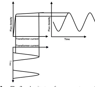
The transformer inrush currents are shown by the high saturation of the iron core during the switching-in of the transformer in Fig. 2. Fig. 2shows that remanence flux density in the core at the moment of switch on increases inrush current. Flux density is generated as the results of applied voltage; it is then cross-plotted with flux density-transformer current characteristics to show the inrush current magnitude.
[image:2.612.98.294.562.676.2]2.2.
Operation Principles of the Proposed Structure
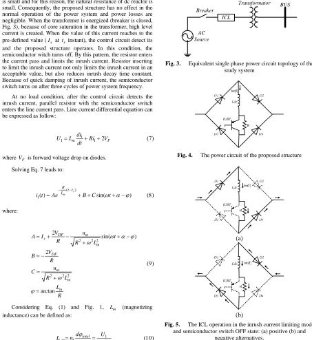
Fig. 3 and Fig. 4 show power circuit topology of the proposed structure and Equivalent single phase power circuit topology of the study system. This structure consists of a diode bridge, a small value of non-superconducting dc reactor (Ldc), semiconductor switch and a resistance that is parallel with the semiconductor switch (R).Before energizing transformer and in the normal operation of the power system, the semiconductor switch turns on and the resistor is bypassed. As mentioned above, the value of dc reactor is small and for this reason, the natural resistance of dc reactor is small. Consequently, the proposed structure has no effect in the normal operation of the power system and power losses are negligible. When the transformer is energized (breaker is closed, Fig. 3), because of core saturation in the transformer, high level current is created. When the value of this current reaches to the pre-defined value (Is at ts instant), the control circuit detect its and the proposed structure operates. In this condition, the semiconductor witch turns off. By this pattern, the resistor enters the current pass and limits the inrush current. Resistor inserting to limit the inrush current not only limits the inrush current in an acceptable value, but also reduces inrush decay time constant. Because of quick damping of inrush current, the semiconductor switch turns on after three cycles of power system frequency.
At no load condition, after the control circuit detects the inrush current, parallel resistor with the semiconductor switch enters the line current pass. Line current differential equation can be expressed as follow:
1
1 m 1 2 F
di
U L Ri V
dt
= + + (7)
where VF is forward voltage drop on diodes. Solving Eq. 7 leads to:
( )
1( ) sin( )
s m R
t t L
i t Ae B C ω α ϕt
− −
= + + + − (8)
where:
2 2 2
2 2 2
2
sin( )
2
arctan
m DF
s
m
DF
m
m
m
u V
A I t
R R L
V B
R u C
R L
L R
ω α ϕ ω
ω
ϕ
= + − + −
+ = −
= + =
(9)
Considering Eq. (1) and Fig. 1, Lm (magnetizing inductance) can be defined as:
1 1
1 total m
m
d U
L n
di di dt
ϕ
= = (10)
We know that the inrush current is concluded iron core in the transformer. Considering Eq. (10), if the iron core alternates between the saturation and non-saturation, Lm will has severe variation which cause high level inrush current in the transformer.
Operation conditions of the proposed ICL are shown in Fig 4. In the inrush current limiting mode, the semiconductor switch is OFF and the line current passes through “D1, Ldc, Resistor, D4” and “D3, Ldc, Resistor, D2” in positive (Fig. 4a) and negative (Fig. 4b) alternatives, respectively.
Transformator
ICL
BUS
AC Source
Breaker
Fig. 3. Equivalent single phase power circuit topology of the study system
Fig. 4. The power circuit of the proposed structure
(a)
(b)
Fig. 5. The ICL operation in the inrush current limiting mode and semiconductor switch OFF state: (a) positive (b) and
[image:3.612.76.529.176.670.2]3.
S
IMULATIONR
ESULTS OF THEP
ROPOSEDICL
O
PERATIONThe power circuit topology of the study system in Fig. 3 is used for simulation. The simulation parameters are as follows: Voltage Source:
220sin(ωt v) −rms; f =50Hz; The proposed structure parameters:
0.01 ;
dc
r = Ω Ldc=5mH; R= Ω8 ;
1 ;
DF SW
V =V = v
Transformer data:
5 ;
S= kVA
0.1 . ;
Leakage reactance= p u 0.1 . ;Air core reactance= p u
2%;
Magnetizing current= 1.Transformer ratio=
Load data: 10 ;
L
R = Ω LL=100mH.
where rdc, VDF and VSW are natural resistance of Ldc, forward voltage on diodes and forward voltage on semiconductor switch, respectively.
Fig. 6 shows the inrush current of transformer in no load condition without the proposed structure. The transformer is energized at t=0.5s. It is obvious that the inrush current level is several times larger than rated current of the power system equipments.
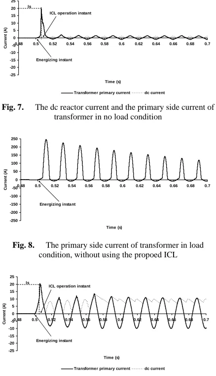
In no load condition, by using the proposed structure, when the inrush current reaches the pre-defined value (Is=20A), the proposed structure operates (at ts=0.5071s ) and the semiconductor switch turns off. So, the resistor enters the line current pass. Considering Fig. 7, in this condition, the proposed structure not only reduces inrush current in an acceptable value, but also, decrease time constant of line current (see Eq. (8)). Of course, considering rated power of the transformer, inrush current decay time constant is valued 0.2s .
In Fig. 8, the dc reactor and primary side current are shown in load condition without using the proposed structure. Similar to Fig. 6, high level current passes in the power system.
By using the proposed ICL in load condition, the inrush current is limited to an acceptable value (Fig. 9). As mentioned above, the semiconductor switch turns on after three cycles of the power system frequency because of quick damping of the inrush current. In addition, when the semiconductor switch turns on in the normal condition, because of using small dc reactor, the proposed structure has no effect on the normal operation of the power system.
-250 -200 -150 -100 -50 0 50 100 150 200 250
0.48 0.5 0.52 0.54 0.56 0.58 0.6 0.62 0.64 0.66 0.68 0.7
Time (s)
C
u
rre
n
t (
A
)
[image:4.612.314.533.74.454.2]Energizing instant
Fig. 6. The primary side current in no load condition
-25 -20 -15 -10 -5 0 5 10 15 20 25
0.48 0.5 0.52 0.54 0.56 0.58 0.6 0.62 0.64 0.66 0.68 0.7
Time (s)
Cu
rr
e
n
t (A)
Transformer primary current dc current Is
Energizing instant ICL operation instant
Fig. 7. The dc reactor current and the primary side current of transformer in no load condition
-250 -200 -150 -100 -50 0 50 100 150 200 250
0.48 0.5 0.52 0.54 0.56 0.58 0.6 0.62 0.64 0.66 0.68 0.7
Time (s)
C
u
rr
e
n
t (A)
Energizing instant
Fig. 8. The primary side current of transformer in load condition, without using the propoed ICL
-25 -20 -15 -10 -5 0 5 10 15 20 25
0.48 0.5 0.52 0.54 0.56 0.58 0.6 0.62 0.64 0.66 0.68 0.7
Time (s)
C
u
rre
n
t (
A
)
Transformer primary current dc current Is
Energizing instant ICL operation instant
Fig. 9. The dc reactor current and the primary side current of transformer in load condition, using the proposed ICL
4.
C
ONCLUSION [image:4.612.83.299.556.647.2]5.
R
EFERENCES[1] H. Seo, Ch. Kim, S. Rhee, J. Kim, O. Hyun, “Superconducting Fault Current Limiter Application for Reduction of the Transformer Inrush Current: A Decision Scheme of the Optimal Insertion Resistance,”, IEEE Trans., Appl. Supercond., vol. 20, no. 4, pp. 2255-2264, Agu. 2010.
[2] H. Shimizu, K. Mutsuura, Y. Yokomizu, T. Matsumura, “Inrush-Current-Limiting With High TC Superconductor,”
IEEE Trans., Appl. Supercond., vol. 15, no. 2, pp. 2071-2073, Jun. 2005.
[3] A. A. Adly, “Computation of Inrush Current Forces on Transformer Windings,” IEEE Trans., Magn., vol. 37, no. 4, pp. 2855-2857, Jul. 2001.
[4] John H. Brunke, Klaus J. Fröhlich, “Elimination of Transformer Inrush Currents by Controlled Switching— Part I: Theoretical Considerations,” IEEE Trans. Power Del., vol. 16, no. 2, pp. 276-280, Apr. 2001.
[5] John H. Brunke, Klaus J. Fröhlich, “Elimination of Transformer Inrush Currents by Controlled Switching— Part II: Application and Performance Considerations,”
IEEE Trans. Power Del., vol. 16, no. 2, pp. 281-285, Apr. 2001
[6] V. Molcrette, J. Kotny, J. Swan, J. Brudny, “Reduction of Inrush Current in Single-phase Transformer Using Virtual Air Gap Technique,” IEEE Trans. Magn., vol. 34, no. 4, pp. 1192-1194, Jul. 1998.
[7] Sami G. Abdulsalam, Wilsun Xu, “A Sequential Phase Energization Method for Transformer Inrush Current Reduction—Transient Performance and Practical Considerations,” IEEE Trans. Power del., vol. 22, no. 1, pp. 208-216, Jan. 2007.
[8] J. H. Brunke, “Elimination of transient inrush currents when energizing unloaded power transformers,” Doctoral Dissertation, no. 12791, ETH Zurich, 1998.
[9] H. Seo, Ch. Kim, S. Rhee, J. Kim, O. Hyun, “Superconducting Fault Current Limiter Application for Reduction of the Transformer Inrush Current: A Decision Scheme of the Optimal Insertion Resistance,” IEEE Trans., Appl. Supercond., vol. 20, no. 4, pp. 2255-2264, Agu. 2010.
[10] M. Tarafdar Hagh and M. Abapour, “DC reactor type transformer inrush current limiter,” IET Electr. Power Appl., vol. 1, no. 5, pp. 808–814, Sept. 2007.
[11] M. Tarafdar Hagh, M. Jafari and S. B. Naderi, “Transient Stability Improvement Using Non-superconducting Fault Current Limiter,” in Power Electronic and Drive Systems
and Technologies Conference, Tehran, IRAN, PEDSTC,
2010, pp. 367-370.
[12] M. Tarafdar Hagh, S. B. Naderi and M. Jafari, “Application of Non-superconducting Fault Current Limiter to Improve Transient Stability,” in International
Conference on Power and Energy, Kuala Lumpur,