RECONSTRUCTION
INTRODUCTION
S. J. Wormley and D. O. Thompson Ames Laboratory, USDOE
Iowa State University Ames, IA 50011
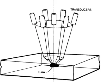
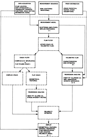
A mu1tiviewing transducer, described in the companion paper in this volume (1) has been designed and developed to exploit advances in theoretical inverse elastic wave scattering in the long and inter-mediate wavelength regime. The mu1tiviewing transducer concept is shown in Fig. 1. In addition, and as part of a broader effort to develop a decision tree for general flaw characterization shown in Fig. 2, a first generation set of post-processing data procedures has been developed and implemented for use with the mu1tiprobe instru-mentation. These procedures provide a 3-D reconstruction and characteri-zation of volumetric flaws (size, shape, orientation and acoustic
impedance estimates) and are shown by solid boxes in Fig. 2.
Fig. 1. Mu1tiviewing Transducer Concept - the six parimeter trans-ducers may be set as a group to any angle 0-30° with respect to the normally incident center transducer. Each of the six parimeter transducers can be independently adjusted along its own axis allowing equalization of propagation times for any pitch-catch or pulse-echo combinations.
[image:1.482.142.339.398.558.2]Fig. 2.
DATA ACQUISITION (FLAW LOCATION, HOST ATTENUATION (w). TRANSDUCER TRANSFER
...---1 FUNCTtONS, ANGLE SETTING INFORMATION, NOISE)
MEASUREMENT SEQUENCE
(RAW, SCATTERED WAVEFORMS)
PRIOR INFORMATION
(PRIOR STATISTICAL HISTORY, OTHER ASSUMPTIONS)
---1---MEASUREMENT MODEL
(SCATTERING AMPLITUOES, IMPULSE RESPONSES)
(1)
,.---~----
-,
: FLAW FILTER :
I I
I (EITHER CRACK OR I
I
VOLUMETRIC FLAW) :, I
1'--- '
r
-; CRACK FILTER I
I I
~(COMPLEX (E G BIFURCATED):
: FLAT (PLANE) ~RACK I :
L---
r -,,---
J
r---..Jt., ..
~
---,
I I • •
I COMPLEX CRACK I I FUT CRACK I
I I • •
I I I (GEOMETRICAL I
: : : FEATURES) :
: I I I
L __________ .J L---
1
---J
r---
---1I AEGAESStON ANALYSIS I
I ,
• I
I ("BEST FIT" ELUPSE 2-D, I 1 STRESS INTENSITY FACTOR) t
,
,
VOLUMETRIC FLAW
CHARACTERIZATION (SIZE ESTIMATES)
(2 )
REGRESSION ANALYSIS .... ("BEST FIT" ELUPSOID 3-0, _
SIZE. ORIENTATION, ACOUSTIC IMPEDANCE)
(3.4)
L--r--~----J
U---~
•
:;~~.,'o'r."!o._----...J
L-_ _ _ _ _ _ _ _ _ ~I :
I I
L ______ 1 ______ J
r----Di!C.;----,
: (GEOMETRICAL FEATURES, : L-_ _ _ _ _ _ _ _ _ _ _ _ _ _ _ _ _ .~: ~~;~~N~6:~:~.
:
: ~~~~nl:EX)
i
L _____ ~:..·) _____
J
[image:2.482.98.385.107.558.2]The procedures consist of: the acquisition of backscatter waveforms from several independent look angles; corrections for the effects of attenuation, diffraction, interface loses; deconvolution by trans-ducer reference data; radius estimation using the inverse Born approxi-mation, determination of parameters describing an ellipsoidal model that "best fits" the data.
As a subsection to the development of the decision tree, a study has been initiated to examine systematic errors that are encountered in the reconstruction process. Emphasis is given to the effects of variable aperture and the number of independent and redundant look angles upon the final reconstruction results assuming various random errors in the determination of flaw size utilizing the inverse Born sizing procedure.
Experimental Procedure
The details of volumetric flaw characterization currently in place include the following elements:
1. Data Acquisition - Backscatter waveforms from a target flaw are digitized for thirteen independent pulse-echo, pitch-catch measure-ments.
2. Measurement Model - The waveforms are corrected for the effects of attenuation, diffraction, and interface loses using the measurement model (2). Transducer references are deconvolved resulting
in absolute scattering amplitudes.
3. Inverse Born approximation - The inverse Born sizing procedure (3) is used to estimate the tangent plane to centroid distance (Re) for each absolute scattering amplitude.
4. Regression Analysis - Six geometric parameters (three semi-axes and three Euler orientation angles) that describe the "best fit"
ellipsoid to the data are derived by regression analysis (4). The
regression inputs include the radius estimates Re(i) and their associated angles ai and ~i'
The use of this "best fit" ellipsoid technique was suggested by Kohn and Rice (5) as a way to approach the inverse problem in the long wavelength approximation utilizing Eshe1by's strain tensor (6,7). It is quite general and permits descriptions of either cracks (2D) or inclusions and voids (3D) to be obtained. For example, a
2D element is closely approximated by a determination of three semi-axes if one at the semi-axis is small compared with the other two. Results from fracture mechanics show that failure initiating microcracks nucleate selectively about inclusions of various compositions and eventually grow into cracks under flaw growth conditions. While this assumption does not focus attention on the failure initiating microcracks per se, it does permit reasonable descriptions of the inclusions
(or voids) that are necessary to nucleate the microcracking to be obtained. The use of the front surface echo analysis, which yields values of the acoustic impedance of the scatterer, assists fn this matter. This measurement permits an estimate of the identity of
not there are likely to be surrounding microcracks. Evans et a1. have demonstrated this effect in ceramics (8). Ellipsoidal assumptions provide a convenient working base for the purposes of instrumental and signal processing development.
A
simple procedure was adopted to develop the "sensitivity" analysis. First, values of the radius estimates Re(i) were calculated for a set of parameters C1, ---, C6 that describe 3 semi-axes and the orientation of the ellipse. Re , the tangent plane to centroid distances, can then be written as2 cosa + TO,2) sina sina + T(l,3) cosa)2 R = [ C1(T(l,l) sina e
+ 2 C2(T(2,l) sina cosa + T(2,2) sina sina + T(2,3) cosa) 2
+ 2 C3(TO,l) sina cosa + TO,2) sina sina + TO,3) cosa) 2
1
~where T (a function of C1' ---, C6) is the Euler transformation matrix using the convention as defined by Goldstein (9) relating the ellipsoid principle axis system to the part (or sample) axis system.
0)
These radius estimates Re(i) were then subjected to the regression analysis and results obtained for the three semi-axis and the
three Euler angles that describe the best fit ellipsoid. The best fit parameters were then compared with the assumed values of the simulated flaw for a variety of apertures and data patterns. In the no error case, results obtained simply reiterate the initial assumptions.
In order to examine the effects of measurement error in Re upon the reconstruction parameters, the exact values for Re are replaced by R~ with random errors added, i.e.,
R~ (with error) = Re (1 + n)
where n is randomly generated such that -O.l<n<+O.l. Using this approach the "best fit" ellipsoidal parameters can then be compared with assumed values and the effect of error in ~e' aperture, and/or the numbers and patterns of look angles may be analyzed.
We used all seven of the transducers in the configuration shown in Fig. 1. For these seven, there are 7C2 or 21 combinations of pitch-catch patterns. Of the 21, nine are spatially redundant leaving twelve independent pitch-catch look angles. The addition of the
(2)
seven pulse-echo signal results in 19 independent look angles. Thirteen were chosen for variable aperture analysis.
RESULTS
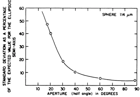
of the mean values of the six "best fit" ellipsoidal parameters to expected values showed that the mean approaches the expected value within one percent. However, the sample standard deviation of the ellipsoidal parameters approaches an asymptotic limit. Table 1 shows the standard deviation as a percentage of expected value for the ellipsoid semi-axes in the three cases studied. Column one is the transducer angle with respect to the normal (aperture half angle) in degrees. Columns two through four are the values of the standard deviation as a percentage of expected value for the three cases:
200~m x 400~m oblate spheroid; l14~m sphere; and a 400~m x 200~m
prolate spheroid. It should be noted that these values are "mean" values for the three semi-axis Cl' C2 and C3.
Table 1. Error as a function of aperture.
Aperture (half angle)
5° 15° 20° 25° 30° 40° 60° 90°
2-1 Oblate Spheroid Error* 80.7 20.9 14.0 9.8 7.0 5.9 5.3 5.9 Sphere Error* (52.3) 40.2 18.6 10.4 5.4 3.8
2-1 Prolate Spheroid Error* 40.7 29.5 21.0 6.8 3.8
*Standard deviation as a percentage of the expected value for the ellipsoid semi-axes (combined).
The results from Table I are plotted in Figs. 3, 4, and 5 for the three simulated flaws. In all cases, it is evident that the reconstruction error dimishes with increasing aperture. In Fig. 3, the 2:1 oblate spheroid was oriented horizontally such that the apex of the transducer aperture cone is normal to the surface of minimum curvature. In Fig. 4, the orientation of the sphere has no meaning. And, in Fig. 5, the 2:1 prolate spheroid was oriented such that the apex of the transducer aperture cone is normal to the surface of maximum curvature.
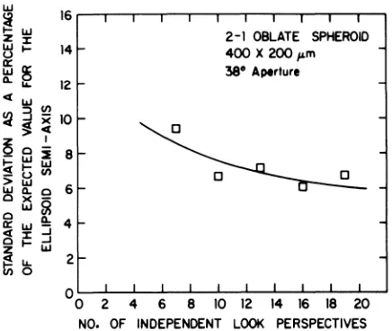
A preliminary analysis of the effect of the number of independent look angles was done using the 2:1 oblate spheroidal case at an aperture of 38°. Of the 19 spatially independent look angles available with a set of seven transducers, symetric patterns of 7, 10, 13, 16 and 19 were chosen. Figure 6 shows the trend of decreasing error with increasing number of look angles.
Discussion of Results
0
0
til
Il.
1.LJ::::i
~~
z
I.LJI.LJ
U:l:
O:~
I.LJ
1l.!3
et~
til !!!
etl.LJ)( ::let z....J I
Q~2
!Ii
I.LJs;fi}tIl
I!!:t;
o~
0:)(
etl.LJ
0
zl.LJ et:l:
~~
til
~
0
60
50
40
30
20
10
2-1 OBLATE SPHEROID 200 X 400 fLm
~ W 30 40 50 60
ro
00 ~ APERTURE (half angle) In DEGREESFig. 3. Aperture vs reconstruction error for a 200 x 400 ~m oblate spheroid (Pancake).
SPHERE 114 fLm
o
"'0
---0_
---0
10 20 30 40 50 60 70 80 ~ APERTURE (half angle) in DEGREES
[image:6.482.106.372.101.287.2] [image:6.482.100.374.414.604.2]0 wO
l!)Ul 60
«9: t-...J z...J WW
u 50
a::w WI [1.t-«a:: 40
0
Ul~Ul «w
x
z::>« 30 O...JI -«~ !;:(>w-OUl >w 20
Wt-Ou
W 0[1. a:: x 10 «w 0 ~~
tnt-
"'-0
Fig. 5. Aperture spheroid
2-1 PROLATE SPHEROID 400 X 200 t'-m
\~
0
90
APERTURE ( holf - onole) In d'Qrees
vs reconstruction error for a 400 x 200~m prolate (cigar) .
2 4 6 8
2-1 OBLATE SPHEROID 400 X 200 I'm
38° Aperture
o
10 12 14 16 18 20 NO. OF INDEPENDENT LOOK PERSPECTIVES
[image:7.482.93.379.86.279.2] [image:7.482.139.357.395.579.2]of 2n) the leverage becomes sufficient to resolve any shape and orienta-tion; however, practical considerations will restrict the usable
aperture to smaller angles. An increased aperture results in greater effective surface illumination and therefore reconstruction is less sensitive to error in the tangent plane to center estimates.
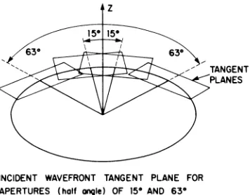
z
INCIDENT WAVEFRONT TANGENT PLANE FOR APERTURES (half CI/19le) OF 15° AND 63°
TANGENT PLANES
Fig. 7. Incident wavefront tangent plane for aperture (half angle) of 15° and 63°.
It would be expected that the prolate spheroid would be the most sensitive to error. The date confirm that hypothesis. Further work in progress, but not reported here indicates that the sensitivity also increases as the aspect ratio of the ellipsoid increases. Various methods of weighting the data (R~(i» are being examined in continuing work.
Practical considerations such as processing time and memory
[image:8.482.164.342.205.344.2]ACKNOWLEDGEMENT
The Ames Laboratory is operated for the U.S. Department of Energy by Iowa State University under Contract No. W-7405-ENG-82. This work was supported by the Director of Energy Research, Office of Basic Energy Sciences.
REFERENCES
1. D. O. Thompson and S. J. Wormley, "Long and intermediate flaw reconstruction", this volume.
2. R. B. Thompson and T. A. Gray, "A model relating ultrasonic scattering measurements through liquid-solid interfaces to unbounded medium scattering amplitudes", J. Acoust. Soc. Am. 74(4), October 1983.
3. J. H. Rose, R. K. Elsley, B. Tittmann, V. V. Varadan and V.
K. Varadan, "Inversion of ultrasonic scattering data", Acoustic, Electromagnetic and Elastic Wave Scattering - Focus on the T-Matrix Approach, Pergamon Press, 1979.
4. D. K. Hsu, J. H. Rose and D. O. Thompson, "Ultrasonic 3-D recon-struction of inclusions in solids using the inverse Born algorithm", J. App1. Phys. 55(1), 162 (1984).
5. W. Kohn and J. R. Rice, "Scattering of long wavelength elastic waves from localized defects in solids", J. App1. Phys. 2Q., 3346 (1979).
6. J. D. Eshelby, Proc. Roy. Soc. London, A24l, 376 (1957). 7. J. D. Eshleby, in Progress in Solid Mechanics, I. N. Sneddon
and R. Hill, Eds. (North Holland-Amsterdam, 1961), Vol. 2, pp. 89-140.
8. A. G. Evans, M. E. Meyer, K. W. Fertig, B. I. Davis and H. R. Baumgartner, "Probabilistic models for defect initiated fracture in ceramics", Proceedings of DARPA/AFML Review of Progress in QNDE", AFWAL-TR-80-4078, 1980, pp. 636-645.