Article
Influence of Soft Magnetic Materials Application to
Squirrel Cage Induction Motor Design and
Performance
Yannis L. Karnavas
a,*
and Ioannis D. Chasiotis
bElectrical Machines Laboratory, Department of Electrical & Computer Engineering, Faculty of Engineering, Democritus University of Thrace, Xanthi, Hellas (GR)
E-mail: a[email protected] (Corresponding author), b[email protected]
Abstract.Most of the electrical machines design studies found in literature lie on the concept that the design under investigation (and optimization) focuses mainly on the geometrical aspects of the machine and thus takes into account only a certain ferromagnetic material (i.e. iron) for its parts. These studies, give little or no information about the influence of material
alternatives on the same (and optimized) design. From a manufacturers’ point of view
though, this information is crucial especially nowadays that there are a lot of commercially available materials in the market. In this context, this paper presents the results of a research project in the design stage of an energy efficient three phase squirrel cage induction motor (SCIM), by investigating the effects of several soft magnetic materials (adopted for its stator and/or its rotor parts) on multiple quantities of primary concern such as: efficiency, power factor, output torque, losses, weight and cost. After a brief proposed design procedure, a total of twenty-two different materials from recent manufacturers’ data were examined. Also,
the main electromagnetic analysis was performed through commercial analysis software. Simple ranking methods are also proposed here for different application areas and the results obtained are then thoroughly discussed and commented.
Keywords: Soft magnetic materials, electrical machine design, squirrel-cage induction motor, motor performance.
ENGINEERING JOURNAL Volume 21 Issue 1
1.
Introduction
Nowadays, induction motors account for approximately 50% of the overall electricity use in industrialized countries. Moreover, in the agricultural and commercial sectors, power consumption by A.C. motors is quite substantial. It has been estimated that, the energy which is consumed by a motor during its life cycle is 60-100 times the initial cost of the motor [1]. Therefore, the good efficiency of such a motor is of great importance both during its manufacturing/selection and throughout its operation. Additionally, a big difference in energy savings would be possible even by a small increase in its efficiency improvement.
Since 2000, the European Scheme to designate energy efficiency classes for low voltage A.C. motors has been in operation. It is based on a voluntary agreement between the European Commission and CEMEP, the European Committee of Manufacturers of Electrical Machines and Power Electronics [2]. This Scheme
classifies induction motors into three efficiency bands, from “EFF3” (lowest) to “EFF1” (highest). This
agreement should stimulate the manufacturers in the development of new ranges of high efficiency motors that requires an accurate motor design, the adoption of new materials and innovative technologies [3].
Undoubtedly, the magnetic material plays a significant role, also in the improvement of a motor’s
performance [4]. With respect to this goal, its main features are the magnetic permeability and the specific
losses. Moreover, the choice of “suitable” electrical steel depends on several aspects such as cost, workability,
annealing (when needed), “business tradition” and storehouse demands. Developing new ranges of high
efficiency motors, the choice of a magnetic material is an “open problem” today. For example, (if the overall
cost is not of primary concern), it is well known that incorporation of copper for the rotor bars and end rings of a squirrel cage induction motor (SCIM) in place of aluminum would result in attractive improvements in motor energy efficiency [5], [6].
At the same time, the design procedure -in terms of dimensions- of a three-phase SCIM depends on several parameters such as desired torque at a specific speed, the type of the enclosure, the type of cooling, the duty cycle of the load and the intensiveness that the electric and magnetic circuits are used. The reader can refer to the relevant literature i.e. [7]-[12], for an in depth survey on the detailed analytical formulas involved. Also, during the last decade, many analytical studies were performed regarding multi-objective optimization techniques applied in the design process using classical models [13]-[15]. The potential of artificial intelligence methods like genetic algorithms and neural networks have also been investigated i.e. [16]-[19]. To the authors' knowledge extend though, the main drawback of these studies lies on the concept that the motor design under investigation and optimization, consisted of certain (and fixed) materials, so there was no information about the influence of material change on the same (and optimized) design.
The aim of this paper is to present the main aspects of the influence on the performance (either towards improvement or weakening) of industrial three-phase SCIMs when several electric steels are considered for
their stator and/or rotor cores. The paper is organized as follows: In Section 2, the SCIM’s design
specifications, their relative constraints and the design procedure are briefly stated in order to reach a pre-optimized model for further reference. In Section 3, the application (by means of accurate simulation) of 22
today’s commercially available materials for the construction of such a motor will be shown, along with the
results of several simulations and post-calculations. Moreover, a simple strategy is proposed regarding the suitability of these materials and the specific requirements of each application (i.e. traction or industrial motors). This strategy comprises of two ranking procedures in order to choose an appropriate material from a techno-economical perspective (or manufacture's point of view). An overall analytical discussion is given in Section 4 of this paper, while Section 5 concludes this work.
2.
Squirrel Cage Induction Motor Design
2.1. Design Specifications, Data and Constraints
will be stated in the next paragraph which refers to their calculation. Moreover, a set of constraints should be predefined pertaining magnetic and constructional quantities. This constraint set is shown in Table 2. It should be stated that the maximum flux densities values appearing in this Table, are necessary so the magnetic material avoids saturation during motor's operation.
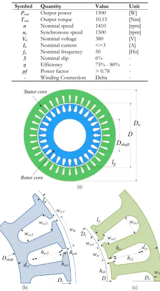
Table 1. Three-phase SCIM specifications (desired) data.
Symbol Quantity Value Unit
Pout Output power 1500 [W]
Tout Output torque 10.15 [Nm]
n Nominal speed 1410 [rpm] ns Synchronous speed 1500 [rpm]
Vn Nominal voltage 380 [V]
In Nominal current <=3 [A]
fn Nominal frequency 50 [Hz]
S Nominal slip 6% -
η Efficiency 75% - 80% - pf Power factor > 0.78 - - Winding Connection Delta -
(a)
(b) (c)
[image:3.595.141.455.161.730.2]Table 2. Basic magnetic and constructional specifications (constraints) for high efficiency SCIM.
Symbol Quantity Value Unit
Bav Air-gap flux density 0.9 [T]
Bcsmax Maximum stator core flux density 2.0 [T]
Bcrmax Maximum rotor core flux density 2.0 [T]
Btsmax Maximum stator teeth flux density 2.2 [T]
Btrmax Maximum rotor teeth flux density 2.2 [T]
δs Stator's conductors current density 3.5 [Α/mm2]
Ler Rotor bars' ring length 10 [mm]
Ac Special electric loading 1.23 [At/m]
L/τp Design criteria 1.5 -
sf Active length factor 0.97 -
kw Stator winding factor 0.955 -
ψ Parallel circuits number 1 - kr Rotor correction factor 0.95 -
rcs Stator conductor-to-slot area ratio 0.6 -
2.2. Design Calculations
The design phase is based on equations found in [7]-[9], after a thorough study and adaptation of the relevant
classical theory to our motor’s requirements. Since the focus of this work lies mainly on the cores' materials selection and their influence on the motor's behavior, only the main geometrical parameters (as in Fig. 1) calculation procedure will be shown here subject to the relevant constraints. Also, this procedure can be followed quickly and easily if the main designer's concern is the machine's nominal quantities.
2.2.1. Preliminary calculations
The motor's active power, apparent power and it’s per phase stator current are given by:
3 , , 10
cos 3 cos
o in o
in in sph
n
P P P
P S I
V (1)
For commercial motors above 1kW, the numbers of stator and rotor slots (Ss, Sr) are usually selected as 36 and 28 respectively. If we consider (m=3) the number of phases and (p=4) the number of poles, the stator's distribution factor can be defined as:
3 sin 4 9 3
10 0.5 10
sin 4 9
d
s s
m pm k INT
p S S
(2)
Then, the per phase magnetic flux (Φ), the per phase number of conductors (Ns), the total number of stator's
conductors (Zs) and the number of conductors per stator's slot (Zss), can be computed as follows:
3 10
4.44
sph
e s w E
f N k
(3)4.44 sph s e d E N
f
k (4)
2
s s
Z m N (5)
s ss s Z Z S (6)
where Esph=0.97Vn is the per phase stator induced voltage for delta connection, and Ψ the number of
conductor parallel paths (here is equal to 1). From the design criteria (L/τp), which has been set to 1.5 for high
efficiency motors, the air-gap diameter as well as the motor's core length can then be calculated:
2
60
in o s
[image:4.595.138.463.105.297.2]3
3 60
10
( / )
in
o S P
S p D
C n L
(8)
where Co is the machine output factor given by:
3 2
1.11x10
o av c w
C
k (9)Finally, the active motor cores' length as well as the air-gap length can be computed:
i f
L s L (10)
6560 3 06
2280
g
l . -D
(11)
2.2.2. Stator part geometry
With respect to Tables 1 and 2, the maximum flux density constraint in the stator core (Bcsmax), influences
both the stator core and stator slot depths in the following way:
min 3 10 4 cs i d L (12.a) min
max 103 2
2
o cs
ss
D D d
d (12.b)
Also, the maximum flux density constraint in the stator teeth (Btsmax), influences both the stator teeth and
stator slot widths as:
min 103 2.2 ts r i pΦ w
S L (13.a)
( ss) s ss
ts
s
D d S w w
S
(13.b)
min
max ( ss) ts
ss
s
D d w
w
S
(13.c)
The outer stator diameter Do is determined here by using Eqs. (12.b)-(13.c) iteratively until the relevant
constraints are met. Finally, the stator slot width at teeth, the stator slot width at opening and the stator slot width at end, are given by:
3 max 1 10 ts i ss s p D L w S (14.a) 2
( ss 5) s ts
ss
s
D d S w
w
S
(14.b)
3
( 2 ss) s ts
ss
s
D d S w
w
S
(14.c)
Now, with respect to Fig. 1(c), the relevant stator slot heights are easily obtained as hs0=dss/30, hs1=dss/15,
hs2=dss-hs0-hs1.
2.2.3. Rotor part geometry
Continuing for the motor’s rotor parameters, the main calculations can start by defining its diameter:
g
2
r
D D l (15)
The maximum flux density constraint in the rotor core (Bcrmax), influences the rotor core depth:
3 max 10 2 cr cr i d L (16)
2
2
r shaft cr
sr
D D d
d (17)
By using Eqs. (15)-(17) we can determine, iteratively again, the maximum shaft diameter for which the rotor core is not being saturated. In turn, we can obtain more additional parameters by minimizing the rotor copper losses:
2
cu
r r br
P R I (18)
where Rris the rotor’s total resistance:
2
2
br er
r eff eff r rr
br
s r
r I
R k r
I
N N
(19)
In Eq. (19), the (Nseff / Nreff) is the so called active (effective) stator to rotor turns ratio, rbr and rrr are the rotors’ bars and rotors’ rings resistances respectively and Ibr and Irrare the rotors’ bar and rotors’ ring currents
as per following,
2
eff
s w S
eff
r r
N mk N
N S (20)
5 2 2.7x10 0.8 r s br s sph S L r Z I (21)
5 2.7x10 3 5 r shaft rr r shaft D D r D D (22)2 w s sphcos
br
r mk N I I S
(23) r rr br S I I p (24)Moreover, the rotor’s teeth width is given by:
( r sr) r sr
tr
r
D d S w
w
S
(25)
where the rotor slot width is,
2 2 4 0.4 4 br sr sr a w d (26)
and the rotor bar’s cross sectional area can be derived by:
0.8 s sph
br s r Z I a S
(27)Now, with respect to Fig. 1(b), it is dsr=hsr0+hsr1+hsr2+wsr3/2. Simulation trials reveal that if we set
hsr0=hsr1=0.6mm, we succeed better results in terms of desired quantities (torque, efficiency, power factor).
Finally, hsr2 can then be easily obtained.
2.3. Design Results
The overall calculation results for the motor’s geometry are shown in Table 3. These values are imported into
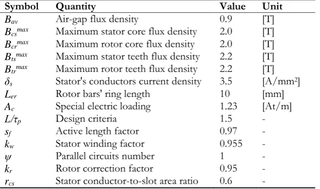
the ANSYS Electromagnetics Suite software. The RMxprt model (design mode) is derived first and the Maxwell 2D environment is called afterwards for transient simulation performance. Figure 2 shows the developed flux density distribution of the designed SCIM as well as the flux lines path at an instant of running condition. It can be seen that the field constraints which were set are well satisfied. Figure 3 depicts the starting/running torque time response and the current-speed characteristic curve as taken by the software’s
Table 3. Calculated geometrical parameters of the three-phase SCIM under study.
Quantity Stator Value [mm] Rotor Value [mm]
Slot width at teeth wss1 1.000 wsr1 0.429
Slot width at opening wss2 2.252 wsr2 2.480
Slot width at end wss3 3.650 wsr3 5.200
Teeth width wts 5.690 wtr 6.134
Slot height at teeth hs0 0.333 hsr0 0.600
Slot height at opening hs1 0.666 hsr1 0.600
Slot height at end hs2 8.050 hsr2 7.600
Iron bore width wbi 7.414 lg 0.290
Core depth dcs 9.239 dcr 9.239
Airgap diameter D 89.000 Dshaft 46.636
Outer diameter Do 125.668 Dr 88.420
(a) (b)
Fig. 2. Designed 1.5kW 3-phase SCIM distributions of a) flux density and b) flux lines (under running condition).
(a)
(b)
Fig 3. Designed 1.5kW 3-phase SCIM simulated response characteristics of a) starting torque as a function of time and b) starting current as a function of speed.
[image:7.595.97.501.115.430.2] [image:7.595.169.432.468.717.2]3.1. Simulation Procedure and Preliminary Results
The application of the stator and rotor core materials follows. At this point, it should be stated that the authors tested the use of different materials for the two cores, and it was found that there is no significant improvement in any quantity of concern. Moreover, the overall cost was found clearly larger. Thus, only results with the same material tested for both cores will be shown here (although some discussion will be given on that later). A total of 22 different materials are being considered. Ten of them were available through
the ANSYS® EM Suite software’s database, while the rest twelve were processed and incorporated to the
database by the authors. In order to update the software’s database, real data from commercially available
materials were firstly retrieved (i.e. [20]-[22]) and secondly, data-entry of the relative B-H curves of these materials as well as their properties i.e. bulk conductivity, mass density etc., has been conducted using the
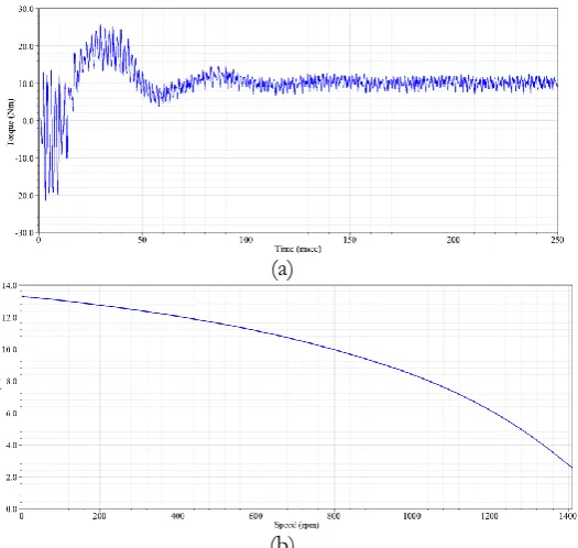
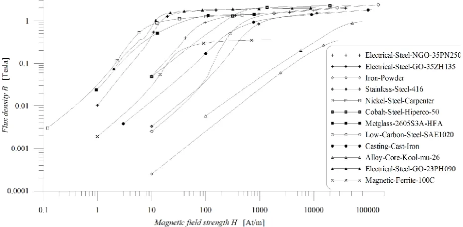
software’s capabilities [23]. For reference reasons, the B-H curves of the new (added) materials are shown in Fig. 4. Especially for the rotor bars, it has been found in [24] that the utilization of copper instead of aluminum is much more expensive in manufacturing terms and in many situations increases the overall cost even more. In this context, aluminum was retained in every simulation that followed. By using one of the materials each time, numerous simulations were performed and the values of important quantities (namely: efficiency (η), output torque (T), power factor (pf), and phase current (Iph)) of the SCIM were recorded. These recordings
are shown in Table 4 (which is sorted by efficiency in descending order). From Table 4 it can be seen that
the materials “Iron-Powder”, “Magnetic-Ferrite-100C”, “Mu-metal” and “Alloy-Core-Kool-mu-26” cannot reach the
[image:8.595.116.475.447.750.2]predefined desired nominal torque of 10.15Nm. Moreover, these four materials score a very low efficiency ratio and they also exhibit high stator currents. Thus, these materials are disqualified at first place. Further, some more candidate materials may also be rejected. By observing the performance regarding the predefined desired efficiency (set in the range 75%-80%), materials “Electrical-Steel-NGO-35PN250”, “M19-24G”, “Μ19 -24G-2DSF-920”, “Steel-1008”, “Steel-1010”, “Steel-1018”, “Steel-1010-2DFSO-950”, “Stainless-Steel-416”, and “Castings-Cast-Iron” are also being disqualified.
Table 4. Influence of the 22 examined soft magnetic materials on the SCIM’s main operational performance quantities (sorted by efficiency).
Soft Magnetic Material
(Commercial Name) Efficiency (%) Torque (Nm) Power factor Current (A) Phase
Iron-Powder 1.050 0.840 0.846 21.117 Magnetic-Ferrite-100C 1.178 0.928 0.834 20.929
Mu-metal 2.515 1.720 0.788 19.362
Alloy-Core-Kool-mu-26 3.314 2.118 0.765 18.623 Castings-Cast-Iron 47.991 10.347 0.627 7.486
Μ19-24G-2DSF-920 55.389 10.314 0.674 6.278 Stainless-Steel-416 59.572 10.280 0.652 5.787 Steel-1010-2DFSO-950 67.561 10.224 0.701 4.738
M19-24G 68.459 10.215 0.729 4.495
Steel-1010 72.539 10.194 0.754 4.099 Steel-1018 73.015 10.197 0.760 4.038 Elec.-Steel-NGO-35PN250 73.815 10.188 0.772 3.935 Steel-1008 74.415 10.183 0.781 3.857 Metglas-2605S3A-HFA 75.245 10.178 0.794 3.749 Low-Carbon-St.-SAE1020 75.666 10.176 0.802 3.694
Cobalt 76.822 10.168 0.823 3.541
Nickel-Steel-Carpenter 78.555 10.160 0.861 3.310
Nickel 78.998 10.156 0.876 3.249
Elec.-Steel-GO-23PH090 79.505 10.155 0.886 3.180 Elec.-Steel-GO-35ZH135 79.649 10.155 0.890 3.160 Cobalt-Steel-Hiperco-50 79.900 10.153 0.897 3.124
Fig. 4. B-H curves of the twelve additional (and commercially available) materials used for SCIM stator and rotor cores.
At this point, there are only 9 out of 22 candidate materials left, and the material cost is now considered. A thorough search in the international material market has been conducted (i.e. www.infomine.com, prices on 16/02/2016) and Table 5 shows the remaining materials’ performance quantities along with the SCIM’s total
net weight and the corresponding cost per kilo in ascending order. Note that torque has been left out since
it is satisfied now by all the materials. The next set of simulations, refer to the motor’s material consumption
for both stator and rotor parts. Considering the geometry of Section 2, along with the materials cost, the first part of Table 6 (columns 2-4) summarizes the armature’s (stator) core steel consumption (SCSC), the rotor’s
core steel consumption (RCSC) and the overall motor’s cost for the remaining materials.
3.2. Proposed Ranking Methods and Further Results
So far, a detailed assessment of different commercially available materials was made on the performance of an appropriately designed SCIM. At the same time it is known that feasibility studies are one of the most important parts of decision making for project investment [25]. Thus, two simple but effective ranking procedures are proposed here, so the designer (or the manufacturer) can be able to use the results of these procedures as an aid decision making tool.
a) Top score ranking procedure: Let say there are N performance quantities, including the quantity for which there is the main concern (and for which some materials perform similarly). Then, excluding the latter, every material shown in Table 5 takes 1 point for each of the rest N-1 quantities regarding their sorted position. It
should be noted here, that this kind of ranking, has a “negative” meaning, that is, the longer the distance one material has from the 1st place, the more points it takes. In other words, the material which gathers the least
total points will be the “winner” and that is translated as the material with the best mean performance in
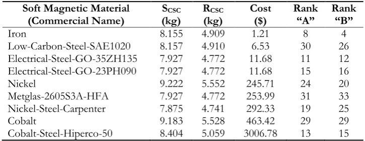
regard to the N-1 quantities. Let us consider example “A”, where it is assumed that the main quantity under concern is the motor’s cost. It is possible for some materials with relatively similar (or same) cost to exhibit
better performance regarding the nominal desired parameters of the motor (i.e. electrical steels “GO-35ZH135” and “GO-23PH090”). The first is at the 3rd place regarding efficiency, at 3rd place regarding
power factor, at 3rd place regarding phase current and at 2nd place regarding total motor’s weight. So, its ranking will be 3+3+3+2=11 points. This score is by far better than the second’s one with a corresponding
[image:9.595.69.531.79.305.2]Table 5. Candidate material performance regarding to efficiency, power factor, phase current, total weight and commercial cost (sorted by the latter).
Soft Magnetic Material
(Commercial Name) Efficiency (%) Power factor Current (A) Phase Weight (kg) Total ($/kg) Cost
Iron 80.004 0.900 3.110 7.861 0.092
Low-Carbon-St.-SAE1020 75.666 0.802 3.694 7.863 0.500 Elect.-Steel-GO-35ZH135 79.649 0.890 3.159 7.676 0.920 Elect.-Steel-GO-23PH090 79.505 0.886 3.179 7.676 0.920
Nickel 78.998 0.876 3.249 8.726 16.630
Metglas-2605S3A-HFA 75.245 0.794 3.749 7.676 20.000 Nickel-Steel-Carpenter 78.555 0.861 3.309 7.634 23.170
Cobalt 76.822 0.8236 3.541 8.694 31.500
[image:10.595.81.514.129.268.2]Cobalt-Steel-Hiperco-50 79.900 0.897 3.124 8.062 223.330
Table 6. Induction motor cores’ steel consumptions, overall cost (sorted) and 1st proposed materials’
ranking method scores.
Soft Magnetic Material
(Commercial Name) (kg) SCSC R(kg) CSC Cost ($) Rank “A” Rank “B”
Iron 8.155 4.909 1.21 8 4
Low-Carbon-Steel-SAE1020 8.157 4.910 6.53 30 26 Electrical-Steel-GO-35ZH135 7.927 4.772 11.68 11 12 Electrical-Steel-GO-23PH090 7.927 4.772 11.68 15 16
Nickel 9.222 5.552 245.71 24 20
Metglas-2605S3A-HFA 7.927 4.772 253.99 31 33 Nickel-Steel-Carpenter 7.875 4.741 292.33 19 25
Cobalt 9.183 5.528 463.42 29 29
Cobalt-Steel-Hiperco-50 8.404 5.059 3006.78 13 15
b) Weighted ranking procedure: Following the above notation, the ranking (R) here can be expressed here by
the following equation, having again the “negative” meaning as described previously,
1
N
i i i
R w Q
(27)where wiis each quantity’s weight factor and Qi the corresponding quantity. Four application areas have been
chosen to be examined as case studies in order to demonstrate the effectiveness of the proposed approach. In each case, different quantities' weight factors have been considered taking into account the specific requirements of each application.
Case 1: Traction motors. In the case of traction applications, the electrical quantities such as the efficiency and the current are of great importance, as they have crucial effect on the batteries consumption and the total driving range. At the same time, the weight of the total system must be kept as low possible [26]. Thus, only these 3 quantities are considered of equal concern (w1= w3=w4=0.33, w2=w5=0.0).
Case 2: Industrial motors. The latest industrial trends impose that the industrial induction motors should present premium efficiency and high power factor in order to ensure the minimum operating cost over the complete lifecycles. Moreover, this energy saving can contribute to the attenuation of the initial motor's cost [27]. Thus, the weight factors of the examined quantities are considered as follows: w1=0.50, w2=0.30,
w5=0.20, w3=w4=0.0.
[image:10.595.116.479.316.456.2]Case 4: General-Purpose motors. In most cases when a motor is intended for general use, a compromise among the examined quantities is preferable. Thus, all quantities are considered of equal concern (w1=w2=w3= w4=w5=0.20).
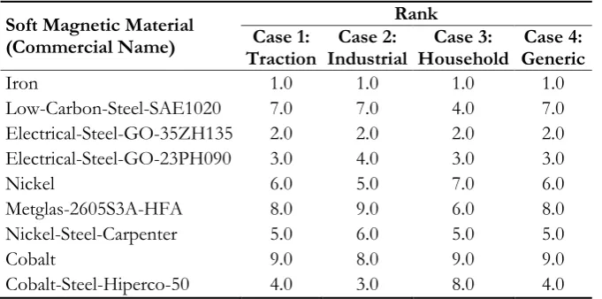
Table 7. Materials ranking through 2nd proposed method.
Soft Magnetic Material (Commercial Name)
Rank Case 1:
Traction Industrial Case 2: Household Case 3: Generic Case 4:
Iron 1.0 1.0 1.0 1.0
Low-Carbon-Steel-SAE1020 7.0 7.0 4.0 7.0 Electrical-Steel-GO-35ZH135 2.0 2.0 2.0 2.0 Electrical-Steel-GO-23PH090 3.0 4.0 3.0 3.0
Nickel 6.0 5.0 7.0 6.0
Metglas-2605S3A-HFA 8.0 9.0 6.0 8.0 Nickel-Steel-Carpenter 5.0 6.0 5.0 5.0
Cobalt 9.0 8.0 9.0 9.0
Cobalt-Steel-Hiperco-50 4.0 3.0 8.0 4.0
Table 6 and 7 show the materials results for these case studies. It can be seen that e.g. “Iron” and “Electrical-Steel-GO-35ZH135” are preferable alloys for any application, with the first one to perform better in most of the cases shown here. Although this is a quite expectable result, still the analysis followed have to be carefully considered if other quantities (like motor’s cogging torque or even other non-linear quantities such as the power losses are to be taken into account. Moreover, quite useful conclusions can be extracted about the suitability of these alloys for each application case examined. For example, “Cobalt-Steel-Hiperco-50” seems
to be more suitable for traction, industrial and general-purpose motors, while, its use is prohibitive for domestic applications, where the cost is of great concern. Similar observations can be particularly useful for the selection of the material in the preliminary stages of the design procedure.
4.
Overall Observations and Discussion
Many observations can be derived based on the previous results. For some of them a short analysis will be given here as an effort of understanding the materials influence on SCIM’s performance.
a) Between the first four materials (“Mu-Metal”, “Iron-Powder”, “Alloy-Core-Kool-mu-26”, “Magnetic-Ferrite-100C”) which are rejected at first place since they can’t produce the required SCIM’s output torque, there are two with “mu-metal” as basic constituent. These materials differ on the nickel, iron, chrome, copper and
molybdenum concentrations. The main reason, for which these materials are not suitable for a SCIM design, is the fact that they present “shield” behavior in static or low-frequency magnetic fields due to their high permeability. On the contrary, these materials are suitable and have already been applied e.g. in transformer protection from neighboring electromagnetic interference sources.
b) Continuing the above, the “Magnetic-Ferrite-100C” alloy consists of iron oxide (Fe2O3) in conjunction
with other metals. This material is electrically non-conductive and it can be easily magnetized. Actually, it
belongs to the “hard-ferrites” categories, which are hardly demagnetized in opposition to “soft-ferrites”.
While its applications can be i.e. loudspeaker magnets or small electric vehicle motors, it was found inappropriate for the stator/rotor core of a high efficiency SCIM, since it can’t produce enough torque (Table
4).
c) It can also be seen from Table 4 that another affecting factor for the material behavior relates to its
manufacturing process. This is clearly seen for materials “Iron”, “Casting-Cast-Iron”, and “Iron-Powder”.
Although they all originate from the same constituent, they exhibit different performance regarding the quantities under consideration. Specifically, while both of the first two satisfy the desired torque specification, the second performs poorly in terms of efficiency and power factor. At the same time, the third one performs poorly for any specification.
d) Continuing the observation of Table 4, another affecting factor is the material’s chemical composition.
[image:11.595.130.471.154.323.2]“Low-Carbon-Steel-SAE1020”. These alloys contain carbon in very low concentration (under 0.25%) which is denoted by the last two digits (i.e. “Steel 1010” contains 0.10% carbon). It seems that the alloy with the largest carbon
percentage in its composition, (“Low-Carbon-Steel-SAE1020”) exhibits the best performance in terms of efficiency and power factor.
e) It can be observed from Table 6 that some nickel and cobalt alloys which are commercially available
nowadays have by far better properties than conventional ones. This is apparent i.e. in the case of “Nickel-Steel-Carpenter”, which gathers a total of 19 points, while “Nickel” gathers a total of 24 points. However, the
cost of these improved new alloys is still significantly large compared to the cost of their conventional
candidates (for example the cost of “Cobalt” and “Cobalt-Steel-Hiperco-50” is practically inapplicable).
f) The steels “Electrical-Steel-NGO-35PN250”, 35ZH135” and “Electrical-Steel-GO-23PH090”, are alloys which contain silicon in a 6.5% concentration. They have some electrical engineering
applications since they exhibit certain magnetic properties like relatively small hysteresis region (Fig. 4) and low core losses. “NGO” in the first one’s name and “GO” in the other two alloy names stand for grain -oriented and non-grain--oriented respectively concerning their crystalline structure. This difference affects the electro-magnetic properties though. Consulting Table 4, it can be seen that if the designed SCIM has stator
and rotor cores from “GO” alloys exhibits higher efficiency (~8%) as well as higher power factor (~15.5%) comparing to the case where “NGO” alloy is used. Moreover, the total motor weight in “GO” case is less (~1kg) due to their lower mass density.
g) In case where the same alloy is used for the SCIM’s stator and rotor cores, the output torque, the
efficiency and the power factor values are larger than the corresponding ones of other combinations with different alloys (this has been observed in our analysis but is not shown here). It should be noted however, that there were very few cases where a very small (insignificant) improvement was noticed to the above quantities when different alloys were examined for the two cores.
h) Concerning the manufacturing cores’ cost, again when the same alloy is used for stator and rotor cores,
the cost is clearly less than any other combination of different alloys (not shown here). For example, in case
of “Electrical-Steel-GO-23PH090” there is a final cost of 11.68 USD, while the next cheaper combination is “Electrical-Steel-GO-23PH090” for stator, and “Iron” for rotor (12.20 USD), despite the fact that “Iron” is 10
times cheaper. The latter is explained by examination of the manufacturing process needed (from net material consumption cost to final lamination form cost) which is calculated automatically by the analysis software.
At the same time, the total motor’s weight remains smaller when the same material is used (the only exception
to that is the combination of “Electrical-Steel-GO23PH090” and “Electrical-Steel-GO-35ZH135” because of their
mass density which is the same).
i) In our example set of materials, by taking into account the ranking results presented in Table 6 and 7,
it could be said that “Iron”, “Electrical-Steel-GO-35ZH135” and “Electrical-Steel-GO-23PH090” are finally being accepted for a practical and efficient design. The careful selection of each quantity’s weight factor in each
different application and the analysis which has been carried out could provide valuable assistance to the designer (or manufacturer). The suitability of each alloy for a specific kind of application (i.e. industrial, traction, household or general-purpose motors) can be easily decided by the proposed ranking method.
Nevertheless, it has been clearly shown that the “suitability” of a commercially available soft magnetic
material for a modern and high efficiency induction motor should be examined thoroughly from many perspectives.
5.
Conclusion
References
[1] S. Manoharan, N. Devarajan, S. M. Deivasahayam, and G. Ranganathan, “Review on efficiency improvement in squirrel cage induction motor by using DCR technology,”Journal of Electrical Engineering, vol. 60, no. 4, pp. 227–236, 2009.
[2] P. Bertoldi and G. Kuehnemund, “The European negotiated agreement to improve motor efficiency,”
in Energy Efficiency Improvements in Electric Motors and Drives. P. Bertoldi, A. de Almeida, and H. Falkner, Eds. Springer, 2000, pp. 369-375.
[3] J. Malinowski, J. McCormick, and K. Dunn, “Advances in construction techniques of AC induction motors: Preparation of super-premium efficiency levels,”IEEE Transactions on Industry Application, vol. 40, no. 6, pp. 1665-1670, 2004.
[4] F. Parasiliti and M. Villani, “Technical and economical evaluation of electrical steels for high efficiency motors,”Transworld Research Network, Recent Res. Development Magnetics, no. 2, pp. 47-54, 2001.
[5] F. Parasiliti and M. Villani, “Design of high efficiency induction motors with die-casting copper rotors,”
in Energy Efficiency in Motor Driven Systems. F. Paraciliti and P. Bertoldi, Eds. Springer, 2003, pp. 144-151. [6] A. Stening and C. Sadarangani, “Starting performance of induction motors with cast aluminum and
copper rotors including the effects of saturation and inter-bar currents,”in Proc. of International Conference on Electrical Machines and Systems (ICEMS), Nov. 2009, Tokyo, Japan.
[7] A. K. Sawhney and A. Chakrabarti, Course in Electrical Machine Design, 6th ed. Delhi, India: Dhanpat Rai
& Sons, 2010.
[8] E. S. Hamdi, Design of Small Electrical Machines, 2nd ed. Wiley, 1998.
[9] J. Pyrhönen, T. Jokinen, and V. Hrabovcová, Design of Rotating Electrical Machines, 2nd ed. Wiley, 2014.
[10] C. Singh and D. Sarkar, “Practical considerations in the optimization of induction motor design,”Electric Power Applications, IEE Proceedings B, vol. 139, no. 4, 1992, pp. 365-373.
[11] H. Huang, E. F. Fuchs, and J. C. White, “Optimization of single phase induction motor design, Part II:
The maximum efficiency and minimum cost of an optimal design,” IEEE Transactions on Energy Conversion, vol. 3, no. 2, 1988, pp. 357-366.
[12] R. Ramarathnam and B. G. Desai, “Optimization of polysphase induction motor design: A nonlinear programming approach,” IEEE Transactions on Power Apparatus and Systems, vol. 90, no. 2, pp. 570-578, 1971.
[13] Y. D. Chun, P. W. Han, J. H. Choi, and D. H. Koo, “Multi-objective optimization of three-phase induction motor design based on genetic algorithm”, in Proc. of International Conference on Electrical Machines
(ICEM), Sept. 6-9, 2008, Vilamoura, Portugal.
[14] G. Liuzzi, S. Lucidi, F. Parasiliti, and M. Villani, “Multi-objective optimization techniques for the design of induction motors,” IEEE Transactions on Magnetics, vol. 39, no. 3, pp. 1261-1264, 2003.
[15] J. Besnerais, A. Fasquelle, V. Lanfranchi, M. Hecquet, and P. Brochet, “Mixed-variable optimal design of induction motors including efficiency, noise and thermal criteria,” in Proc. of 1st Intl. Conf. on Engineering
Optimization (EngOpt), Rio de Janeiro, Brazil, 1-5 June 2008, pp.1-10.
[16] E. Chiricozzi, F. Parasiliti, and M. Villani, “New materials and innovative technologies to improve the efficiency of three-phase induction motors, A case study,” in Proc. of the 16th Intl. Conf. on Electrical Machines
(ICEM), 5-8 Sep. 2004, Cracow, Poland.
[17] A. Krishnamoorthy and K. Dharmalingam, “Application of genetic algorithms in the design optima -zation of three phase induction motor,” Journal of Computer Applications, vol. 2, no.4, pp. 1-5, 2009. [18] L. Han, H. Li, J. Li, and J. Zhu, “Optimization for induction motor design by improved genetic
algorithm,” in Proc. of Australasian Universities Power Engineering Conference (AUPEC), 26-29 Sep. 2004, Brisbane, Australia.
[19] T. Hiyama, M. Ikeda, and T. Nakayama, “Artificial neural network based induction motor design,” in
Proc. of IEEE Power Engineering Society Winter Meeting, 2000, Singapore, pp. 264-268.
[20] MagWeb Co., Magnetic Material Database. [Online]. Available: http://magweb.us/bhmag-database-description/ [Accessed: Feb 16, 2016].
[22] M. Takashima, N. Morito, A. Honda, and C. Maeda, “Non oriented electrical steel sheet with low iron loss for high efficiency motor cores,” IEEE Transactions on Magnetics, vol. 35, no. 1, pp. 557-561, Aug. 2002.
[23] ANSYS Electromagnetic Suite (EM) v15: Maxwell 3D User’s Guide.
[24] W. R. Finley and M. M. Hodowanec, “Selection of copper versus aluminum rotors for induction motors,” IEEE Transactions on Industry Applications, vol. 37, no. 6, pp. 1563-1573, 2001.
[25] A. Asawachatroj, D. Banjerdpongchai, and P. Busaratragoon, “Enhancement of investment decision making using real options with application to advanced process control project,” Engineering Journal, vol. 18, no. 3, pp. 37-53, 2014
[26] M. Ehsani, Y. Gao, and S. Gay, “Characterization of electric motor drives for traction applications,” in
Proc. of 29th Annual Conf. of the IEEE Electronics Society (IECON' 03), Roanoke, VA, USA, Nov. 2-6, 2003, pp. 891-896.
[27] A. G. McCoy and J. G. Douglass, Premium Efficiency Motor Selection and Application Guide—A Handbook for Industry, U.S. Department of Energy's Office of Energy Efficiency and Renewable Energy, Washington D.C., 2014