Improving Thermal-Safe Test Scheduling for Core-Based
Systems-on-Chip Using Shift Frequency Scaling
Enkelejda Tafaj, Paul Rosinger, Bashir M. Al-Hashimi∗ University of Southampton
School of Electronics and Computer Science Southampton, SO17 1BJ, UK
{pmr,bmah}@ecs.soton.ac.uk
Krishnendu Chakrabarty
Department of Electrical and Computer Engineering Duke University
Durham, NC 27708 [email protected]
Abstract
Recently we have shown how hot-spots during test can be avoided without unnecessarily
increas-ing the testincreas-ing time by usincreas-ing a thermal-safe test schedulincreas-ing approach [15]. In this work, we
inves-tigate the impact of scan shift frequency scaling on the thermal-safe test scheduling performance
and propose an algorithm which embeds shift frequency scaling into the test scheduling process.
Experimental results show that this approach offers shorter overall testing times and significantly
improved ability of meeting tight thermal constraints when compared to existing thermal-safe test
scheduling approach based on a fixed scan shift frequency.
1: Introduction
Industrial experience shows that overheating due to rising levels of power consumption during
test poses several very serious challenges since both soft error rates and device aging increase
ex-ponentially with die temperature. An undesirable consequence of overheating is thermal stress. At
high temperatures, transistors fail to switch properly and many failure mechanisms, such as
electro-migration, are accelerated resulting in an overall decrease in reliability or even permanent damage.
These problems are exacerbated for core-based system-on-chip (SOC) designs because quite often,
∗
several embedded cores are concurrently tested at the system level to reduce test time.
Conse-quently, a significant amount of research has been devoted to reducing power consumption during
test in order to overcome these issues. Several solutions have been developed for test planning
dur-ing embedded core design, as well as durdur-ing chip-level system integration. Techniques falldur-ing in
the first category include low-power scan chain architectures with gated clocks [16, 4, 14], scan cell
and test pattern reordering [3, 5], and low-transition test patterns generated by specialized ATPG
algorithms [19] and low-transition TPGs [18]. The second category of techniques is mainly based
on power-constrained test scheduling algorithms [2, 8, 10, 7, 6, 1, 13, 11, 12] and the recently
proposed thermal-safe test scheduling algorithms [15]. Unlike power-constrained test scheduling
approaches, the thermal-safe test scheduling method we have presented in [15] guarantees
hot-spot-free test schedules by ensuring that a given critical die temperature is not exceeded during test. This
is possible by limiting the maximum test concurrency in each test session based on the thermal
behaviour of the cores under test rather than on their power consumption.
In this paper we use scan shift frequency scaling as a means of lowering die temperature and
investigate its impact on the thermsafe test scheduling process. In Section 2 we present an
al-gorithm which determines the appropriate scan shift frequency for each test session in order to
minimize the overall testing time and improve the ability to generating hot-spot free test schedules
under very tight thermal constraints. Scan shift frequency scaling also resolves eventual thermal
violations, issue which was not explicitly addressed in approach presented in [15]. An added
ad-vantage of this solution is that it does not require any modification of the embedded cores which
was indicated as a potential solution in [15]. The minor drawback of the proposed approach is that,
during test, the scan shift clock may need to be changed from one test session to another. The
experimental validation of the proposed approach is discussed in Section 3.
2: Thermal-safe test scheduling using scan shift frequency scaling
The mean time to failure (MTTF)—a commonly used metric in reliability models—is based
on the Arrhenius equation, which shows reliability is decreasing exponentially with the absolute
junction temperature: M T T F = AeEakT, where A is an empirical constant, Ea is the so-called
activation energy and k is Boltzmann’s constant [17]. The semiconductor industry is currently
using commonly accepted for the maximum operating junction temperature based on the device
package type. These have been well accepted as numbers relating to reasonable device lifetimes
allowable junction temperature is 150°C, while for devices assembled in ceramic or cavity DIP
packages, the maximum allowable junction temperature is 175°C [9]. Based on these practices, the
thermal-safe test scheduling approach proposed in this paper aims to produce solutions ensuring
that the maximum allowable junction temperature will not be exceeded during test. Throughout
this paper, the term “hot-spot” will be used to refer to cores that exceed the maximum allowable
junction temperature during test. Any tests running below this critical temperature are considered
to be “thermally safe”.
According to the well known electro-thermal duality, there is a linear relationship between the die
temperature(T) and the power consumption(P) [17]. Since dynamic power consumption is directly
proportional with the clock frequency, it can be concluded that there is a linear dependency between
the die temperature and the operating clock frequency. In scan based test, the shift cycles dominate
the testing time, and consequently the thermal behaviour of the silicon die during test. In this work
we are exploiting the above observations and the fact that the scan shift frequency can be changed
without affecting the quality of the test, in order to use scan shift frequency scaling as a method
of lowering the die temperature during test. The cost paid for the lower die temperature obtained
by scaling down the scan shift frequency is having longer test times, for example halving the shift
frequency will double the test length.
The proposed test scheduling algorithm is shown in Figure 1. The algorithm starts from the
set of cores (S) of the target system, the corresponding test compatibility graph (TCG) and the
maximum junction temperature that can be tolerated during test (Tmax). Each core is annotated
with the length of its corresponding test for a given default scan shift frequency (F reqinit). The
TCG captures the concurrency compatibility relationships between the system cores: each node in
the TCG corresponds to a core, and an edge between two nodes means that the two corresponding
cores can be tested concurrently without causing any resource conflicts. The algorithm returns
a thermal-safe test schedule as a list of test sessions and their corresponding scaling factors for
the scan shift frequency. Each test session in the test schedule is a group of cores to be tested
concurrently. It is assumed that all cores tested in the same test session share the same scan shift
clock, but this can vary from one test session to another.
The algorithm starts by computing all the cliques of the TCG and the clique with the longest test
length if its cores are tested sequentially is selected. Then the corresponding cores are assigned to
a test session TS (lines 4-8). Next, the scan shift frequency for TS (F reqT S) is set to the default
INPUT: S, the core set for the target system
Tmax= maximum tolerable temperature F reqinit= initial test clock frequency
OUTPUT: Thermal-safe schedule as a list of
thermal-safe test sessions
and their corresponding shift frequenciesF reqT S
1 Available ={Ci|Ci∈S}
2 Hsol =∅
3 while Available6=∅do
4 TS =∅
5 TCG = test compatibility graph (Available) 6 TCC = all cliques( TCG )
7 Cliquemaxlength= Clique in TCC with maximal test length 8 addCores(Cliquemaxlength) to TS
9 F reqT S=F reqinit
10 thermal simulation(TS,F reqinit)
11 if MaxTemp(TS)> Tmax
12 F reqT S= scale frequency(TS, MaxTemp(TS)),Tmax
13 endif
14 foreachC∈TS do
15 remove C from Available 16 endfor
17 add (TS,F reqT S) to Hsol
18 endwhile
19 Hsol holds the thermal-safe test schedule
Figure 1. Proposed thermal-safe test scheduling algorithm
the maximum die temperature during test MaxTemp(TS) for this particular test session (lines
9-10). In case the maximum die temperature reached during TS exceeds the maximum tolerable
temperatureTmax, the scan shift frequency of the test session is scaled down until MaxTemp(TS) is
brought under the thermal constraintTmax(lines 11-13). The shift frequency scaling is performed
using a binary search-like iterative procedure in order to ensure the final MaxTemp(TS) is within
a specified temperature interval fromTmax. In our experiments we have used a value of 0.5 °C
for this. It is important to keep MaxTemp(TS) close toTmaxbecause lowering it further than that
will not improve the thermal-safety of the test session but it will unnecessarily extend its length.
Some experimental results on how the value of the temperature interval fromTmax effect the test
schedule length and the simulation effort are shown in Section 3. Once the scaled shift frequency
(F reqT S) has been computed, the pair (TS,F reqT S) is added to the test schedule (Hsol) and the
corresponding cores are removed from the list of the available cores (lines 14-17). The algorithm
reiterates the steps described above on the list of available cores until all cores have been assigned
3: Experimental results
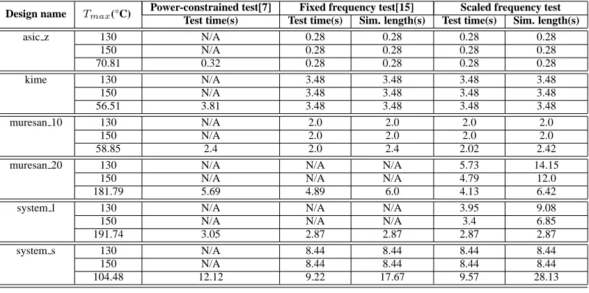
Table 1 compares the performance of the proposed algorithm (columns 6-7) with the power
con-strained test scheduling approach presented in [7](column 3) and the thermal-safe test scheduling
approach with fixed scan shift frequency presented in [15](columns 4-5). In our experiments, we
have used the benchmark designs from [7]. Details such as physical layout dimensions and
real-istic test power and time values needed to be added to the original design descriptions in order to
provide all necessary information for the proposed thermal safe test scheduling algorithm. Thermal
simulations were performed using the HotSpot tool [17].
The performance of the test scheduling algorithms is compared in terms of test schedule length
(columns 3, 4 and 6), and thermal simulation effort (columns 5 and 7). The second column shows
the thermal constraintTmaxused in each experiment. For each design, three values ofTmax were
used: 130 °C, 150 °C and the maximum temperature corresponding to the test schedule obtained
using the power constrained test scheduler that was presented in [7]. The cases where a test schedule
could not be generated for the given thermal constraint because of thermal violations are marked
with N/A. As it can be seen, the proposed solution is able to compute a thermal safe test schedule for
all designs and thermal constraints considered. For example, for the circuit muresan 20, both power
constrained test scheduling from [7] and the thermal-safe test scheduling approach from [15] fail
to meet the thermal constraints of 130 °C and 150 °C because the die temperature of certain cores
exceeds these value for the default scan shift frequency even when tested in a purely sequential test
schedule. Moreover, even in some cases where the first two approaches can compute a
thermal-safe solution, the proposed approach generates a shorter test schedule. For example, for the design
muresan 20, the test schedule generated using the proposed approach is only 4.13 seconds long,
when compared with the 5.69 seconds test schedule generated using the power constrained approach
presented in [7] and the 4.89 seconds test schedule computed using the thermal-safe test scheduling
approach presented in [15]. This is because, in some cases, the overall testing time gains due
to the increased test concurrency per test session obtained by scaling down the shift frequency
exceed the increase in test session length due to scaling. The downside of the proposed solution
is the increased thermal simulation effort. For example for system s, for a thermal constraint of
104.48 °C, the thermal simulation length required by the proposed approach is over 28 seconds,
when compared to less than 18 seconds required by the approach presented in [15].
The number of test sessions which requre scaling down of the scan shift frequency increases as
Design name Tmax(°C) Power-constrained test[7] Fixed frequency test[15] Scaled frequency test Test time(s) Test time(s) Sim. length(s) Test time(s) Sim. length(s)
asic z 130 N/A 0.28 0.28 0.28 0.28
150 N/A 0.28 0.28 0.28 0.28
70.81 0.32 0.28 0.28 0.28 0.28
kime 130 N/A 3.48 3.48 3.48 3.48
150 N/A 3.48 3.48 3.48 3.48
56.51 3.81 3.48 3.48 3.48 3.48
muresan 10 130 N/A 2.0 2.0 2.0 2.0
150 N/A 2.0 2.0 2.0 2.0
58.85 2.4 2.0 2.4 2.02 2.42
muresan 20 130 N/A N/A N/A 5.73 14.15
150 N/A N/A N/A 4.79 12.0
181.79 5.69 4.89 6.0 4.13 6.42
system l 130 N/A N/A N/A 3.95 9.08
150 N/A N/A N/A 3.4 6.85
191.74 3.05 2.87 2.87 2.87 2.87
system s 130 N/A 8.44 8.44 8.44 8.44
150 N/A 8.44 8.44 8.44 8.44
[image:6.595.88.511.114.325.2]104.48 12.12 9.22 17.67 9.57 28.13
Table 1. Test scheduling performance comparison
thermal constraintTmax is shown in column 2. Column 3 shows the cores that were assigned to
each test session by the proposed algorithm shown in Figure 1. The maximum temperatures and
the shift frequency scaling factors for each test session are shown in columns 4 and 5 respectively.
In the last column of Table 2 shows the overal test times for each test schedule. In order to meet the
thermal constraint of 181.79 °C the default scan shift frequency had to be scaled down by the factor
0.96 for the first test session TS1 as shown in the table. The other test sessions can be run without
changing the default scan shift frequency for thisTmax. For a very tight thermal constraint, such
as 130 °C the default frequency needs to be scaled down for 4 out of 5 test sessions. This explains
also the increase in the overall test time from 4.13 seconds corresponfing toTmax=181.79 °C to
5.73 seconds forTmax=130 °C.
Design name Tmax(°C) Test Session MaxTemp(TS)(°C) Scaling factor Test time
muresan 20 181.79 TS1: [b12, b3, b2, b5] 181.79 0.96 4.13 TS2: [b17, b1, b4, b9, b15] 167.96 1.0
TS3: [b6, b14, b7, b20] 85.62 1.0 TS4: [b11, b8, b16, b10] 136.46 1.0 TS5: [b13, b18, b19] 159.76 1.0
muresan 20 150 TS1: [b12, b3, b2, b5] 149.81 0.73 4.79 TS2: [b17, b1, b4, b9, b15] 149.97 0.85
TS3: [b6, b14, b7, b20] 85.62 1.0 TS4: [b11, b8, b16, b10] 136.46 1.0 TS5: [b13, b18, b19] 149.54 0.83
muresan 20 130 TS1: [b12, b3, b2, b5] 129.90 0.58 5.73 TS2: [b17, b1, b4, b9, b15] 129.99 0.69
TS3: [b6, b14, b7, b20] 85.62 1.0 TS4: [b11, b8, b16, b10] 129.91 0.92 TS5: [b13, b18, b19] 129.88 0.59
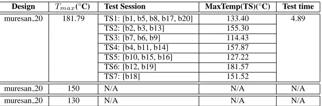
[image:6.595.106.491.553.719.2]For comparison the simulation results obtained by using the thermal-safe test scheduling method
we presented in [15] for the same design (column 1) and the same thermal constraints (column 2)
as in Table 2 are shown in Table 3. In columns 3 and 4 the test sessions with the corresponding
temperature values generated by the test scheduling method presented in [15] are shown. As shown
in Table 2 7 test sessions are generated using this method. The thermal constraint of 181.79 °C
computed by using the power values for each core can be met. The test time of 4.89 seconds is
longer then 4.13 seconds obtained by scaling the shift frequency as in the proposed approach (see
Table 2) because of a lower concurrency. The tight thermal constraint of 150 °C and 130 °C can not
be met because the die temperature of certain cores, for example of core B18, exceed the thermal
constraint even when tested sequentially.
Design Tmax(°C) Test Session MaxTemp(TS)(°C) Test time
muresan 20 181.79 TS1: [b1, b5, b8, b17, b20] 133.40 4.89 TS2: [b2, b3, b13] 155.30
TS3: [b7, b6, b9] 114.43 TS4: [b4, b11, b14] 157.87 TS5: [b10, b15, b16] 127.22 TS6: [b12, b19] 181.57 TS7: [b18] 151.52
muresan 20 150 N/A N/A N/A
[image:7.595.142.458.315.419.2]muresan 20 130 N/A N/A N/A
Table 3. Thermal-safe test schedule with fixed shift frequency for muresan 20
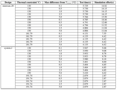
Table 4 reports a more detailed set of simulation results for the designs muresan 20 and system l.
For each design (column 1) and thermal constraint (column 2), different values for the allowed
dif-ference between the thermal contraintTmaxand the final maximal temperature for each test session
MaxTemp(TS) (see Figure 1) were chosen (column 3). The test time and the thermal simulation
effort are shown in the columns 4 and 5. Keeping MaxTemp(TS) very close to a given thermal
con-straintTmaxwill avoid unnecessarily scaling down the shift frequency, and thus increasing the test
schedule length. On the other hand, as mentioned in Section 2, the shift frequency scaling is
per-formed by using a binary-search like iterative procedure. Consequently, a longer search increases
the thermal simulation effort. For example, for the design muresan 20 and a thermal constraint
ofTmax=150 °C, when the maximum difference fromTmax is set 0.1 °C the test schedule length
is 4.785 seconds. The simulation effort in this case is 14.46 seconds. Increasing the temperature
interval fromTmaxfrom 0.1 °C to 5.0 °C leads to a 4% increase of the test schedule length (from
4.785 seconds to 4.806 seconds), while the thermal simulation effort decreases from 14.46 seconds
Design Thermal constraint(°C) Max difference fromTmax(°C) Test time(s) Simulation effort(s)
muresan 20 130 0.1 5.729 14.82
130 0.5 5.730 14.15
130 1.0 5.730 14.15
130 2.5 5.730 14.15
130 5.0 5.766 13.50
150 0.1 4.785 14.46
150 0.5 4.791 12.00
150 1.0 4.796 11.52
150 2.5 4.806 11.04
150 5.0 4.806 11.04
181.79 0.1 4.131 7.55
181.79 0.5 4.135 6.42
181.79 1.0 4.135 6.42
181.79 2.5 4.135 6.42
181.79 5.0 4.135 6.42
system l 130 0.1 3.947 9.68
130 0.5 3.950 9.08
130 1.0 3.953 8.78
130 2.5 3.953 8.78
130 5.0 3.980 8.18
150 0.1 3.401 8.00
150 0.5 3.404 6.85
150 1.0 3.404 6.85
150 2.5 3.404 6.85
150 5.0 3.410 6.62
191.74 0.1 2.879 2.87
191.74 0.5 2.879 2.87
191.74 1.0 2.879 2.87
191.74 2.5 2.879 2.87
[image:8.595.98.500.111.419.2]191.74 5.0 2.879 2.87
Table 4. Correlation between the difference between the given thermal constraint and the maximum temperature for a test session, test time and simulation effort
4: Conclusions
Overheating has been acknowledged as a major problem during the testing of complex
system-on-chip (SOC) integrated circuits. In [15] we had outlined the need for thermal-safe testing and
explained why existing power-constrained test scheduling approaches cannot guarantee thermal
safety during test. In this paper we have investigated the impact of scan shift frequency scaling on
the thermal-safe test scheduling process and we have presented a novel thermal-safe test scheduling
algorithm which determines the appropriate scan shift frequency for each test session in order to
reduce the overall testing time and solve eventual thermal violations. Experimental results show
that the proposed approach can lead to shorter test schedules and is capable of handling very tight
thermal constraints when compared to the earlier work on thermal-safe test scheduling presented in
[15]. We believe the proposed approach provides an effective solution to the problem of hot-spots
References
[1] K. Chakrabarty. Design of system-on-a-chip test access architectures under place-and-route and power constraints. In Proc. IEEE/ACM Design Automation Conference (DAC), pages 432–437, 2000. [2] R. Chou, K. Saluja, and V. Agrawal. Scheduling tests for VLSI systems under power constraints. IEEE
Transactions on Very Large Scale Integration (VLSI) Systems, 5(2):175–184, June 1997.
[3] P. Flores, J. Costa, H. Neto, J. Monteiro, and J. Marques-Silva. Assignment and reordering of in-completely specified pattern sequences targeting minimum power dissipation. In 12th International Conference on VLSI Design, pages 37–41, 1999.
[4] P. Girard, L. Guiller, C. Landrault, S. Pravossoudovitch, and H. J. Wunderlich. A modified clock scheme for a low power. In Tech. report, 2001.
[5] P. Girard, C. Landrault, S. Pravossoudovitch, and D. Severac. Reducing power consumption during test application by test vector ordering. In Proc. International Symposium on Circuits and Systems (ISCAS), pages 296–299, 1998.
[6] V. Iyengar and K. Chakrabarty. System-on-a-chip test with precedence relationships, preemption and power constraints. IEEE Transactions on Computer-Aided Design of Integrated Circuits and Systems, 21:1088–1094, September 2002.
[7] E. Larsson, K. Arvidsson, H. Fujiwara, and Z. Peng. Efficient test solutions for core-based designs. IEEE Transactions on Computer-Aided Design of Integrated Circuits and Systems, 23(5):758–775, May 2004.
[8] V. Muresan, X. Wang, V. Muresan, and M. Vladutiu. A comparison of classical scheduling approaches in power-constrained block-test scheduling. In Proc. IEEE International Test Conference (ITC 2000), pages 882–891, 2000.
[9] National Semiconductor. Understanding Integrated Circuit Package Power Capabilities, April 2000. http://www.national.com/ms/UN/UNDERSTANDING INTERGRATED CIRCUIT PACKAGE POWER CA.pdf.
[10] N. Nicolici and B. Al-Hashimi. Power conscious test synthesis and scheduling for BIST RTL data paths. In Proc. IEEE International Test Conference (ITC 2000), 2000.
[11] M. Nourani and J. Chin. Power-time trade off in test scheduling for SoCs. In Proc. IEEE International Conference on Computer Design(ICCD), 2003.
[12] M. Nourani and J. Chin. Test scheduling with power-time tradeoff and hot-spot avoidance using MILP. IEE Proceedings - Computers and Digital Techniques, 151(5):341–355, September 2004.
[13] C. P. Ravikumar, G. Chandra, and A. Verma. Simultaneous module selection and scheduling for power-constrained testing of core based systems. In 13th International Conference on VLSI Design, pages 462–467, 2000.
[14] P. Rosinger, B. Al-Hashimi, and N. Nicolici. Scan architecture with mutually exclusive scan segment activation for shift and capture power reduction. IEEE Transactions on Computer Aided Design of Integrated Circuits, pages 1142–1154, 2004.
[15] P. Rosinger and B. M. Al-Hashimi. Rapid generation of thermal-safe test schedules. In Design Au-tomation and Test Europe (DATE), 2005.
[16] J. Saxena, K. M. Butler, and L. Whetsel. An analysis of power reduction techniques in scan testing. In IEEE International Test Conference(ITC), pages 670–677, 2001.
[17] K. Skadron, M. Stan, W. Huang, S. Velusamy, K. Sankaranarayanan, and D. Tarjan. Temperature-aware microarchitecture. In International Symposium on Computer Architecture (ISCA), pages 2–13, 2003. [18] S. Wang and S. K. Gupta. DS-LFSR: A new BIST TPG for low heat dissipation. In Proc. IEEE
International Test Conference, pages 848–857, 1997.