Quasi Two-Level PWM Operation of a Nine-Arm
Modular Multilevel Converter for Six-Phase
Medium-Voltage Motor Drives
Mohamed S. Diab, Grain P. Adam, B. W. Williams Electronic and Electrical Engineering Dept.
University of Strathclyde Glasgow, U.K.
Ahmed M. Massoud Electrical Engineering Dept.
Qatar University Doha, Qatar
Shehab Ahmed ECENDept.
Texas A&M University at Qatar Doha, Qatar
Abstract—This paper proposes a hybrid converter for medium-voltage six-phase machine drive systems that mixes the operation of a traditional two-level voltage-source inverter and the modular multilevel converter (MMC) to enable operation over a wide frequency range. Topologically, the proposed converter consists of nine arms resembling two sets of three-phase MMCs with three common arms, yielding a nine-arm MMC with a 25% reduction in the number of employed arms compared to a traditional dual three-phase MMC. The multilevel property of a standard MMC is emulated in the proposed converter, however on a two-level basis, resulting in a stepped two-level output voltage waveform. The proposed converter has a reduced footprint with advantages of small voltage steps, modular structure, and ease of scalability. Further, it is able to drive high-power six-phase machines within low operating frequencies at the rated torque. The operating principle of the converter is elaborated, and its modulation scheme is discussed. The features of the proposed converter are verified through simulations and experimentally.
Index Terms—Medium-voltage drives, modular multilevel converter (MMC), nine-arm MMC, six-phase machines, sub-module (SM) capacitor voltage ripple, quasi two-level PWM.
I. INTRODUCTION
Over the past decades, adjustable speed drives have gained research attention due to their key role in industrial, commercial, and military applications. With the wide deployment of high power applications in various sectors, such as ship propulsion, milling rolls, and oil and gas applications, the power level requirement of the adjustable speed drives is invariably increasing, reaching the megawatt level, where medium voltage (MV) grids are inevitably utilized as the main power source [1]. As a result, the MV high-power drives have triggered the development of MV converter topologies, while fostering multiphase machine rejuvenation based on its salient feature of reducing the rated current of the semiconductor devices, compared to three-phase machines at the same power level.
Multiphase drives incorporating six-phase machines have garnered most of the interests among the numerous multiphase possibilities due to their modular three-phase structure which allows adaptation of existing three-phase technology. Compared to conventional three-phase machines, six-phase machines provide lower ripple in both developed torque and dc-link current harmonics, higher efficiency, and improved system
reliability [2], [3]. In the recent literature, six-phase machines have been addressed from different perspectives, considering their design [4], control [5], [6], and applications [7], [8]. Six-phase machines are fundamentally supplied from a dual three-phase voltage-source inverter (VSI) comprising six phase-legs. Nonetheless, multilevel converter topologies are much preferred as motor drives in MV applications, being able to provide a stepped output voltage waveform that reduces
𝑑𝑣/𝑑𝑡 stresses on the motor terminals. With the shortcomings of the state-of-the-art multilevel converter topologies [9]-[11], the modular multilevel converter (MMC) has established itself as a mature technology with prominent advantages that enabled it to be a standard converter interface in the high-voltage direct-current transmission field [12], while promoting it as a promising candidate for MV machine drives [13]. Since three-phase MMC topologies can be typically extended to supply six-phase machines, six-six-phase MMC configurations are not frequently reported in literature [14].
One major drawback of the MMC topology is the wide energy variation at the sub-module (SM) capacitor, which increases with reduced operating frequency and determines the sizing requirement of SM capacitance. This inherent constraint precludes the MMC from many MV drives applications where startup from stand-still and continuous low-speed operation are required. With the SM capacitance being the dominant factor for both cost and volume of the MMC, feeding an MV six-phase machine through a traditional six-phase MMC, while Volt/Hertz control is a prime requirement, will not be technically attractive nor cost effective. In this context, this paper presents a drive system configuration for MV six-phase machines, which compromises the prominent attributes of the MMC topology to offer a six-phase motor drive system with significantly diminished SM capacitance and reduced silicon area. The drive system is recognized as an MMC-based configuration that employs three phase-legs comprising nine arms, with the capability of generating two independent sets of three-phase voltages. The nine-arm MMC topology is operated using a quasi-two-level (Q2L) pulse-width modulation (PWM) approach which significantly reduces the SM capacitance requirement.
modulation as introduced in literature. Section III illustrates the Q2L PWM as a proposed modulation scheme for the nine-arm MMC. Verification results from simulation models and downscaled experimentation are presented in Section IV. An assessment of the proposed approach, highlighting its pros and cons, is given in Section V. Section VI concludes the paper.
II. NINE-ARM MMC WITH STANDARD MODULATION
A. Structure
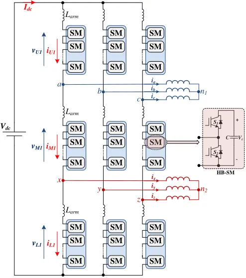
The nine-arm MMC was first introduced in [15], where it is structurally similar to the nine-switch converter (NSC). The NSC consists of three legs with two sets of three-phase interfacing terminals. Each leg is composed of upper, middle, and lower switches, where it can be seen as the merging of two three-phase VSIs with dual-function middle switches [16]. Intrinsically, the NSC was introduced to independently control two three-phase motors [17], while recently has been employed to empower six-phase machines [7]. That is, the nine-arm MMC consists of three legs each with three installed arms, namely upper, middle, and lower arms. Similar to a conventional MMC, each arm consists of N series-connected SMs. Each SM can be a half-bridge (HB) or a full-bridge (FB) cell with a dc capacitor of a capacitance C, while the SM capacitor and switching devices are rated for 𝑉𝑐. A circuit diagram for a nine-arm MMC,
with HB-SMs, feeding a six-phase machine with isolated neutral points is shown in Fig. 1.
B. Principles of Standard Modulation
Since the nine-arm MMC generates two different sets of three-phase voltages, the modulating signals of both upper and lower arms are independent. Referring to Fig. 1, a general form for the two three-phase voltage sets are:
𝑣𝑗𝑛1= 𝑉𝑜sin (𝜔𝑡 − 2𝜋
3 𝑘) , 𝑘 = 0, 1, 2 𝑓𝑜𝑟 𝑗 = 𝑎, 𝑏, 𝑐 (1a)
𝑣𝑗𝑛2= 𝑉𝑜sin (𝜔𝑡 −2𝜋
3 𝑘 + 𝜑) , 𝑘 = 0, 1, 2 𝑓𝑜𝑟 𝑗 = 𝑥, 𝑦, 𝑧 (1b)
where 𝜔 is the output angular frequency, 𝜑 is the phase angle between the two voltage sets, and 𝑉𝑜 is the magnitude of the
output phase-voltage, and is defined by the modulation index 𝑀
and the input dc voltage 𝑉𝑑𝑐 as follows.
𝑉𝑜= 1
3 𝑀 𝑉𝑑𝑐 (2)
The arm reduction achieved in the nine-arm MMC topology imposes an operational limit in the dc-link voltage utilization due to the dual functionality of the middle arms, where it is reduced by 33%. To achieve the same power rating as a traditional dual three-phase MMC, the dc-link voltage of the nine-arm MMC must be increased by 50%.
In standard modulation of nine-arm MMC [15], each arm is controlled to generate a sinusoidal voltage ranging from 0 to
𝑉𝑑𝑐. Referring to Fig. 1, and considering the MMC phase-leg
[image:2.612.318.565.51.330.2]supplying machine terminals 𝑎 and 𝑥 (denoted as leg-1), the reference voltages for both upper and lower arms are given as shown in (3), where the subscripts U, M, and L are utilized to refer to the corresponding ‘upper’, ‘middle’, and ‘lower’ arm, respectively.
Fig. 1 Nine-arm MMC feeding a six-phase machine with isolated neutral points.
(a) (b)
Fig. 2 Stator winding diagram of six-phase machines for (a) asymmetrical machine and (b) symmetrical machine.
𝑣𝑈1= 1
3𝑉𝑑𝑐[1 − 𝑀 sin(𝜔𝑡)] (3a)
𝑣𝐿1= 1
3 𝑉𝑑𝑐[1 + 𝑀 sin(𝜔𝑡 + 𝜑)] (3b)
The reference voltages of both upper and lower arms are utilized to determine the number of SMs to be inserted/bypassed through a triangular carrier signal comparison. The middle arm is modulated in a scheme that ensures a zero voltage sum in the loops incorporating the MMC phase-legs and the dc-link. That is, the modulation of the middle arm depends on the phase angle between the two generated three-phase voltage sets, as given by (4).
𝑣𝑀1= 𝑉𝑑𝑐
3 [1 + 𝑀 sin(𝜔𝑡) − 𝑀 sin(𝜔𝑡 + 𝜑)] (4)
With the phase angle 𝜑 greater than 60⁰, the middle-arm voltage ranges from −𝑉𝑑𝑐⁄3 to 𝑉𝑑𝑐, where such bipolar voltage
can be realized by the incorporation of FB-SMs in the middle arms of the converter. However, since the spatial winding connection of both asymmetrical and symmetrical six-phase
a SM SM SM Larm SM SM SM SM SM SM b c n1 x y z n2 Vdc ia ib ic ix iy iz SM SM SM SM SM SM SM SM SM SM SM SM SM SM SM SM SM SM C + -Vc HB-SM Larm Larm iU1 vU1 iM1 vM1 iL1 vL1 Idc S1 S2 a b c z y n1 n2 x 30° 120° 60° 120° a b c x z
machines, shown in Fig. 2, implies 30⁰ and 60⁰ as a phase shift between the voltage vectors of the two sets of three-phase stator voltages, respectively, the nine-arm MMC can drive both types of six-phase machines with an identical HB-SMs structure for the upper, middle, and lower arms.
C. Low-Frequency Operation
The nine-arm MMC topology inherits the serious challenge of conventional MMC configuration when operating at low frequencies and high currents as a primarily requirement of high-power adjustable-speed drives. With fundamental and second-order ripple powers pulsating simultaneously in MMC arms [13], the SM capacitors experience wide voltage fluctuations, especially at low operating frequencies, that could threat the safety of switching devices and adversely affect the MMC normal operation. To maintain SM capacitor voltage-ripple within tolerated values, the SM capacitance should be designed fairly large to compensate for the high voltage-ripple, which increases the converter volume and weight, while increasing the system stored energy. Nonetheless, at near zero frequency, the SM capacitor voltage exhibits a unidirectional change with an extreme voltage-ripple, where increasing the SM capacitance is no longer valuable.
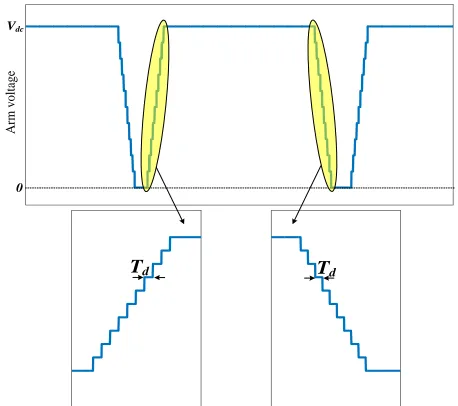
III. Q2L PWM OPERATION OF THE NINE-ARM MMC This paper suggests the nine-arm MMC be operated in a Q2L PWM mode as a trade-off approach that can limit SM capacitor voltage fluctuation with reduced SM capacitance and semiconductor silicon area. Originally, the Q2L approach was proposed in [18] for MMCs utilized in dc-dc transformer applications to mimic the VSI operation using an MMC structure, with the goal of minimizing the SM capacitance. Thereafter, the Q2L operation was combined with a triangular-carrier-based PWM scheme for MMC-fed drives application [19]. In this operation mode, the MMC generates PWM voltages with a controllable 𝑑𝑣 𝑑𝑡⁄ by briefly employing the SM capacitors to synthesis intermediate voltage steps between the two dominant voltage levels of the ac output voltage. That is, the SM capacitors are switched on/off in a delayed manner relative to each other, such that both rising and falling rates of the generated voltage are realized through a staircase waveform as shown by the idealized sketch in Fig. 3. The time spent at each intermediate voltage level is denoted as the dwell time, 𝑇𝑑,
which is selected small enough to reduce the energy storage requirement per SM capacitance for a given voltage-ripple. Therefore, the inrush current due to imbalance between the dc-link voltage and the sum of voltages across SM capacitors will be considerably limited, resulting in a diminished arm inductance requirement which can be realized through parasitic inductance of connection paths.
The operational characteristics of the nine-arm MMC topology under Q2L PWM is similar to that of the NSC, where the utilization of the dc-link voltage depends on the phase angle between both modulation signals of upper and lower arms. That is, the maximum allowable modulation index when driving a six-phase machine depends on whether the machine has a symmetrical or asymmetrical winding connection, as defined by (5) [20].
𝑀 ≤ 1
1 + sin (𝜑2) (5)
With 30⁰ and 60⁰ displacement angles of asymmetrical and symmetrical six-phase machines, respectively, the modulation index will be limited to 0.794 and 0.667 respectively, which necessitates increasing the dc-link voltage by 20% and 33% respectively, to guarantee the same power level compared to a traditional dual three-phase MMC.
The valid states for each phase leg of the nine-arm MMC are described as follows.
1) State {1}: Both phases from the same leg are tied to the positive dc pole.
2) State {0}: One phase is tied to the positive dc pole, while the other phase within the same leg is tied to the negative dc pole.
3) State {−1}: Both phases from the same leg are tied to the negative dc pole.
[image:3.612.323.552.302.505.2]In each of the above switching states, only one arm has all of its SM capacitors inserted, while the other two arms of the same leg will have all SM capacitors bypassed.
Fig. 3 Q2L approximation within two PWM switching cycles.
Fig. 4 Reference and triangular signals for Q2L PWM operation of nine-arm MMC (𝑀 = 0.794 and 𝜑 = 30⁰).
0 Vdc
A
rm
v
o
lt
ag
e
Td
Td
[image:3.612.328.546.537.697.2]Fig. 5 Q2L PWM scheme of one phase-leg of the nine-arm MMC.
The Q2L PWM approach of the nine-arm MMC implies the upper reference voltages always be placed above the lower reference ones, without crossover intersection. This can be guaranteed by adding a voltage offset, 𝑣𝑜𝑓𝑓𝑠𝑒𝑡, to both reference
voltage sets, which depends on the winding connection of the six-phase machine, and is set to 0.2 pu and 0.33 pu for asymmetrical and symmetrical machines, respectively. The reference voltages are then compared with a bipolar carrier signal to generate the PWM switching schemes for both upper and lower arms, as shown in Fig. 4, where they are fed into an XOR logical operator to generate the PWM switching scheme of the middle arm. With the information of the employed number of SMs per arm in addition to the dwell time, the PWM switching scheme is converted into Q2L PWM commands that determine the number of SMs to be inserted/bypassed. The SM capacitor voltage balancing is maintained by a selection mechanism based on capacitor voltage measurements at each switching instance. This mechanism sorts the SM capacitor voltages and then decides which specific SM to be inserted or bypassed, according to the relative arm current direction [21]. Accordingly, the firing signals of individual SMs are generated, as shown in the block diagram of Fig. 5, where 𝑣𝑎∗ and 𝑣𝑥∗ are
the normalized signals of the output voltages given by (1a) and (1b) respectively at 𝑘 = 0.
IV. VERIFICATION
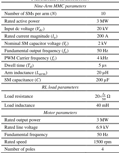
The performance of the nine-arm MMC topology under Q2L PWM is investigated through both simulation and experimentation. A 3 MW MATLAB/SIMULINK model is used to investigate both steady-state and transient performance, while a 3 kW laboratory prototype is tested with an RL passive load. Parameters for simulation and experiment are listed in Table I and II, respectively.
A. Simulation Results
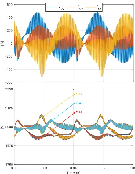
Figs. 6 and 7 show the fundamental waveforms of a 3 MW nine-arm MMC operating at 50 Hz under Q2L PWM scheme, while feeding two sets of three-phase RL loads. The angle between the two three-phase voltage sets is 30⁰. Two line-voltage samples, each from one three-phase set, are shown in Fig. 6a with an expanded view in Fig. 6b, where they range from the negative dc pole to the positive one in a Q2L PMW fashion. Six-phase load currents are shown in Fig. 6c with a high-quality sinusoidal waveform and a THD of 3.3%. The supply current is shown in Fig. 6d, and has a pulsating waveform that is near unipolar. The arm currents and SM
capacitor voltages of leg-1 are shown in Fig. 7. Both upper and lower arm currents are pulsating within the envelope waveform of the sum of 𝑖𝑎 and 𝑖𝑥, in a complementary manner. Whereas,
the middle arm current pulsates between the envelopes of −𝑖𝑎
and 𝑖𝑥. The SM capacitor voltages are balanced around their
nominal value. The capacitor voltage-ripple is recorded as
±4.25%, ±2.25%, and ±3.5% for SMs in upper, middle, and lower arms, respectively, using 200 µF SM capacitance. The voltage-ripple profile of middle arm SMs is lower than that of both the upper and lower arm SMs due to the different current conduction of the arms.
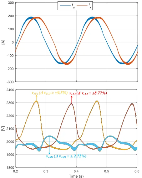
Figs. 8 and 9 show the steady-state performance of the nine-arm MMC at 10 Hz and 5 Hz, respectively. The output voltage is reduced in accordance to the operating frequency reduction, while the load resistance is varied linearly with the operating frequency to maintain the output current constant at the rated value to emulate the constant torque characteristic of variable-speed machines. In both figures, the load currents 𝑖𝑎and𝑖𝑥are
shown together with a 30⁰ phase displacement, while SM capacitor voltages for different arms are also shown. Capacitor voltage ripple for SMs in upper arm is shown to be ±8%
TABLEI PARAMETERS FOR SIMULATION
Nine-Arm MMC parameters
Number of SMs per arm (N) 10
Rated active power 3 MW
Input dc voltage (𝑉𝑑𝑐) 20 kV
Rated current magnitude (𝐼𝑜) 200 A
Nominal SM capacitor voltage (𝑉𝑐) 2 kV
Fundamental output frequency (𝑓𝑜) 50 Hz
PWM Carrier frequency (𝑓𝑐) 4 kHz
Dwell time (𝑇𝑑) 5 µs
Arm inductance (𝐿𝑎𝑟𝑚) 20 µH
SM capacitance (C) 200 µF
RL load parameters
Load resistance 20×𝑓𝑜
50 Ω
Load inductance 40 mH
Motor parameters
Rated output power 3 MW
Rated line voltage 6.9 kV
Fundamental frequency 50 Hz
Rated speed 1500 rpm
Number of poles 4
SU
SM
SL
+
-+
-Q2L
sorting
sorting
sorting
XOR
vcU vcM vcL SMs capacitor voltages
SMs firing signals +
+
vx
*
va
*
-+
voffset
carrier signal
(N,Td )
[image:4.612.334.542.473.740.2](a)
(b)
(c)
[image:5.612.59.283.48.686.2](d)
[image:5.612.323.544.49.333.2]Fig. 6 Voltage and current waveforms of the nine-arm MMC with Q2L PWM at 50 Hz. (a) Line voltages 𝑣𝑎𝑏 and 𝑣𝑥𝑦. (b) Expanded view of (a). (c) Six-phase load currents. (d) Input current.
Fig. 7 Arm currents and SM capacitor voltages for one phase-leg of the nine-arm MMC at 50 Hz.
at 10 Hz and ±9.5% at 5 Hz. The SM capacitor voltage ripple percentages, at such low operating frequencies, highlight the prominent advantage of the Q2L PWM approach which achieves tolerated voltage-ripple percentages with SM capacitance of few hundreds of micro farads.
Fig. 10 shows the dynamic performance of the nine-arm MMC when driving an asymmetrical six-phase induction motor from standstill to the rated speed at rated torque, using the Q2L PWM approach. The results in Fig. 10 show that the motor currents (𝑖𝑎 and𝑖𝑥) are of high-quality over the entire speed
range, while the SM capacitor voltage ripple is inversely proportional to the operating frequency, however, lies within the tolerated ±10%, using 500 µF. Near zero frequency, the nine-arm MMC is typically operating as a two-level VSI, where all of SM capacitors are bypassed.
B. Experimental Results
The steady-state performance of the nine-arm MMC under Q2L PWM was experimentally investigated with the parameters shown in Table II. The nine-arm MMC is used to feed two sets of three-phase RL loads, while the phase shift between the two sets of three-phase voltage vectors is 30⁰. The waveforms in Fig. 11 show the experimental results of the nine-arm MMC topology when operated at 50 Hz, where three nine- arm-voltages of one leg are shown ranging from 0 to 300 V within three intermediate voltage steps. The load currents of one leg (𝑖𝑎and𝑖𝑥) are shown to be sinusoidal. The capacitor voltages
of SMs in upper, middle, and lower arms are balanced around 100 V with ±8% voltage ripple using 50 µF.
Idc
vcU1
vcM1
Fig. 8 Steady-state performance of nine-arm MMC with Q2L PWM at 10 Hz.
Fig. 9 Steady-state performance of nine-arm MMC with Q2L PWM at 5 Hz.
V. ASSESSMENT OF PROPOSED APPROACH
[image:6.612.56.280.49.334.2]Performance tradeoffs are always inevitable in topologies realized with reduced components. That is, the nine-arm MMC topology using the Q2L PWM has its pros and cons that could be identified through both theoretical analysis and
Fig. 10 Dynamic performance of Q2L PWM operation of nine-arm MMC when driving a six-phase asymmetrical induction motor from stand-still to the rated speed at constant full-load torque.
verification results. The salient advantage of the proposed approach is its ability to drive MV high-power six-phase machines in the megawatt range, with a reduced footprint. The footprint reduction is mainly realized through a 25% reduction in the number of employed switches, SM capacitors, and arm inductors in addition to the significant decrease in the passive element requirement where SM capacitance drops from vcU1 (Δ vcU1 = ±8%)
vcM1 (Δ vcM1 = ± 2.65%)
vcL1 (Δ vcL1 = ±7%)
vcU1 (Δ vcU1 = ±9.5%)
vcM1 (Δ vcM1 = ± 2.72%)
vcL1 (Δ vcL1 = ±8.77%)
vcU1 vcM1
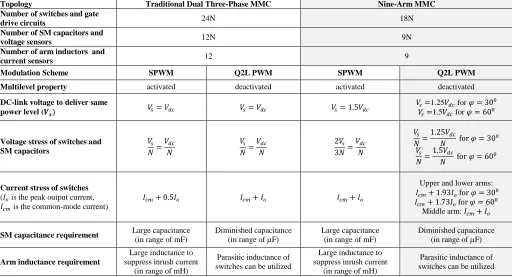
[image:6.612.55.282.353.638.2]dozens of milli farads to only few micro farads, while the arm inductance can be realized through parasitic circuit inductance. Adversely, the merit of employing a reduced component-count means limited voltage magnitude, which necessitates increasing the dc-link voltage to deliver the same power level as traditional MMC configurations. This increases both voltage and current stresses of the MMC cells, where each MMC arm in the proposed approach blocks the full dc-link voltage. Whereas, switching devices in both the upper and lower arms are designed to withstand the sum of the output currents delivered by each leg, while the middle arm’s are rated at the full output current. A detailed assessment of the proposed approach to quantify its features in comparison to other MMC approaches that can deliver six-phase voltages, is summarized in Table III.
VI. CONCLUSION
This paper has presented a nine-arm MMC topology applicable for MV motor drives incorporating six-phase machines. The nine-arm MMC is operated in a Q2L PWM fashion which mimics the PWM VSI two-level operation using an MMC structure with the advantages of indirect series connection such as proper voltage sharing and small voltage steps. Although the multilevel property is lost, the proposed converter retains some key features of the MMC since it has a modular structure which can be readily scaled to higher voltage ratings, in addition to the controllable slopes of output voltage waveform. Compared to a standard six-phase MMC, the nine-arm MMC employs a reduced number of switching devices, capacitors, and inductors. Further, the Q2L PWM of the nine-arm MMC significantly reduces the requirement of both SM capacitance and arm inductance, which reduces drive footprint and its stored energy. The proposed approach was assessed in comparison to traditional MMC topology to highlight its pros and cons. Further, the performance of the proposed approach has been verified through both simulation and experimental results.
TABLEII
PARAMETERS FOR EXPERIMENTATION
Nine-Arm MMC parameters
Number of SMs per arm (N) 3
Rated active power 3 kW
Input dc voltage (𝑉𝑑𝑐) 300 V
Rated current magnitude (𝐼𝑜) 10 A
Nominal SM capacitor voltage (𝑉𝑐) 100 V
Fundamental output frequency (𝑓𝑜) 50 Hz
Dwell time (𝑇𝑑) 50 µs
PWM Carrier frequency (𝑓𝑐) 1 kHz
Arm inductance (𝐿𝑎𝑟𝑚) 20 µH
SM capacitance (C) 50 µF
RL load parameters
Load resistance 8 Ω
[image:7.612.318.564.48.422.2]Load inductance 30 mH
Fig. 11 Experimental results of nine-arm MMC with Q2L PWM at 50 Hz.
REFERENCES
[1] R. D. Klug, N. Klaassen, “High Power Medium Voltage Drives– Innovations, Portfolio, Trends,” 2005 European Conference on Power Electronics and Applications, 11-14 September 2005.
[2] E. Levi, "Multiphase Electric Machines for Variable-Speed Applications," IEEE Trans. Ind. Electron, vol.55, no.5, pp.1893-1909, May 2008.
[3] E. Levi, R. Bojoi, F. Profumo, H. A. Toliyat and S. Williamson, "Multiphase induction motor drives—A technology status", IET Elect. Power Appl., vol. 1, no. 4, pp.489 -516 2007.
[4] C. Lin and C. Hwang, “Multi objective optimization design for a six-phase copper rotor induction motor mounted with a scroll compressor,”
IEEE Trans. Magnetics, vol. 52, no. 7, Article # 9401604, Jul. 2016. [5] M. Duran and F. Barrero, “Recent advances in the design, modeling and
control of multiphase machines—Part II,” IEEE Trans. Ind. Electron.,
vol. 63, no. 1, pp. 459–468, Jan. 2016
[6] D. Glose and R. Kennel, “Continuous space vector modulation for symmetrical six-phase drives,” IEEE Trans. Power. Electron., vol. 31, no. 5, pp. 3837-3848, May. 2016.
[7] M. S. Diab, A. A. Elserougi, A. S. Abdel-Khalik, A. M. Massoud and S. Ahmed, "A Nine-Switch-Converter-Based Integrated Motor Drive and Battery Charger System for EVs Using Symmetrical Six-Phase Machines," IEEE Trans. Ind. Electron., vol. 63, no. 9, pp. 5326-5335, Sept. 2016.
[200.0 V/div] [300.0 µs/div]
v
M1v
U1v
L1[10.0 ms/div] [5.0 A/div]
ia
i
x[500.0 µs/div]
v
cL [20.0 V/div]vcU
v
cM [image:7.612.70.275.507.692.2]TABLEIII
COMPARISON BETWEEN TRADITIONAL DUAL THREE-PHASE MMC AND NINE-ARM MMC
Topology Traditional Dual Three-Phase MMC Nine-Arm MMC
Number of switches and gate
drive circuits 24N 18N
Number of SM capacitors and
voltage sensors 12N 9N
Number of arm inductors and
current sensors 12 9
Modulation Scheme SPWM Q2L PWM SPWM Q2L PWM
Multilevel property activated deactivated activated deactivated
DC-link voltage to deliver same power level (𝑽𝒔)
𝑉𝑠= 𝑉𝑑𝑐 𝑉𝑠= 𝑉𝑑𝑐 𝑉𝑠= 1.5𝑉𝑑𝑐
𝑉𝑠=1.25𝑉𝑑𝑐 for 𝜑 = 30⁰ 𝑉𝑠=1.5𝑉𝑑𝑐 for 𝜑 = 60⁰
Voltage stress of switches and SM capacitors
𝑉𝑠 𝑁=
𝑉𝑑𝑐 𝑁
𝑉𝑠 𝑁=
𝑉𝑑𝑐 𝑁
2𝑉𝑠 3𝑁=
𝑉𝑑𝑐 𝑁
𝑉𝑠 𝑁=
1.25𝑉𝑑𝑐
𝑁 for 𝜑 = 30 0
𝑉𝑠 𝑁=
1.5𝑉𝑑𝑐
𝑁 for 𝜑 = 60 0
Current stress of switches
(𝐼𝑜 is the peak output current, 𝐼𝑐𝑚 is the common-mode current)
𝐼𝑐𝑚+ 0.5𝐼𝑜 𝐼𝑐𝑚+ 𝐼𝑜 𝐼𝑐𝑚+ 𝐼𝑜
Upper and lower arms:
𝐼𝑐𝑚+ 1.93𝐼𝑜 for 𝜑 = 300 𝐼𝑐𝑚+ 1.73𝐼𝑜 for 𝜑 = 600
Middle arm: 𝐼𝑐𝑚+ 𝐼𝑜
SM capacitance requirement Large capacitance
(in range of mF)
Diminished capacitance (in range of µF)
Large capacitance (in range of mF)
Diminished capacitance (in range of µF)
Arm inductance requirement
Large inductance to suppress inrush current
(in range of mH)
Parasitic inductance of switches can be utilized
Large inductance to suppress inrush current
(in range of mH)
Parasitic inductance of switches can be utilized
[8] E. Levi, “Advances in converter control and innovative exploitation of additional degrees of freedom for multiphase machines,” IEEE Trans. Ind. Electron., vol. 63, no. 1, pp. 433-448, Jan. 2016.
[9] A. Bendre, G. Venkataramanan, D. Rosene, and V. Srinivasan, “Modeling and design of a neutral-point voltage regulator for a three-level diode clamped inverter using multiple-carrier modulation,” IEEE Trans. Ind. Electron., vol. 53, no. 3, pp. 718–726, Jun. 2006.
[10] I.-D. Kim, E.-C. Nho, H.-G. Kim, and J. S. Ko, “A generalized undeland snubber for flying capacitor multilevel inverter and converter,” IEEE Trans. Ind. Electron., vol. 51, no. 6, pp. 1290–1296, Dec. 2004. [11] S. Sirisukprasert, J. S. Lai, and T. H. Liu, “Novel cascaded multilevel
converter drive system with minimum number of separated DC sources,” in Proc. IEEE PESC, Vancouver, BC, Canada, Jun. 17–22, 2001, pp. 1346–1350.
[12] M. Saeedifard and R. Iravani, “Dynamic performance of a modular multilevel back-to-back HVDC system,” IEEE Trans. Power Del., vol. 25, no. 4, pp. 2903-2912, Oct. 2010.
[13] M. S. Diab, A. M. Massoud, S. Ahmed, B. W. Williams, "A Dual Modular Multilevel Converter with High-Frequency Magnetic Links Between SubModules for MV Open-End Stator Winding Machine Drives," IEEE Trans. on Power Electron., vol. PP, no.99, pp.1-1.
[14] M. S. Diab, B. W. Williams, D. Holliday, A. M. Massoud and S. Ahmed, "A modular multilevel converter with isolated energy-balancing modules for MV drives incorporating symmetrical six-phase machines," 2017 IEEE Energy Conversion Congress and Exposition (ECCE), Cincinnati, OH, USA, 2017, pp. 2715-2722.
[15] A. A. Elserougi, A. S. Abdel-Khalik, A. M. Massoud and S. Ahmed, “A nine-arm modular multilevel converter (9A-MMC) for six-phase medium voltage motor drives” Industrial Electronics Society, IECON 2015-41st Annual Conference of the IEEE, vol., no., pp.1735-1740, 9-12 Nov. 2015. [16] T. Kominami and Y. Fujimoto, “A novel nine-switch inverter for independent control of two three-phase loads,” in Proc. IEEE Ind. Appl. Conf., New Orleans, LA, USA, 2007, pp. 2346–2350.
[17] T. Kominami and Y. Fujimoto, “Inverter with reduced switching-device count for independent ac motor control,” in Proc. 33rd Annu. Conf. IEEE Ind. Electron. Soc., Taipei, Taiwan, 2007, pp. 1559–1564.
[18] I. Gowaid, G. Adam, A. Massoud, S. Ahmed, D. Holliday, and B. Williams, “Quasi two-level operation of modular multilevel converter for use in a high-power DC transformer with DC fault isolation capability,”
IEEE Trans. on Power Electron, vol. 30, no. 1, pp. 108–123, Jan 2015. [19] A. Mertens and J. Kucka, "Quasi Two-Level PWM Operation of an MMC
Phase Leg with Reduced Module Capacitance," IEEE Trans. on Power. Electron, vol. 31, no. 10, pp. 6765-6769, Oct. 2016.
[20] F. Gao, L. Zhang, D. Li, P. C. Loh, Y. Tang, and H. Gao, “Optimal pulse-width modulation of nine-switch converter,” IEEE Trans. Power Electron., vol. 25, pp. 2331–2343, Sep. 2010.
[image:8.612.52.564.70.347.2]