i
SUPERVISOR ENDORSEMENT
“I hereby declare that I have read through this report entitle “Petri Net Controller Design For Robotic Pick and Place System” and found that it has comply the partial fulfilment for awarding the degree of Bachelor of Electrical Engineering (Control, Instrumentation, and Automation )”.
Signature : ...
Supervisor’s Name : DR. SAIFULZA BIN ALWI
ii
PETRI NET CONTROLLER DESIGN FOR ROBOTIC PICK AND PLACE SYSTEM
MATHIALAGAN A/L VENGADESON
A report submitted in partial fulfilment of the requirements for the degree of
Bachelor in Electrical Engineering (Control, Instrumentation, and Automation)
Faculty of Electrical Engineering
UNIVERSITI TEKNIKAL MALAYSIA MELAKA
iii
DECLARATION
I declare that this report entitle “Petri Net Controller Design for Robotic Pick and Place System” is the result of my own research except as cited in the references. The report has not been accepted for any degree and is not concurrently submitted in candidature of any other degree.
Signature : ...
Name : MATHIALAGAN A/L VENGADESON
iv
DEDICATION
v
ACKNOWLEDGEMENT
First of all, I would like to thank almighty God for the strength and blessings. I would like to express my deepest gratitude to my supervisor, DR. SAIFULZA BIN ALWI for guiding me throughout my final year project development. Knowledge and extra input given by them has highly motivated me to successfully complete this project. The information, suggestions and ideas given by them played huge role in developing a fully functional project.
vi
ABSTRACT
vii
ABSTRAK
viii
TABLE OF CONTENT
CHAPTER TITLE PAGE
ACKNOWLEDGEMENT v
ABSTRACT vi
ABSTRAK vii
TABLE OF CONTENTS viii
LIST OF TABLES xii
LIST OF FIGURES xiv
LIST OF APPENDICES xvi
1 INTRODUCTION
1.1Project Background 1
1.2 Problem Statement 3
1.3Project Overview 4
1.4 Project Objective 4
1.5 Project Scope 4
ix
2.0 Introduction 6
2.1Theory of basic principle of Petri Net 6
2.1.1 Study of Petri Net 7
2.1.2 Concepts and examples of Petri Net 8
2.1.3 Petri Net simulation analysis 10
2.1.4 Important properties of Petri Net 10
2.1.4.1 Liveness 10
2.1.4.2 Safeness 11
2.1.4.3 Reversibility 11
2.1.4.4 Boundedness 11
2.1.4.5 Reachability 12
2.1.5 Application of Petri Net in discrete control system 13
2.1.6 Petri Net working principle 14
2.2Theory of basic principle of KUKA pick and place robot 14
2.2.1 Study of KUKA pick and place robot 14
2.2.2 Robot specification 15
2.2.3 Components of pick and place robot 16
2.2.3.1 Structure 16
2.2.3.2 KUKA robot programming language 17
2.2.3.3 Execution Control 18
2.2.3.4 Actuation 20
2.2.3.5 Vision 20
x
2.2.3.7 Working principle of robot 21
2.3 Programmable Logic Controller (PLC) 22
2.3.1 PLC Programming Language 23
2.3.2 Ladder Diagram (LD) 24
2.4 Summary 25
2.4.1 Comparing Petri Net and Ladder logic 25
2.4.1.1 Design complexity 27
2.4.1.2 Response Time 28
2.5 Conclusion 28
3 METHODOLOGY 3.0 Introduction 29
3.1 Project methodology to achieve first objective. 31
3.1.1 First objective 31
3.2 Project methodology to achieve second methodology 33
3.2.1 Model using Boolean function 33
3.2.2 Block diagram process 42
3.2.3 Hardware used 43
3.2.4 KUKA robot program 44
3.2.5 LD for pick and place operation 49
3.3 Project methodology to achieve third objective 52
3.3.1 Third objective process 53
xi
3.5 Project milestones and Gantt chart 54
3.6 Conclusion 56
4 RESULTS AND DISCUSSION 4.0 Introduction 57
4.1 Simulation Result 57
4.1.1 Model using Petri Net 60
4.1.2 The eight tuple 67
4.1.2 Design of Conversion between LD and PN 68
4.2 Model checking with Petri Net simulator 69
4.2.1 Matrix Place/Transition 70
4.2.2 Reachability 72
4.2.3 P-Invariant 74
4.2.4 T-Invariant 74
4.2.5 Safeness and Boundedness 75
4.2.6 Liveness 75
4.2.7 Reversibility 76
5 CONCLUSION AND RECOMENDATION 78
5.0 Conclusion 78
5.1 Recommendation 79
xii
LIST OF TABLES
TABLE TITLE PAGE
2.1 List of I/O and symbol 7
2.2 Stations in assembly line 16
2.3 Movement of KUKA in three main ways 17
2.4 Inputs and Outputs 18
2.5 Controller logic representation of Petri Nets and Ladder Logic Diagrams 26 2.6 Comparison between LLD and PN 27
3.1 Operation model of axis A1 36
3.2 Operation model of axis A2 37
3.3 Operation model of axis A3 37
3.4 Operation model of axis A4 38
3.5 Operation model of axis A5 38
3.6 Operation model of axis A6 39
3.7 Operation model of gripper 39
3.8 Operation model base loaded position 40
3.9 Operation model pallet area position 40
xiii
3.11 Sensor and control direction 51
3.12 Equipment used in this project 54
3.13 Project Milestones 54
3.14 Gantt Chart 55
xiv
LIST OF FIGURES
FIGURE TITLE PAGE
2.1 A Petri net modelling one operation stage requiring a single resource. 8
2.2 Evolution of markings of PN 9
2.3 PN input and output 10
2.4 Various methods of PN based sequence control 13
2.5 KUKA industrial robot 15
2.6 Servo motor 20
2.7 OMRON SYSMAC CJIM 23
3.1 Flowchart methodology for overall process 30
3.2 The procedure to design a RTPN based discrete event controller 31
3.3 Flow chart for pick and place robot process 34
3.4 Pick and place robot model 35
3.5 Robot axis movement 35
3.6 Initial position of robot arm 36
3.7 The block diagram above shows the working of the system 42
3.8 KR C4 robot controller for pick and place robot 43
xv
3.10 SIM KUKA program (a) 44
3.11 SIM KUKA program (b) 45
3.12 SIM KUKA program (c) 45
3.13 SIM_AUTO KUKA program (a) 46
3.14 SIM_AUTO KUKA program (b) 46
3.15 SIM_AUTO KUKA program (c) 47
3.16 Ladder Diagram to control KUKA robot pick and place operation (a) 49
3.17 Ladder Diagram to control KUKA robot pick and place operation (b) 50
3.18 Ladder Diagram to control KUKA robot pick and place operation (c) 51
4.1 PN controller design for pick and place robotic system 58
4.2 Souvenir clamping process 62
4.3 Souvenir unclamping process 63
4.4 Return to home position 64
4.5 Error recovery process 65
4.6 Mutually exclusive 66
4.7 Simulating process 67
4.8 Properties analysis of pick and place controller design 70
4.9 Place and transition in matrix 71
4.10 Reachability of pick and place controller design 72
4.11 Place invariant 74
4.12 Transition invariant 74
xvi
LIST OF APPENDICES
1
CHAPTER 1
INTRODUCTION
In this chapter, project background, problem statement, project overview, objective and the scope of the project will be presented.
1.1Project background
The logic control system is operate by turning on off motors, switches, valves, and other devices in response to operating conditions and as a function of time. Basically the control problem is to cause/ prevent occurrence of:
i. Particular values of outputs process variables
ii. Particular values of outputs obeying timing restrictions iii. Given sequences of discrete outputs
iv. Given orders between various discrete outputs
2 Robots should be easier to use for more applications, and Southwest Research Institute, SwRI established ROS-Industrial, open source industrial robotic software and working group, to broaden the application of robotics and increase robotic interoperability. ROS stands for robotic operating system. As more manufacturing facilities and distribution centres discover the benefits of robotic material handling solutions, they must decide how best to control the robot. While robot original equipment manufacturers (OEMs) offer their own tightly integrated controller, recent developments have enabled control by a Petri Net. Adding open-control software such as Petri Net to the convergence of well-known controls principles makes it possible to create machine designs that feature seamlessly integrated robots. This results in game-changing advantages for machine builders and manufacturers and the ability to integrate robot technology into more applications, including those that are traditionally among the most cost-sensitive.
The cost-saving benefits that make this possible include: reduced wiring, network and software platforms that are shared with the overall machine automation system, and a significantly reduced machine footprint. This has led to higher performance mechatronic and robotic solutions, including product packaging with variable product flow and complex material handling lines.
Petri Net is one of several mathematical modelling languages for the description of distributed systems Petri Nets and their concepts have been extended and developed, and applied in a variety of areas. A Petri Net is a collection of directed arcs connecting places and transitions. Places may hold tokens. A design method controller for a manufacturing assembly cell modelled by aPetri net will be presented. The control goal is to enforce a set of linear constraints on the marking behaviour or state of the Petri net. The method discussed here is a powerful means of realizing these constraints because it is simple to calculate, and the Petri net structure of the solution makes the controller easy to implement. The controller computation is derived using the concept of Petri net place invariants. [10]
Last but not least, to be precisely this project is about the KUKA robot pick and place system controlled using PN simulation. This robot is a part from eight stations which available to complete a disc casing loading and unloading assembly line. It is the 7th station
3 boundedness, reachability, liveness and reversibility. The model of pick and place operation in Boolean function occupies design of robotic arm and position of sensors and axis.
1.2 Problem Statement
Initially, many industries use Programmable Logic Controller (PLC) as controller for their machines. This is because PLC is a microcontroller that can act as a central processor unit to control the sensor and other devices using the program which being design by the user itself. PLC system very precise to be used in the packaging workstation because it can be programmed by the operation of sequence instruction. At the same time, the design of PLC requires to maintain the quality of product and reduce the time to operate. As the complexity of the application increases, it is very crucial to ensure the safeness, liveness and reversibility properties of the system, while to maintain the performance of the system.
4
1.3 Overview of the project
The project is about designing a controller for the pick and place robotic system using PN. Petri Net still a new software which also able to function as logic controller for the robots. It is more convenient and easy to handle compare to other types of controller which are already in use. In this project, the pick and place operation also modelled in Boolean function. Thus it gives a better view of the process, inputs and outputs of the KUKA robotic arm. In the next chapter, the use advantages and techniques used in Petri Net will be discussed in further.
1.4 Objectives
Objectives of this project are:
1. To analyse the Petri Net simulation for logic control system. 2. To model pick and place robotic system using Boolean function
3. To design a controller for pick and place robotic system by using Petri Net
1.5 Scope
6
CHAPTER 2
LITERATURE REVIEW
2.0 Introduction
This chapter present about some basic principle and theories in the project and review of previous journals about the Petri Net (PN), Boolean function for pick and place robot system, KUKA pick and place robot, KUKA programming language and the PN controller design for KUKA pick and place robot system. In addition, the history of PN and KUKA pick and place robot also provided in this chapter. Besides that, this chapter also explained the implementation of PN in discrete control system. Last but not least, the comparison between PN and other types of controller are also included in this chapter.
2.1Theory of basic principle of Petri Net
7
2.1.1 Study of PN
There are many techniques used for mathematical modelling of system. Which are namely basic queuing networks, queuing system with MM1 queuing, Fuzzy Net and close doing networks. Petri Net is another form of mathematical modelling to formally specify a particular system. Petri Net (PN) was invented by Carl Adam Petri in his PhD thesis in 1962 and initially had the form of Condition/Event Systems with simple arcs and binary marking. After that, there are a few modification of the basic system model done, which includes the integer markings and weighted arcs. [10]
PN used to model the functionality and behaviour of a system. It also can derive some performance result. In term of application, it can use in computer systems, computer networks and protocols, manufacturing system, production system, scheduling systems and controllers. PN also used to combine the computer system and manufacturing system by testing or checking the behaviour of certain components and parts. [1]
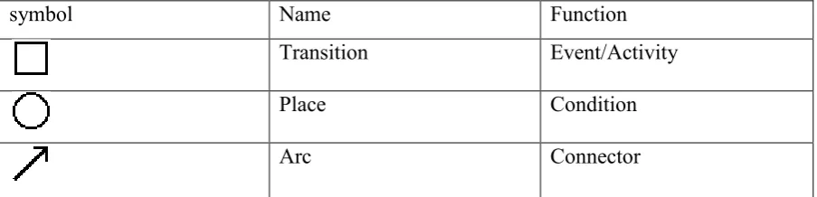
[image:23.595.80.532.661.770.2]PN is a formal language to represent system and also a graphical language for modelling systems with concurrency. PN have an exact mathematical definition of their execution semantics, with proper mathematical theory for process analysis. Indirectly, a Place/Transition (P/T) Petri net is known as a bipartite graph. It consists of two types of nodes places and transition. Places typically drawn as circles and transition represented by bars or rectangles. Place represent condition where the condition needs to be full filled and the transition is described as an event that occur or processing activity. When condition is satisfied transition will trigger. Then, there is a changing in system from one state to another by transition. Symbols used in PN are given in Table 2.1.
Table 2.1: List of Input/output and symbol
symbol Name Function
Transition Event/Activity
Place Condition
8
Token Number of resourses
Places and transitions are interconnected by directed arcs. Arcs only exist in between places and transition or vice versa. Arc always connects two nodes of different types. Arc can be weighted, which is representation of set of parallel arcs. There are tokens exist between the places and transitions. It circulates in this system via the transitions.
2.1.2 Concepts and examples of Petri Net
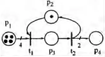
A marked Petri net (PN) Z = (P, T, I, O, m) is a five tuple where 1. P is a finite set of places
2. T is a finite set of transitions with P U T≠ 0 and P ∩ T=0
3. I: P x T →N, is an input function that defines the set of directed arcs from P to T where N= (0, l, 2,. . .}
4. O: P x T→ N,is an output function that defines the set of directed arcs from T to P 5. m: P→ N, is a marking whose ith component represents the number of tokens in the
i th place. An initial marking is denoted by mo.
[image:24.595.219.389.607.699.2]Example 1: A marked PN is shown in figure 2.1 and its formal description is given as follows: