ISSN (Print) : 2320 – 3765 ISSN (Online) : 2278 – 8875
I
nternational
J
ournal of
A
dvanced
R
esearch in
E
lectrical,
E
lectronics and
I
nstrumentation
E
ngineering
(An ISO 3297: 2007 Certified Organization)
Vol. 4, Issue 9, September 2015
Design, Implementation & Performance
Evaluation of High Speed ARM Processor
Based Under & Over Voltage Protective Relay
Venkateshmurthy.B.S1, Dr.K.R.Nataraj2
Research Scholar, Dept. of Electrical Engineering, Jain University, Bangalore, India1 Professor & HOD, Dept of ECE, SJBIT. Bangalore, India2
ABSTRACT: In this paper the protection of power system based on ARM technology, the design and construction of
low cost under and over voltage protective device which was fabricated using ARM controller. The ARM processor is at the heart of the device which performs the major control of the device. The device is simple and of low cost. This device can be employed as standalone equipment between main supply and the load. This ARM processor based under & over voltage relay provides over/under voltage protection and also protection against transients. And also this paper includes the watch dog timer concept included in processor.
KEY WORDS: ARM Processor, Watch Dog Timer, over voltage, under voltage, protection.
I.INTRODUCTION
Voltage irregularities are one of the greatest power quality issues facing industry and home today and often times, is responsible for damaging valuable electrical equipment. Electrical Power System protection is required for protection of both user and the system equipment from fault; hence electrical appliances are not allowed to operate without any protective device installed. Power System fault is defined as undesirable condition that occurs in the power system, and the undesirable conditions are short circuit, current leakage, ground short, over current, under and over voltage.
Technically speaking, an over/under voltage condition is reached when the voltage exceeds/lags the nominal voltage by 10% for more than 1 minute. Short duration voltage events can also occur such as transients (both impulsive and oscillatory), sags/dips and swells. Short duration intermittent supply failures can last anywhere from 0.5 cycles up to 1 minute and can caused by a number of occurrences such as supply system faults, equipment failures, or malfunctions in control equipment. Under-voltage might result into brownout, distortion or permanent damage while overvoltage in the form of spikes and surges could cause distortion, burn-out, melt- down, fire, electro-pulsing and permanent damage.
Owing to the continual damages done by fluctuations in the power supply, there is n e e d to address the problem through other alternatives, which give birth to design and construction of an equipment to protect the connected loads against under and over voltage supply. Under and over voltage protection is needed between supply terminal and the appliances (connected loads).
II. MATERIALS AND METHODS
ISSN (Print) : 2320 – 3765 ISSN (Online) : 2278 – 8875
I
nternational
J
ournal of
A
dvanced
R
esearch in
E
lectrical,
E
lectronics and
I
nstrumentation
E
ngineering
(An ISO 3297: 2007 Certified Organization)
Vol. 4, Issue 9, September 2015
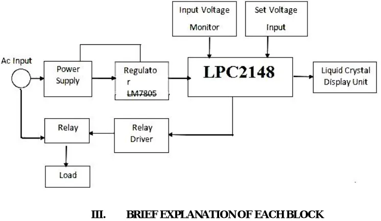
above the pre-set range of values. The under voltage and the over voltage protective device is shown in Block diagram in Figure 1.
.
Figure 1. ARM processor Based under voltage and the over voltage
III. BRIEF EXPLANATION OF EACH BLOCK
AC Input: This is the input supply from the public utility where the device will be energized. It is also supplied directly to the relay contacts in the device which connects the load to the supply when the supply is within 200V – 240V range.
(1) Power Supply: The power supply uses a step down transformer to step down the input mains voltage to a voltage level suitable for the electronics within the device. A centre tapped transformer, with two diodes for full wave rectification is used to convert the ac voltage to a pulsating dc voltage followed by a filter, After the rectification and smoothening, a sample of the output voltage is fed to the microcontroller through a potentiometer. This voltage is unregulated and therefore varies as the input mains voltage varies. The output voltage is also passed to an LM7805 positive voltage regulator to provide a regulated +5V supply for the micro-controller. The regulator served to reduce further the ripple and noise in the regulated supply to the LPC2148 microcontroller. The regulator also provides current limiting and protects the power supply and attached circuit from over current Since the system is to prevent against over and under voltage, the transformer was designed and the windings were so selected for the device to be able to sense and withstand input mains voltage up to 600Vac. (2)The LPC2148 microcontrollers are based on a 16-bit/32-bit ARM7TDMI-SCPU with real-time emulation and embedded trace support, that combine microcontroller with embedded high-speed flash memory ranging from 32 kB to 512 kB. A 128-bit wide memory interface and a unique accelerator architecture enable 32-bit code execution atthe maximum clock rate. For critical code size applications, the alternative 16-bit Thumb mode reduces code by more than 30 % with minimal performance penalty.
Due to their tiny size and low power consumption, LPC2148 are ideal for applications where miniaturization is a key requirement, such as access control and point-of-sale. Serial communications interfaces ranging from a USB 2.0 Full-speed device, multiple UARTs, SPI, SSP to I2C-bus and on-chip SRAM of 8 kB up to 40 kB, make these devices very well suited for communication gateways and protocol converters, soft modems, voice recognition and low end imaging, providing both large buffer size and high processing power. Various 32-bit timers, single or dual 10-bit ADC(s), 10-bit DAC, PWM channels and 45 fast GPIO lines with up to nine edge or level sensitive external interrupt pins make these microcontrollers suitable for industrial control and medical systems.
ISSN (Print) : 2320 – 3765 ISSN (Online) : 2278 – 8875
I
nternational
J
ournal of
A
dvanced
R
esearch in
E
lectrical,
E
lectronics and
I
nstrumentation
E
ngineering
(An ISO 3297: 2007 Certified Organization)
Vol. 4, Issue 9, September 2015
feed the microcontroller. It helps the microcontroller to monitor the supply voltage, as the value of this voltage varies as the input mains voltage varies. The unregulated dc supply voltage is scaled down by the potentiometer to values suitable for the micro-controller. Input mains voltage up to 600Vac can be monitored.
(4)Liquid Crystal Display (LCD): This displays the supply voltage as well as some information at “switch on‟ or when the supply voltage is out of range of the desired pre-set range of values. The LCD used is LM016L having a 2 x 16 display. The picture of the LCD is shown in Figure 2.
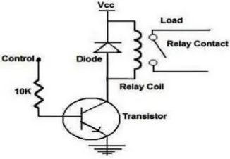
(5) Relay Driver: This is an NPN transistor that controls and supplies current through the coil of the relay that connects the mains supply to the load. The relay is a single pole relay which, upon being activated by the PIC via the transistor, makes under normal mains supply voltage and brakes under abnormal mains supply voltage
Figure(ii). Relay Driver circuit
IV.INTERFACING –A RELAY TO ARM 7 CONTROLLERS
Relays are devices which allow low power circuits to switch a relatively high current/voltage on /off. A relay circuit is typically a smaller switch or device which drives (open /closes) an electric switch that is capable of carrying much larger current amounts.
Figure below shows the interfacing of the Relay to ARM controller. When the input is energized the relay turns on and the + output connected to +12v, when the relay is off the + output is connected to ground. The – output is permanently wired to ground. the relay is interfaced to p0.30 pin through an opto isolator. This opto isolator protects the port pin from damage to any high currents. the opto isolator consists of a pair of an LED and a photo transistor as shown in diagram.
Fig(iii) Interfacing circuit
ISSN (Print) : 2320 – 3765 ISSN (Online) : 2278 – 8875
I
nternational
J
ournal of
A
dvanced
R
esearch in
E
lectrical,
E
lectronics and
I
nstrumentation
E
ngineering
(An ISO 3297: 2007 Certified Organization)
Vol. 4, Issue 9, September 2015
relay is in off state. Similarly when we apply a low to the transistor the output is high and the relay is on
IV. WATCHDOG TIMER
Most embedded systems need to be self-reliant. It's not usually possible to wait for someone to reboot them if the software hangs. Some embedded designs, such as space probes, are simply not accessible to human operators. If their software ever hangs, such systems are permanently disabled. In other cases, the speed with which a human operator might reset the system would be too slow to meet the uptime requirements of the product.
A watchdog timer is a piece of hardware that can be used to automatically detect software anomalies and reset the processor if any occur. Generally speaking, a watchdog timer is based on a counter that counts down from some initial value to zero. The embedded software selects the counter's initial value and periodically restarts it. If the counter ever reaches zero before the software restarts it, the software is presumed to be malfunctioning and the processor's reset signal is asserted. The processor (and the embedded software it's running) will be restarted as if a human operator had cycled the power.
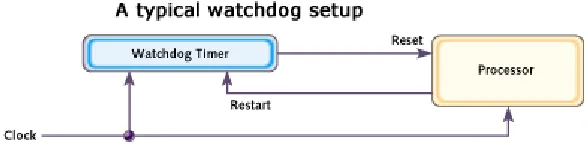
Figure (iv) shows a typical arrangement. As shown, the watchdog timer is a chip external to the processor. However, it could also be included within the same chip as the CPU. This is done in many microcontrollers. In either case, the output from the watchdog timer is tied directly to the processor's reset signa
Fig(iv) watch dog setup
The process of restarting the watchdog timer's counter is sometimes called "kicking the dog." The appropriate visual metaphor is that of a man being attacked by a vicious dog. If he keeps kicking the dog, it can't ever bite him. But he must keep kicking the dog at regular intervals to avoid a bite. Similarly, the software must restart the watchdog timer at a regular rate, or risk being restarted. Watch dog Timer is an additional timer that does a monitoring job and resets the system if necessary. The scenario is this Most embedded systems are excepted tobe self reliant there is very little possibility of intervention by a human operator in case the associated software goes away by getting stuck in an infinite loop. Some embedded systems are placed in inaccessible sites like factory environments, space probes etc when the software is detected to be malfunctioning, the best way is to reset and start again, such anomalies can occur due to various reasons like dead locks (in a multi tasking environment) a noise voltage on some pin which may cause wrong triggering and so on.the point is that if such a situation arises, there should be a mechanism by which this is automatically detected and gets the system to reset. The watch dog timer is like any other timer. It can be loaded with a count which decrements down to zero when it reaches zero, it resets the processor. For a system which is doing its job correctly, the watch dog timer will never count down to zero, before that the ‘correctly operating’ software will restart it periodically and reload its original count, so as to prevent it from counting down to zero. What is the number loaded as the ‘count’ in a WDT. This is decided by considering how much time is to be allowed for the system to recover(on its own)before it is to be forcibly reset. Figure shows the way a watch dog timer operates. This is the case when the WDT is external to the processor, the 8051 family of MCU’s don’t have an internal WDT but most other MCU families like PIC, AVC, ARM etc have it as an internal timer. When the processor gets by the WDT, it is called a soft reset or a warm boot.
ISSN (Print) : 2320 – 3765 ISSN (Online) : 2278 – 8875
I
nternational
J
ournal of
A
dvanced
R
esearch in
E
lectrical,
E
lectronics and
I
nstrumentation
E
ngineering
(An ISO 3297: 2007 Certified Organization)
Vol. 4, Issue 9, September 2015
This below table explains the difference between ARM & different microcontrollers available today and used nowadays most, here we classify different microcontroller according to their feature and it show that how they are different from each other.
Table(i) comparison between ARM & other microcontrollers
]
CONCLUSION
The aim of designing and constructing a low cost ARM Processor based under and over voltage protective device was achieved in this work. The device supplies power to the connected load whenever the input supply is within the required pre set voltage. Thereby protecting the output connected loads from unnecessary damages. The Protective Relay is found to be more economical.
REFERENCES
[1] Wang Jing, He H Uiming , ARM Based Embedded Video Monitoring System Research,”2010 IEEE978-1-4244-5540.
[2] ARM Cortex-M3 Processorreferencemanual:
Http//Infocenter.Arm.Com/Help/Topic/Com.Arm.Doc.Ddi0337e/DDI0337E_Cortex_M3_Rlpl_Trm.Pdf Peterson,L.L. 1993. [3] Gurevich H., And Vladimir S. (2005) “Electrical Relays: Principles And Applications” CRC Press, London- New York. [4] Ian S. L. (2000) “Passive Components For Circuit Design”, Texas, USA, P. 170. ISBN 008051359X.
[5] Maddock R. J. And Calcute P. (1994) “Electronics: A Course For Engineers” 2nd Edition; Longman Essek, London.
[6] Close K. J., And Yarwood J. (1979) “Experimental Electronics For Students” 1st Edition, Chapman And Hall Ltd, Britain.
[7] Martin P. B. (2008) “Programming 8-Bit PIC Microcontrollers In C With Interactive Hardware Simulation” ISBN: 978-0-7506-8960- [8] Keil-4ideuser Manual: Http://Www.Keil.Com/Support/Man/Docs/Uv4/.