International Journal of Research (IJR)
e-ISSN: 2348-6848, p- ISSN: 2348-795X Volume 2, Issue 09, September 2015Available at http://internationaljournalofresearch.org
The Design of Advanced Industrial or Building Area
Network Control Using Zigbee
M.Vishwanath
1& M.LokeshCharan
2M. Vishwanath1*, [email protected]
M.LokeshCharan2*, [email protected]
Assistant Professor, Electronics & Communication Engineering, MLRITM, Hyderabad, Telangana, India
Abstract—
The paper describes the zigbee building Area Network to cater for high traffic communication in Building Area Network(BAN), The Existing Method of reference paper has the framework designed to co-ordinate the operation between multiple interfaces based on newly define tree based mesh which is a following zigbee topology and it is named as MIZBAN with experiment carried in Five Floor Building but we are
implementing the similar process and
demonstrating with a prototype having two zigbee nodes communicating on point to point basis the ZigBee BAN is recommended because they are low power consuming devices and the supports the communication up to One Kilo meter Range. In light of the development of BAN, a generic architecture of ZigBee BAN (ZBAN) is proposed in this paper. The proposed ZBAN may be easily,
accurately, and efficiently deployed in
high-density-traffic BANs, such as in high rises..
Keywords— ARM7; temperature; LDR ;XBEE
I. INTRODUCTION
ZigBee belongs to the class of wireless sensor networks whose adoption bears a crucial meaning. It was discussed that, because of the inherent nature of scalability and mesh capability of ZigBee, ZBAN for AMI can be established and set up quickly in most existing buildings at a lower cost. Such an adaptive and scalable wireless structure will certainly help to build up an efficient demand response smart metering infrastructure for various smart grid applications.
A good demand and response smart metering system will help the gross domestic product (GDP) grow healthily (less carbon emission) to a great extent. Attention should be drawn to the fact that traffics in a BN in a high-rise BAN is a few hundred times more than in a traditional
II. SYSTEMARCHITECTURE
The system architecture of this proposed system is divided into two different and independent blocks.
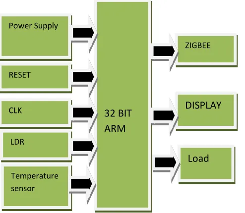
ARM7 END: Hardware implementation for this
International Journal of Research (IJR)
e-ISSN: 2348-6848, p- ISSN: 2348-795X Volume 2, Issue 09, September 2015Available at http://internationaljournalofresearch.org
Figure – 1: Block Diagram of ARM7 END
8051 END (ROUTER END): This is fixed in
between ARM End other 8051 END , simply it will works as a router between two nodes.
Figure – 2: Block Diagram of 8051 END
8051 END: At this end the load switches are
interfaced to this end, based on the LDR, Temperature we can control the loads at ARM end.
Figure – 3: Block Diagram of 8051 END
III. IMPLEMENTATION
HARDWARE:
In this project Hardware implementation has divided into two different parts, one was at ARM7
end and other was 8051. Let’s see individual
hardware implementation.
At ARM7 End hardware implementation, ARM processor plays a key role in monitoring and controlling the security system. Low-power consumption ARM processor (LPC2148) operating at 3.3V, 50uA is designed and mounted on a PCB along with Reset Circuit and a Clock Circuit. LPC2148, a 32-bit microcontroller with advanced RISC architecture and having 48 GPIO lines with a program memory of 32KB and a data memory of 512Bytes.
For critical code size applications, the alternative 16-bit Thumb mode reduces code by more than 30 % with minimal performance penalty. Due to their tiny size and low power consumption, LPC2141/42/44/46/48 are ideal for applications where miniaturization is a key requirement, such as access control and point-of-sale. Serial communications interfaces ranging from a USB 2.0 Full-speed device, multiple UARTs, SPI, SSP to I2C-bus and on-chip SRAM of 8kB up to 40kB, make these devices very well suited for communication gateways and protocol converters, soft modems, voice recognition and
32 BIT ARM
ZIGBEE
DISPLAY Power Supply
RESET
CLK
Load
8 BIT 8051 Power
Supply
ZIGBEE
DISPLAY CLK
8 BIT 8051 Power
Supply
GPIO SWITCHES
(Sw1, Sw2)
ZIGBEE
DISPLAY
CLK LDR
International Journal of Research (IJR)
e-ISSN: 2348-6848, p- ISSN: 2348-795X Volume 2, Issue 09, September 2015Available at http://internationaljournalofresearch.org
low end imaging, providing both large buffer size and high processing power. Various 32-bit timers, single or dual 10-bit ADC(s), 10-bit DAC, PWM channels and 45 fast GPIO lines with up to nine edge or level sensitive external interrupt pins make these microcontrollers suitable for industrial control and medical systems.
Figure – 4: ARM Overview [LPC2148]
Figure – 5: LPC2148 Development Board
Here, in the above figure the clock circuit and reset circuits were assembled along with the LCD display circuit. A 16 X 2 LCD display is used for displaying the status of the system.
Temperature Sensor: The Temperature sensor
(LM 35) is interfaced at ARM7. LM35 series are precision integrated-circuit temperature. The LM35 requires no external calibration since it is internally calibrated. The LM35 does not require any external calibration or trimming to provide typical accuracies of ±1⁄4°C at room temperature
and ±3⁄4°C Over a full -55 to +150°C temperature
range.
The LM35’s low output impedance, linear
output, and precise inherent calibration make interfacing to readout or control circuitry especially easy. It can be used with single power supplies, or with plus and minus supplies. As it draws only 60 μA from its supply, it has very low self-heating, less than 0.1°C in still air. The characteristics of LM35 sensor shown below:
Figure – 4: LM35 characteristics
For each degree of centigrade temperature it outputs 10 milli volts.
In this project I’ve connected LM35 TO ARM7
(LPC 2148). The output of LM35 would be in the form of Analog, to convert analog to digital I’ve
used ADC. The output of LM35 given to the ADC and the output of ADC is in the form of digital..
LDR (Light Dependent Resistor): The LDR sensor
is very useful especially in light/dark sensor circuits. Normally the resistance of an LDR is very high, sometimes as high as 1,000,000 ohms, but when they are illuminated with light, the resistance drops dramatically. The LDR sensor is shown below:
International Journal of Research (IJR)
e-ISSN: 2348-6848, p- ISSN: 2348-795X Volume 2, Issue 09, September 2015Available at http://internationaljournalofresearch.org
transistor and then the second transistor. The circuit connection of LDR is shown below:
Figure –7: LDR Sensor Circuitry
LCD: LCD has used in this project for display
status of the system. Interfacing LCD to LPC 2148 has shown below:
Figure – 6: LCD Display Interfacing
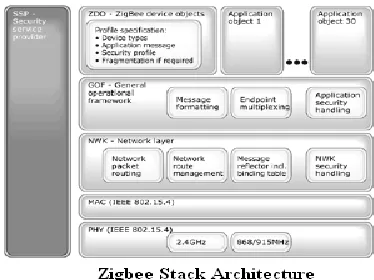
XBEE: ZigBee is an IEEE 802.15.4 standard for
data communications with business and consumer devices. It is designed around low-power consumption allowing batteries to essentially last forever. The ZigBee standard provides network, security and application support services operating on top of the IEEE 802.15.4 Medium Access Control (MAC) and Physical Layer (PHY) wireless standard. It employs a suite of technologies to enable scalable, self-organizing, self-healing networks that can manage various data traffic patterns. Architecture of XBEE module has shown below:
Figure – 7: ZigBee Architecture
8051 End: 8051 is an 8-bit processor, meaning
that the CPU can work on only 8 bits of data at a time. Data larger than 8 bits has to be broken into 8-bit pieces to be processed by the CPU. 8051 is available in different memory types such as UV-EPROM, Flash and NV-RAM.8K Bytes of Re-programmable Flash Memory. RAM is 256 bytes.4.0V to 5.5V Operating Range. Fully Static
Operation: 0 Hz to 33 MHz’s Three-level
Program Memory Lock.256 x 8-bit Internal RAM.32 Programmable I/O Lines. Three 16-bit Timer/Counters. Eight Interrupt Sources. Full Duplex UART Serial Channel.Low-power Idle and Power-down Modes. Interrupt recovery from power down mode. Watchdog timer.Dual data pointer. Power-off flag. Fast programming time.Flexible ISP programming (byte and page mode). Pin diagram of 8051 has given below:
International Journal of Research (IJR)
e-ISSN: 2348-6848, p- ISSN: 2348-795X Volume 2, Issue 09, September 2015Available at http://internationaljournalofresearch.org
The architecture of 8051 has shown below:
Figure – 9: 8051 Architecture
The remaining modules like Switches, Temperature sensors, LDR Sensor were assembled.
SOFTWARE:
Here, to program ARM processor KeiluVision 4 was used as a cross-compiler and Flash Magic was used as a programmer.
ALGORITHM & FLOWCHART ALGORITHM:
Step – 1: Initialize ARM, LCD, XBEE Step – 2: Press Button in 8051 End
Step – 3: Transmit message data from 8051 End to router End (8051 END) using XBEE Communication.
Step – 4: Router end transmits data to the ARM End using XBEE communication.
Step – 5: XBEE Transceiver in ARM End will receive information, and loads will be on or off.
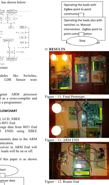
FLOWCHART:
The flowchart of this paper is as shown below:
Figure – 10: Flow Chart
IV. RESULTS
Figure – 11: Final Prototype
Figure – 11: ARM END
Figure – 12: Router End
Start
Acquiring sensor data
Operating the loads with ZigBee point to point communication
Operating the loads also with switches i.e. Manual
intervention ZigBee point to point communication
International Journal of Research (IJR)
e-ISSN: 2348-6848, p- ISSN: 2348-795X Volume 2, Issue 09, September 2015Available at http://internationaljournalofresearch.org
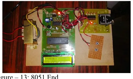
Figure – 13: 8051 End
V. CONCLUSION
Here,The Industrial/building area network control
using Zigbee communication is designed and
proposed and it is widely used in security and safety applications
ACKNOWLEDGEMENT
I would like to express my special thanks and
gratitude to AsstProf M vishwanath,K. N.
BHUSHAN, Assoc. Prof & HOD ECE, Marri Laxman Reddy Institute of Technology& Management as well as our Principal Dr. K Venkateswara Reddy, M. Tech., Ph.D., MISTE, who gave me the golden opportunity to do this wonderful project on the topic (The design of advanced Industrial/building area network control using Zigbee), which also helped me in doing a lot of Research and I came to know about so many new things. Secondly I would like to thank my parents and friends who helped me a lot in finalizing this project within the limited time frame
REFERENCES
[1]http://www.engineersgarage.com/armprojects/i ntroduction-to-arm-microcontroller-lpc2148
[2]https://www.pantechsolutions.net/microcontrol ler-boards/user-manual-arm7-lpc2148
development-kit
[3] http://www.nex-robotics.com/lpc2148- development-board/arm7-lpc2148-development-board.html
[4]http://www.futurlec.com/Philips/LPC2148FBD 64pr.shtml
[5] http://www.ti.com/product/lm35
[6]http://www.digikey.com/catalog/en/partgroup/l m35/11023?WT.srch=1&mkwid=sUTk75Oa8&p crid=73168693384&pkw=_cat%3Adigikey.com& pmt=b&pdv=c
[7]http://www.facstaff.bucknell.edu/mastascu/eles sonsHTML/Sensors/TempLM35.html
[8] https://en.wikipedia.org/wiki/Photoresistor
[9]https://en.wikipedia.org/wiki/Zigbee
BIOGRAPHY:
Asst.Prof. M.vishwanath has completed B.Tech&M.Tech from JNTU HYDERABAD. He is pursuing Ph.D in the area of Wireless Communication from KLU UNIVERSITY.
![Figure – 4: ARM Overview [LPC2148]](https://thumb-us.123doks.com/thumbv2/123dok_us/7795533.1293229/3.612.51.266.194.530/figure-arm-overview-lpc.webp)