Copyright to IJIRSET www.ijirset.com 2043
MATERIAL SELECTION AND TESTING
OF HACKSAW BLADE BASED ON
MECHANICAL PROPERTIES
Prof. Nitinchandra R. Patel
1, Mohammed A. Vasanwala
2, Balkrushna B. Jani
3,Miteshkumar D. Rathwa
4,
Ravi A. Thakkar
5Assistant Professor, Department of Mechanical Engineering, G.H. Patel College of Engineering & Technology , Vallabh vidyanagar, Gujarat, India1
Final Year Student, Department of Mechanical Engineering, G.H.Patel Collegeof Engineering & Technology, Vallabh vidyanagar, Gujarat, India 2, 3, 4, 5
Abstract: Testing of different material blades like High Carbon Steel, Low Alloy Steel, Bi-metallic blade, High speed Steel blades for their hardness, Cutting time performance, Wear Resistance, Tensile Strength and performance under buckling. Experiment of Rockwell Hardness tester for getting Hardness Number on C-Scale for all different types of blades, so their relative hardness of teeth of different blade blades can be compared. For Cutting Performance test, Cutting of same diameter (25mm) job of different materials like Aluminium, Brass, Copper by all blades and their cutting time is noted and compared. For Wear Resistance ability, Profiles of blades-before and after cutting are developed with the help of profile projector and compared. For figuring out Tensile Strength , we carried out Tension test on Universal Testing Machine (UTM), by finding out Modulus of Elasticity (E) value and further analytical calculation can be done for finding Maximum Permissible deflection. Here, we have found out the better blade material for different materials under different mechanical consideration.
Keywords: Hardness, Wear Resistance, Tensile Strength , Permissible Deflection of blade I. INTRODUCTION
A hacksaw is a fine-tooth saw with a blade under tension in a frame, used for cutting materials such as metal. Hand-held hacksaws consist of a metal frame with a handle, and pins for attaching a narrow disposable blade. A screw or other mechanism is used to put the thin blade under tension. Hacksaw blade cutting is conventional machining process which works on the principle of metal cutting. Where harder material which is tooth of the blades cuts the relatively softer material as per need.A power hacksaw (or electric hacksaw) is a type of hacksaw that is powered by electric motor. Most power hacksaws are stationary machines but some portable models do exist. Stationary models usually have a mechanism to lift up the saw blade on the return stroke and some have a coolant pump to prevent the saw blade from overheating. The saw or saw blade is the one of the most important component of a sawing machine. Saws are characterized by their material, tooth form, teeth set, tooth spacing and size. The geometry of the teeth is singular to that of the single point tools. The straight tooth form is suitable for finer pitches whereas the undercut face tooth forms are used for coarser pitches. Undercut tooth form is better from design point of view, because the cutting edges are backed up by more metal. It is very difficult to have this tooth form if teeth are very small in size.For the maximum efficiency for cutting process, hacksaw blade is fixed at 30◦ inclined to the work piece. Here, due to relative motion between work piece and hacksaw blade, heat is generated which is not desirable because it leads to more wear of blade tooth as we as will change the properties of final product. Therefore cutting fluids popularly known as coolants are applier while the cutting process. Different coolants are used as per the material to be cut
FIG. 1 Hacksaw blades
This are the Four Blades which we used for testing all different aspects as stated above: From the top, blades are having materials
Copyright to IJIRSET www.ijirset.com 2044
II. MATERIALTESTING
A. HARDNESS TEST
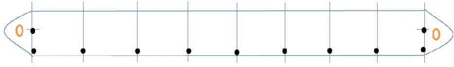
We have carried out Hardness test on Harness Tester Machine on C- Scale with diamond Indenter in HRC Unit. We have done the hardness test on the hacksaw bladesconsidering different points on the blade at equal distance on the edge near tooth at distance of 5 cm. as well as at the middle of blade at both the ends and measuring the hardness on these points as shown in below figure.
FIG. 2 Location of Points at which hardness readings are taken.
Material 1:- High Carbon steel (HCS)
Distance 0 5 10 15 20 25 30 35 40
Hardness 49 51 52 53.5 51 57 55 57.5 46.5
Material 2 :- Low Alloy steel
Distance 0 5 10 15 20 25 30 35 40
Hardness 36.5 65 64.5 65.5 62.5 62 62 64 32.5
0 10 20 30 40 50 60 70
0 5 10 15 20 25 30 35 40
H
A
R
D
N
ES
S
DISTANCE (cm)
Hardness(C Scale) 0
10 20 30 40 50 60 70
0 5 10 15 20 25 30 35 40
H
A
RD
NE
SS
DISTANCE (cm)
Copyright to IJIRSET www.ijirset.com 2045
Material 3:- Bi-Metallic
Material 4:- High Speed Steel (HSS)
Distance 0 5 10 15 20 25 30 35 40
Hardness 45 60.5 60 61.5 64 59.5 64.5 59.5 44
B. CUTTING PERFORMANCE (CUTTING TIME)
We have performed cutting opearation of these four blades on three different materials and the cutting action was followed in sequence which are as follows:
1. Aluminium 2.Brass 3. Mild steel
We have taken cutting time for same diameter jobs of above materials so we can find about the relative cutting performance. Here 25 mm Diameter of work piece is taken for being cut , this 25 mm round cross section is common for all different work pieces to be cut. Also we have taken profiles of blades on Profile Projector before and after cutting of each material for all blades so that relative amount of wear can be determined.
Distance 0 5 10 15 20 25 30 35 40
Hardness 45 54.5 58.5 57.5 54 50 55 50.5 44.5
0 10 20 30 40 50 60 70
0 5 10 15 20 25 30 35 40
H
A
R
D
N
ES
S
DISTANCE (cm)
Hardness(C Scale)
0
10
20
30
40
50
60
70
0 5 10 15 20 25 30 35 40
H
A
RD
NE
SS
DISTANCE (cm)
Copyright to IJIRSET www.ijirset.com 2046
TABLE: 1 CUTTING TIME FOR DIFFERENT MATERIALS
Materials Cutting Time Observed (sec)
High Carbon steel Low Alloy steel Bi-metallic HSS
Aluminium 62.38 34.51 34.40 48.25
Brass 13.02 16.05 42.03 15.93
Mild Steel 43.63 49.52 37.20 47.74
C. WEAR TEST
For,wear measurement , we have developed teeth profiles of all different material blades before and after each cutting operation with the help of profile projector.With these devoloped teeth profiles , we can conclude the amount of weat took place in different material blade for respective different material job. For realistic results , we have also employed coolants while cutting operation. Developed profiles are shown in following images for all different kinds of blades:
FIG. 4 Blade profile after cutting aluminium, brass and mild steel successively
FIG.5 Blade profile after cutting aluminium, brass and mild steel successively
FIG. 6 Blade profile after cutting aluminium, brass and mild steel succesively
FIG. 7 Blade profile after cutting aluminium, brass and mild steel successively
D. TENSILE STRENGTH AND BENDING STRENGTH
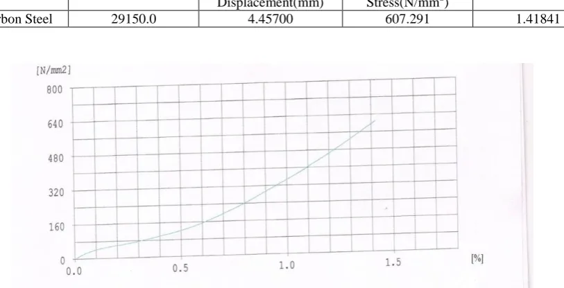
To find out tensile strength as well as Bending strength, we need to find out it directly from test or can be computed by property of material which is Modulus of Elasticity (E) value. So, for finding out value of Modulus of Elasticity (E) for all different material Blades, we conducted tensile test on all blades on Universal testing Machine (UTM). From obtained stress vs. Strain Graph , Value of Modulus of Elasticity (E) can be computed for all different materials and with help of Modulus of Elasticity (E) value , Bending strength can be analytically calculated.Values of Maximum load, Maximum Stress as well as Breaking load, Breaking Stress along with graph of intermediate points are as shown below:
Copyright to IJIRSET www.ijirset.com 2047
TABLE :2 STRESS- STRAIN VALUES FOR HCS BLADE
Sample ID Maximum Load(N) Maximum
Displacement(mm)
Maximum Stress (N/mm2)
Maximum Strain (%)
High Carbon Steel 29237.5 4.46800 609.114 1.41841
Sample ID Break Load(N) Break
Displacement(mm)
Break Stress(N/mm2)
Break Strain (%)
High Carbon Steel 29150.0 4.45700 607.291 1.41841
For Alloy Steel:
TABLE: 3 STRESS- STRAIN VALUES FOR ALLOY STEEL BLADE
Sample ID Maximum Load
(N)
Maximum Displacement(mm)
Maximum Stress (N/mm2)
Maximum Strain (%)
Alloy Steel 36712.5 4.44900 764.843 1.41238
Sample ID Break Load (N) Break
Displacement(mm)
Break Stress(N/mm2)
Break Strain(%)
Copyright to IJIRSET www.ijirset.com 2048
For Bi-Metallic:
TABLE: 4 STRESS- STRAIN VALUES FOR BI-METALLIC BLADE
Sample ID Maximum
Load(N)
Maximum Displacement(mm)
Maximum Stress(N/mm2)
MaximuStrain(%)
Bi-Metallic 43912.5 5.8600 914.843 1.86222
Sample ID Break Load(N) Break
Displacement(mm)
Break Stress(N/mm2)
Break Strain(%)
Bi-Metallic 43912.5 5.86600 914.843 1.86222
For High Speed Steel:
TABLE: 5 STRSS- STRAIN VALUES FOR HSS BLADE
Sample ID Break Load(N) Break
Displacement(mm)
Break Stress(N/mm2)
Break Strain(%)
High-Speed Steel 39037.5 5.32300 813.281 1.68984
Sample ID Maximum Load(N) Maximum
Displacement(mm)
Maximum Stress(N/mm2)
Maximum Strain(%)
Copyright to IJIRSET www.ijirset.com 2049
E. PERMISSIBLE DEFLECTION IN BUCKLING
Here, considering Hacksaw Blade as a long column, under Axial Loading, Hacksaw Blade will
Bend as shown in Figure 4.1, It Buckles in
the plane perpendicular to cutting.
e Here , Due to Axial Force P , Maximum Permissible
Deflection (e ) can be computed analytically.
With the help of maximum. Permissible Deflection, We Can find out maximum Permissible Crippling load
Or Critical load (Pcr)
For all Blades , Cross-sectional Area(A),Minimum Moment of Inertia and Section modulus (Z) will be same,
Moment of Inertia (minimum) for cross-section of blade, P Imin=
𝑏𝑑3
12 , where b= width of blade= 32 mm and d= thickness of blade= 6 mm
Imin = 576 mm 4
Cross section Area of Blade (A) = 32*6 = 192 mm2 Section Modulus, Z= Imin
𝑑/2 = 576
3 = 192 mm 3
Here Radius of Gyration (k) k= 𝐼
𝐴 = 1.732
and Slenderness ratio(l/k) = 230.94 > 100 so, Euler’s formula can be applied.
For 1) High Carbon Steel Blade :- (Sample Calculation)
From Data obtained by Tension Test on UTM Machine , value of Modulus of Elasticity (E) can be obtained with the help of graph.
Here , Stress σ1 = 160 MPa Stain, ε1 = 0.00612 ,
σ2 = 609.114 MPa ε2 = 0.0142
Now , Modulus of Elasticity (E) = σ2 − σ1
ε2−ε1 =
609.114 −160
0.0142 −0.00612 = 55.58 * 10 3
MPa By Euler’s formula, Critical load or Crippling load (Pcr)
Pcr=
𝑛 𝜋2𝐸 𝐼𝑚𝑖𝑛
𝐿2 , where L= length of blade= 400 mm , n=1 (both ends hinged)
So, Pcr= 1972.79 N
Now, Bending moment (M) = fc * Z = Pcr* emax
Assuming fc for steel material = 300 MPa,
Bending moment (M) = 57600 N mm
So, Maximum Permissible Deflection emax=29.2 mm
Deflection (e) 10 15 20 25 29.2
Crippling load (P) 5760 3840 2880 2304 1972.79
Similarly, other calculations can be done for different material of blades.
III. RESULT DISCUSSION
The following points from the tests we have carried out on different materials for the hack-saw blades.
Hardness test:
High speed steel blade and alloy steel blade having hardness of order of 65 HRC is higher than other materials. Hence, HSS is the best as far as the hardness of tooth is concerned. So, for cutting harder work piece like mild steel etc., best option is to employ HSS material blade.
Copyright to IJIRSET www.ijirset.com 2050 In Bi-metallic strip blade, as only teeth are being hardened, hardness remains almost the same including both
ends. The ends are not annealed because punch are made on relative softer shank material.
In low alloy and HSS blades, the hardness throughout remains almost constant except two ends as ends are being annealed for easy installation. Also variation in hardness along the length of blade is more in case of alloy steel blade compared to HSS blade.
Hardness of high carbon steel is lower than other materials. Therefore, this kind of blade is used only to cut softer material lxike copper, brass, aluminum etc.
Cutting performance
High carbon steel blade is mainly used to cut the brass material as time for cutting of Brass material by High carbon steel blade is the least. So, the materials like brass, copper, bronze etc. are efficiently cut with high carbon steel as far as time is concerned. For ferrous materials it takes lot of time to cut.
Alloy steel blades are used to cut the non-ferrous materials like brass, aluminium etc. as they take lower time for cutting of non-ferrous materials.
Bi-metallic blades are the best to cut the ferrous materials like mild steel etc. as far as the cutting time is concerned. Also for non-ferrous materials it gives good performance.
HSS blades cut both ferrous as well as non-ferrous materials with minimum cutting time.
Wear test
The high carbon steel experiences minimum wear on tooth for cutting the aluminium, gun metal etc.
The brass material and other non-ferrous materials can be cut with alloy steel and high carbon steel for the minimum amount of wear.
For cutting ferrous materials like mild steel, HSS as well as Bi-metallic blades experience lower wear whereas alloy steel blades experience highest wear for cutting ferrous materials.
So, for cutting ferrous materials HSS and Bi-metallic blades are best in wear consideration also for cutting non-ferrous materials either high carbon steel or alloy steel is good as far as the wear is concerned.
Tensile test
Bi-metallic and HSS blades are having higher tensile strength of the order of 900 MPa whereas high carbon steel blades is having tensile strength of the order of 600 MPa and alloy steel is having of the order of 750 MPa.
So, HSS and Bi-metallic blades are superior as far as the tensile strength is concerned.
Performance under Buckling
HSS and low carbon steel blades are having maximum deflection of the order of 30 mm while Bi-metallic and alloy steel blades are having of the order of 28 mm. So, HSS blades are better under buckling than others.V.
C
ONCLUSIONProperties of Material:
High carbon steel Alloy steel Bi-metallic strip High speed steel
Hardness Fair Good Better Best
Tensile strength Fair Good Best Better
Response under Buckling
Better Fair Good Best
From the above table, it is concluded that High speed steel (HSS) has overall good properties compared to other materials of blade.
Cutting Performance:
High carbon steel Alloy steel Bi-metallic strip High speed steel
Alluminium Fair Better Best Good
Brass Best Better Fair Good
Copyright to IJIRSET www.ijirset.com 2051
From the Cutting Performance, it is indicated that Bi-Metallic Strip is good to cut the Alluminium& Mild steel, High Carbon Steel is good to cut Brass material.
Wear Resistance:
High carbon steel Alloy steel Bi-metallic strip High speed steel
Alluminium Best Better Good Fair
Brass Better Best Fair Good
Mild steel Good Fair Better Best
From the Wear Resistance , it is indicated that High Carbon Steel experiences less wear for Alluminium, like Alloy steel for Brass and HSS for Mild steel.
REFERENCES
[1] B.S.Raghuvanshi, “ Workshop Technology”, vol II, ,Dhanpatrai & sons, 1989, Delhi-6. [2] Production Technology by HMT, Tata McGraw-Hill Education, 2001, Banglore. [3] R.K.Jain, “Production Technology”, 13th Edition, Khanna Publisher,1993, Delhi.
[4] T.V.Rajan, C.P.Sharma, Ashok Sharma, “Heat Treatment Principles and Techniques” ,
Prentice Hall of India Private Limited,1998, New Delhi.
[5] Roger R. Brockenbrough, P.E., President R.L.Brockenbrough & Accociates , “Properties of Structural Steels and Effects of Steel Making andFabrication” Chapter 1. Pitsburgh, Penssylvenia.
[6] R.S.Khurmi & J.K.Gupta text book of “Machine Design”, first edition, S.Chand, Eurasia Publishing house, New delhi, India.
A
CKNOWLEDGEMENTWe would like to express our sincere thanks and gratitude to PROF. NITINCHANDRA R. PATEL (Department of Mechanical Engineering) of G.H.Patel college of Engineering & Technology, VallabhVidyanagar for devoting much of his precious and valuable time during the entire research work and for offering numerous suggestions and encouragement thus making this project possible
RAVI A THAKKAR (ENRL. NO: 090110119004) BALKRUSHNA B JANI (ENRL. NO: 090110119011) MITESHKUMAR D RATHWA (ENRL. NO: 090110119049) MOHAMMED A VASANWALA (ENRL. NO: 090110119057)
BIOGRAPHY
Prof. Nitinchandra R. Patel is an Assistant Professor in Mechanical Engineering department of G. H. Patel College of Engineering & technology, Vallabh vidyanagar, Gujarat, India. He completed Master degree in Machine Design in 2004 from Sardar Patel University, Vallabh vidyanagar and Bachelor degree in Mechanical Engineering in 1997 from B.V.M. Engineering College, Sardar Patel University. He has 5 years working experience in Industries and 11 years in Teaching. He is a member of ASME, Associate member of Institute of Engineers (I) and Life member of ISTE. He is also recognized as a Chartered Engineer by Institute of Engineers (I) in Mechanical Engineering Division.
Mohammed Vasanwala is a Final year student of Bachelor degree in Mechanical Engineering department of G H. Patel college of Engineering & technology, Vallabh vidyanagar.
Copyright to IJIRSET www.ijirset.com 2052
Balkrushna B. Jani is a Final year student of Bachelor degree in Mechanical Engineering department of G H. Patel college of Engineering & technology, Vallabh vidyanagar.
Miteshkumar D. Rathwa is a Final year student of Bachelor degree in Mechanical Engineering department of G H. Patel college of Engineering & technology, Vallabh vidyanagar.
Ravikumar A. Thakkar is a Final year student of Bachelor degree in Mechanical Engineering department of G H. Patel college of Engineering & technology, Vallabh vidyanagar.