Nonlinear Spatial Localized Strain Waves
Vladimir I. Erofeev1,2*, Sergey I. Gerasimov2, and Alexey O. Malkhanov2
1Research Institute for Mechanics, National Research Lobachevsky State University of Nizhni Novgorod, 23, Gagarin av.,
Nizhny Novgorod, 603950, Russia
2Mechanical Engineering Research Institute of Russian Academy of Sciences, 85, Belinskogo st., Nizhny Novgorod, 603024, Russia
Abstract. A possible way of study of single waves in solids is discussed. The soliton is one of these waves without shape and parameters varying. Soliton deformation parameters are connected with the elastic moduli of the third order that allows defining values of these moduli by means of the measured soliton-deformation parameters in various type waveguides made of the same material. The conditions under which a soliton can exist in a rod are analytically determined. For simultaneous excitation of loading in several wave guides two new energetic photosensitive structures (the mixtures are given) initiated by means of short light impulses of noncoherent light sources are proposed. Conditions of excitation of the waves on the basis of multipoint optical initiation loading impulses are described. As a technique for registration the shadowgraph visualization is proposed. It is discussed, how the problem connected to the use of energetic initiation structures consisting in the power background illumination can be solved. The shadow scheme with the use of a tiny dot explosive light source (Тbr ~41 kK) allows to carry out modelling experiments on research of slabbing actions, jet formations, fluffings, hydrodynamic instability during shock-wave loading of investigated samples, which makes it attractive for determination of parameters in equations-of-state for investigated materials, creation of numerical models and their validation. Some examples showing basic possibility of application of the declared techniques are included.
1 Introduction
In 1895 Kortweg and de Vries published the equation describing waves on the surface of shallow water [1]:
2
33=
0
∂
∂
+
∂
∂
+
∂
∂
x
u
d
x
u
bu
t
u
that has a solution corresponding to the Russell's solitary wave in the limit:
6
k
2ch
2k
(
x
4
dk
2t
)
b
d
u
=
−−
the wave number k is an arbitrary parameter.
At the physical point of view, nonlinearity and dispersion are counterbalanced in this wave what leads to occurrence of a steady formation – a single bell-shaped wave which propagates on large distances without shape and speed changes and which has received the name of "soliton".
The question of a big practical interest refers to possibility of oscillation and observation of a long solitary wave of deformation in a solid-state waveguide. First, soliton deformation parameters are connected with the elastic moduli of the third order that allows to define values of these moduli by means of the measured soliton deformation parameters in various type wave guides
made of the same material. Secondly, it demands a solution of a variety of the problems connected with oscillation of such waves and techniques for their registration.
A possibility of oscillation and the following propagation of the nonlinear wave keeping its shape and speed in ordinary conditions of a modern physical laboratory observation has been shown in the article [2]. A pulsing ruby radiation laser would cause an instant evaporation of metal on a film placed together with a rod in a pan with water, and the shock wave generated in the water would get into the rod at the experiment. Two-exposition holographic interferogram shooting allowed to fix a solitary nonlinear wave with almost not varying parameters and the shape.
Besides the desire to repeat the received result with possibility of better visualization, it would be desirable to simplify the given technique and to raise its functionality. The present work serves this purpose and describes approachability of some positions of the new developed technique for registration of compression waves in solids. The primary goals reached by means of the new technique are:
- simultaneous excitation of disturbances in a number of solid-state waveguides;
- qualitative visualization of oscillated waves and possibility of opaque materials use.
By this statement, it is possible at the same experiment to observe distinction in behaviour of the waves in waveguides with various geometry (for example, in those that have variable cross-section for strengthening or attenuation of the wave or in those that have contact with external medium of the ordered material and of the ordered sizes), waveguides from various materials, and, also, to use separate waveguides for data acquisition on parameters of the wave by means of pressure gauges, etc.
The assessment for the range of values for the ordered initial loading impulse is carried out on the basis of the equation for longitudinal waves in a rod with the free lateral surface [3, 4, 5]. Considering the nonlinearity, the equation with two dispersion items for the function of longitudinal deformation u = Ux is:
0 4 4 3 2 2 4 2 2 2 2 1 2 2 2 0 2 2 = ∂ ∂ ⋅ − ∂ ∂ ∂ ⋅ + ∂ ∂ ⋅ − ∂ ∂ ⋅ − ∂ ∂ x u t x u x u x u c t
u α α α (1)
where
0
2 0 ρE
c =
,
E=µ⋅(
3λ⋅λ++µ2⋅µ)
The expressions for the dispersive items
α
2 andα
3 for the Kirchhoff-Love model within the limits of the hypothesis of the flat sections are [4]:2 R2 2 2=−ν ⋅
α
,
0 2 2
3
ν
2µ
ρ
α
⋅ ⋅ ⋅ − = Rfor the Murnaghan five-constant model [5] are:
(
)
2 R
1 2
2 =ν⋅ −ν ⋅
α
,
0 2
3
ν
2ρ
α
⋅ ⋅ ⋅
= E R
where R – rod’s radius.
The coefficient of nonlinearity β in the item
0 1
2
β
ρ
α
⋅
=
is defined through Murnaghan’s moduli of the third order:β
=3⋅E+2⋅ ⋅(
1−2⋅ν
)
3+4⋅m⋅(
1−2⋅ν
) ( )
⋅1+ν
2+6⋅n⋅ν
2
The equation (1) has the exact solution in the form of a running solitary wave Ach-2((x-Vt)/λ) and for two models listed above looks like:
5 . 0 2 2 0 2 2 0 2 5 . 0 0 2 2 2 2 0 2 2 1 2 0 2 ) ) ) 1 ( ( 2 ( ] 4 [ ) ) / ( 2 ( ] 3 , 2 [ where , )) ( ( 2 ) ( 3 V c R c V k V R c V k Vt x k ch c V u ν ν ρ µ ν α − − − = − − = − − = −
Hence, for a soliton to exist at the positive Poisson’s coefficient in the range 0<ν<0.5, it’s speed of propagation in a rod should be supersonic (V>c0) in all the models and lay in the range c0 <V <c0/(1-ν)0.5, according to [4], and out of the range 0 <V <( / ρ0)0.5, according to [2, 3].
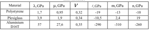
Some data on moduli of elasticity of the third order are presented below (see table 1).
Table 1.Lame’s modulus λ, Poisson’s coefficient ν and Murnaghan’s moduli of the third order for some elastic
materials.
Material λ,GPa µ,GPa
ν
,GPa m,GPa n,GPa Polystyrene 1,7 0,95 0,32 -19 -13 -10Plexiglass 3,9 1,9 0,34 -10,5 2,4 19 Aluminium
D16T 57 27,6 0,35 -290 -310 -260
2 Multipoint shock wave oscillation in a
rod
For simultaneous loading of several waveguides, it is possible to apply the initiation of caps-detonators from one blasting generator. The drawback of this technique consists in power loading impulses which would lead to slabbing destruction of the tested samples. The variation of loading impulse parameters can be carried out by use of new energetic photosensitive structures initiated by means of short light impulses of noncoherent light sources [6]. The photosensitive energetic materials are:
the pyrotechnic structure VS-1: a solid powdery
substance of green color (two tones are supposed), represents the mixture of perchlorate 3 (5) - gidrazino-4-amino-1,2,4-cuprumtriazol (II) (~90 %) with optically transparent energy-saturated copolymer 2-metil-5-viniltetrazol (~98 %) and methacrylic acid (~2 %) (TU 38-403-208-88) (~10 %); an explosion-dangerous and sensitive to mechanical shock material that has the following characteristics: flash temperature (by OST B 84-1583-78) ~ 230 0С, sensitivity to blow in accordance to GOST (the RF state standard) 4545-88 (the test set
№1, cargo of 2 kg) – not more than 12 %; and the
pyrotechnic structure VS-2: a solid powdery substance
of white color (two tones are supposed), represents the mixture of (5-gidrazinotetrazol) mercury (II) perchlorate (~90 %) with optically transparent energy-saturated copolymer 2-metil-5-viniltetrazol (~98 %) and methacrylic acid (~2 %) (TU 38-403-208-88) (~10 %); an explosion-dangerous and sensitive to mechanical shock material at the level of power brisant explosives. The given structure has the following characteristics: flash temperature by OST B 84-1583-78 ~ 185 °С, sensitivity to blow in accordance to GOST (the RF state standard) 4545-88 (the test set №1, cargo of 2 kg) – not more than 12 %, the bottom limit in the test set № 2 is 50 mm.
Synchronism of VS-2 initiation was checked up in a series of experiments, the scheme of which is presented
in Figure 1. A group of brass caps (diameter – 5 mm,
radiator connected to an operated accumulative devise of the electric energy (150 J, 15 kV) [7]. Control of the accumulative device triggering was realized by means of a triggering time delay unit which after delivery of the “Start” signal to the accumulative device at the moment of time t provided the start of the x-ray device "MIRA-3D" at the moment t+∆t. The intervals for shooting time
∆t in four experiments got out the equal 0, 5, 10, 30 µs after the moment of light impulse generating.
Fig. 1. The scheme of radiographic researches. 1 – x-ray device; 2 – x-ray device control panel;3 – triggering time delay unit; 4 – operated accumulative device; 5 – cartridge with a radiographic film; 6 – lead mask-absorber; 7 – radiator; 8 – a group of caps with VS-2 (5 pieces).
The distance between the x-ray device and the object of shooting to the distance between object of shooting and the film ratio was 2.38 that provided zoom-index К=1.42. The thickness of the contrast mask-absorber – 5 mm, the size of the window – 60×120 mm. The x-ray pictures received are given in Figure 2. With these images, it is possible to conclude that in the range of shooting time (0≤∆t≤30 µs which obviously overlaps the period of transfer of detonation from pyrotechnic structure to the secondary charge) thrown by the products of detonation of the pyrotechnic structure caps bottom sides do not disperse from the common for them all flat surface of their initial installation on the distance of 0.5 mm (the thickness of the bottom side). At the account that the speed of cuprum perclorate detonation equals to 6 mm/µs, and at the account that its decrease provided by the addition of phlegmatizer is not more than twice, the expected "upper bound" of product work time difference lays within the limits ∆
τ
=±0,17 µs that could be admitted as a satisfactory result for application in majority of gasdynamic schemes.Fig. 2. Results of radiographic research witnessing the synchronism of VS-2.
The achievable 0,5 GPa level proves to be true by the fact of detonation initiation in the bulk TNT contacting to a cap with VC-2. The level of the loading impulse is varied by reducing the thickness of the initiated photosensitive layer (to 0,1 mm).
3 Optical techniques of registration
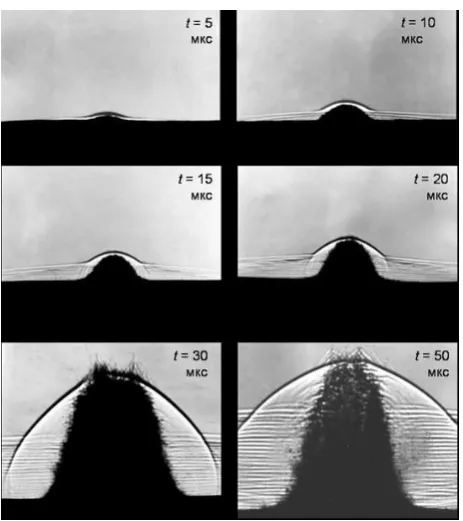
The basic problem connected with the use of energetic initiation structures consists in the power background illumination that is capable to bring restrictions to shadowgraph techniques of registration. We developed some shadowgraph schemes allowing using large-format ortochromatic films with sensitivity of some units of GOST during explosive loading of investigated samples [8, 9]. High resolution of the scheme (more than 300 lin/mm) and capability of optical heterogeneity visualization allow registering the wave process of the investigated phenomena at the moment of registration, i.e. the shock-wave circulation in the material, that is appearig as strong oscillation at corresponding disrupture on the border of the free metal surface and the air. The shadow scheme with the use of a tiny dot explosive light source with Тbr ~41 kK allows to carry out modelling experiments on research of slabbing actions, jet formations, fluffing, hydrodynamic instability during shock-wave loading of investigated samples, which makes it attractive for determination of parameters in equations of state for the investigated materials, carrying out and testing numerical techniques. Specific shadowgraphs of explosive loading of a steel 5 mm plate at different moments of time are demonstrated in Figure 3. The features of the process – fluffing, oscillation of the free surface, splitting of the first shock wave, luminescence of the disturbed air behind the shock wave are well visualized. Figure 4 shows the process at a later moment of time.Fig. 3. Dynamics of the fixed steel plate (thickness of 5 mm, rough surface) (loading time in µs is counted from the moment of initiation of the cap-detonator mounted under the plate through 1-mm layer of plastic structure on the basis of fine powdered TNT).
Fig. 4. A shadowgraph of the process (see Figure 3) at the moment of time t=209 µs.
Fig. 5. Simultaneous loading of a steel plate by three simultaneously initiated cap-detonators placed in a line.
A shadowgraph of shock-wave loading of transparent objects allows visualizing optical heterogeneity at the moment when the disturbances go out on the border of the loaded body with the air and, simultaneously, the zones of transparency loss in the body. Figure 6
demonstrates the photo of simultaneous edge loading of
samples from plexiglass (on the right) and LiF at the moment of 3,1 µs by means of electrodetonators. The samples are columns by height of 27,5 mm with rectangular cross-section (15x10 mm). As for Figure 7, simultaneous loading of plexiglass parallelepipeds with the sizes (55x55x10 mm) and (55x10x10 mm) by means of electrodetonators is shown. The detonators contacting with the centre of the bottom side of the samples were mounted from below. In the plane nearest to the film the grid (10x10 mm) was marked on the samples.
Fig. 6. Simultaneous explosive loading of samples from plexiglass (on the right) and LiF (3.1 µs).
4 Conclusions
Elements of the shadowgraph visualization technique allowing investigating wave flows at the presence of power background illuminations and at simultaneous loading of several tested samples are developed. It is proposed to use the given technique for study of solitary compression waves in various materials.
This work was supported by a grant from the Government of the Russian Federation (contract No. 14.Y26.31.0031).
References
1. D.J. Korteweg, G. de Vries. On the change of shape of long waves advancing in a rectangular canal and on a new type of long stationary waves. Phil. Mag.,
39 (240) (1895)
2. G.V. Drejden, A.V. Porubov, A.M. Samsonov, I.V. Semenova, E.V. Sokurinskaja. Experiments in the propagation of longitudinal strain solitons in a nonlinearly rod. Tech. Phys. Lett., 21, 415 (1995) 3. A.M. Samsonov. On existence of longitudinal strain
solitons in an infinite nonlinearly elastic rod. Sov. Phys.-Doklady. 33, 298 (1988)
4. V.I. Erofeev, N.V. Klyueva. Solitons and nonlinear periodic strain waves in rods, plates and shells (a review). Acoust. Phys. 48(6), 643 (2002)
5. A.V. Porubov. Amplification of Nonlinear Strain Waves in Solids. Singapore: World Scientific, (2003)
6. S. Gerasimov, M. Iliushin, A. Len. Definition of diversity for ignition of light-sensitive pyrotechnic composition pellets with roentgraph method. Proceedings of the 14th seminar of New Trends in Research of Energetic Materials. University of Pardubice. Pardubice, Czech Republic, April 13-15, Part I (2011)
7. S.I. Gerasimov, J.I. Fajkov, S.A. Holin. Cumulative sources of light. Second edition. Sarov, FGUP "RFJATS-VNIIEF" (2011)
8. S.I. Gerasimov. Diagnostics at research of the effects accompanying an exit of a shock wave on a free surface while shock-wave loading. The Nonlinear World, 7 (2009)