Forward Kinematic Analysis, Simulation &
Workspace Tracing of Anthropomorphic
Robot Manipulator By Using MSC. ADAMS
Amit L Talli
1, B. B. Kotturshettar
2Asst. Professor, Department of Automation & Robotics Engineering, B.V. Bhoomaraddi College of Engineering and Technology, Vidyanagar, Hubli, Karnataka, India 1
Professor, Department of Industrial and Production Engineering, B.V. Bhoomaraddi College of Engineering and Technology, Vidyanagar, Hubli, Karnataka, India 2
ABSTRACT: The Robot kinematics deals with the position of links which are connected with the help of joints, which
gives the position and orientation of every link present in the robot manipulator to place the end-effector to the required target. A kinematic model of the anthropomorphic robot manipulator was developed using multibody dynamic software called MSC. Automated Dynamic Analysis of Mechanical Systems (ADAMS) which represents the human arm. The shoulder joint is considered as spherical joint and elbow joint as a revolute joint. Kinematic equations and Software model is developed to compare and verify the working of the robot manipulator. The Workspace of the robot manipulator was traced to show the maximum and minimum working area of the manipulator. The workspace of the robot manipulator is traced in MSC. ADAMS to show the working region of the manipulator.
KEYWORDS:Anthropomorphic, End-effector, Forward Kinematics, MSC. ADAMS, Workspace.
I. INTRODUCTION
A manipulator can be schematically represented from a mechanical viewpoint as kinematic chain of rigid bodies (links) connected by means of revolute or prismatic joints. One end of the chain is fixed to a base, while an end-effector is attached on the other end [1].
Robot arm kinematics deals with the analytical study of the geometry of motion of a robot arm with respect to a fixed reference coordinate system as a function of time without regard to the forces / moments that cause the motion [2]. Kinematic equation gives the relationship between the joint displacement and the position and orientation of end-effector is determined. Determining the final position & orientation of the end end-effector depending upon the joint angles is known as forward kinematics and finding the joint angles depending upon the position of end effector is known as inverse kinematics [3].
An end effector is a device that attaches to the wrist of the robot arm and enables the general – purpose robot to perform a specific task. It is sometimes referred to as robot‟s “hand” [4].
In robotics, end effectors are fixed /attached to the robot arm, which interacts with the surroundings like a human hand having fingers to lift or grab. Gripper is an end effector or tool to grab any object or any tools, which can be used for welding, painting etc. The gripper performs tasks such as picking, grasping or holding by various means for different applications [5].
The MSC. ADAMS software is capable of simulating kinematics and kinetics behaviour of any mechanical system. The dynamic behaviour of a system can be compared with the real models that can be simulated with an acceptable variation in the result [7]. MSC. ADAMS software tool plays very important tool for rapid virtual prototyping which reduces the design failure or feasibility of the design. Real prototype model takes lots of time to test because it needs testing setup and environment. MSC. ADAMS incorporates all the required dynamics virtually which is required for real testing conditions. Various modeling files can be imported in MSC. ADAMS from SolidWorks, Creo, Catia or Solidedge etc. [8].
II. RELATEDWORK
The robot manipulators are classified depending upon their configuration, such as Cartesian robot, Cylindrical robot, Spherical robot, SCARA robot, Articulated robot, Parallel robot. These robots consist of revolute joint or prismatic joints to meet the desired motion. The revolute and prismatic joints are very simple and are not complicated to use. These joints have one degree of freedom, so that linear motion is achieved in case of prismatic joint and rotary motion is achieved in case of revolute joints. Kinematic analysis, Simulations is performed by using MATLAB simulink or sometimes VRML (Virtual Reality Modeling Language) is used to carry out analysis part. This paper deals with a new robot manipulator, which uses a spherical joint. Spherical joints are very complex in nature due to its number of degrees of freedom. Sometimes it becomes necessary to deactivate at least one degree of freedom to avoid redundancy error. This robot manipulator closely resembles the functions of a human arm. The kinematic equations are developed and verified in MSC. ADAMS by comparing the analytical results and software results.
III.METHODOLOGY
The block diagram represents the step by step methodology for the kinematic analysis, simulation and workspace tracing robot manipulator is shown in Figure 1.
Fig.1 Flow chart of Methodology
III.1ANTHROPOMORPHIC DATA COLLECTION
Anthropometry in physical anthropology refers to the measurement of the human individual for the purposes of understanding human physical variation. The anatomy of human arm is shown in Figure 2.
Anthropometric Data Collection
Design Simulation
Anthropometric dimensions selected for upper arm and forearm for the robot manipulator are [9]: L1 = 310 mm or
0.31m and L2 = 280 mm or 0.28 m.
III.2ANATOMY OF ANTHROPOMORPHIC MANIPULATOR
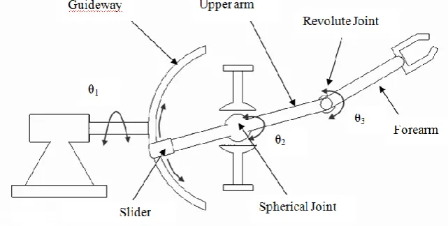
The model of 3 DOF robot manipulator is shown in Figure 3. The diagram of robot manipulator is similar to human arm. The robot has total two joints i.e. one spherical joint and one revolute joint. The revolute joint connects between upper arm and forearm, the spherical joint connects upper arm and actuator (guideway, motor etc). The spherical joint plays very important role in this model. The end-effector is located at the end of forearm which is similar to wrist end.
Fig.3 Anatomy of Robot Manipulator
III.3WORKING PRINCIPLE OF ANTHROPOMORPHIC MANIPULATOR
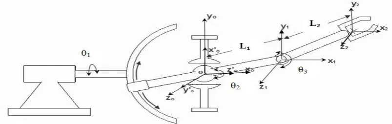
The 3-DOF robot manipulator has one spherical joint and one revolute joint. The spherical joint is supported by the cups which are fixed or grounded. Behind the spherical joint a link is extended as a slider which slides along the guideway. The guideway is connected to the motor shaft which is located behind the guideway as shown in the above figure. The joint connecting the forearm and upper arm is called revolute joint which is also called as elbow joint in human anatomy. The joint can rotate the forearm in upward or in a downward direction. When the motor rotates in clockwise/counter clockwise direction, the guideway which is connected to the motor also rotates so that the upper arm and forearm also rotates in clockwise/counter clockwise direction. When the slider moves along the guideway which is in the shape of an arc, the upper arm and forearm also moves in up and down directions. The 3-DOF robot manipulator is shown in Figure 4. θ1, θ2, θ3 are motor rotation angle, Upper arm rotation angle and Forearm rotation angle.
III.4 MODEL OF ANTHROPOMORPHIC ROBOT MANIPULATOR
A virtual model of robot manipulator built in MSC. ADAMS software package interface of MSC. ADAMS is shown in Figure 5.
Fig.5 Model of Robot Manipulator in MSC. ADAMS
III.5FORWARD KINEMATIC EQUATIONS
The Forward kinematic equations are developed based on Denavit – Hartenberg parameters [10]. The coordinate frames are identified base on the three criteria:
a) The zi-1 axis lies along the axis of motion of the i th
joint. b) The xi axis is normal to the zi-1 axis, and pointing away from it.
c) The yi axis completes the right – handed coordinate system as required.
From above rules, the location of coordinate frame „0‟ is assigned for the supporting base, as long as the z0 axis lies
along the axis of motion of the first joint.
The last coordinate frame (nth frame) can be placed anywhere in the hand, as long as the xn axis is normal to the zn-1 axis
The D-H representation of a rigid link depends on four geometric parameters associated with each link. The four parameters are defined as follows [11]:
1) θi is the joint angle from the xi-1 axis about the zi-1 axis.
2) di is the joint distance along the zi-1axis.
3) ai is the offset distance from the intersection of the zi-1 axis with the xi axis to the origin of the ith frame along
the xi axis (or the shortest distance between the zi-1 and zi axes).
4) αi is the offset angle from the zi-1 axis to the zi axis about the xi axis.
The Joint-Link parameters are identified and these are tabulated in Table 1.
Table -1 Joint-Link Parameters for 3-DOF Robot Manipulator
T = T (z, θ1) ∗ T (z, α1) ∗ T (z, θ2) ∗ T (z, θ3) (1)
T= 𝐶1 −𝑆1 0 0 𝑆1 𝐶1 0 0 0 0 1 0 0 0 0 1 1 0 0 0 0 𝐶𝛼 −𝑆𝛼 0 0 𝑆𝛼 𝐶𝑆 0 0 0 0 1 (2)
T= 𝐶1 −𝑆1 0 0 𝑆1 𝐶1 0 0 0 0 1 0 0 0 0 1 1 0 0 0 0 0 1 0 0 −1 0 0 0 0 0 1 (3) T= 𝐶1 0 −𝑆1 0 𝑆1 0 𝐶1 0 0 −1 0 0 0 0 0 1 𝑆2 𝐶2 0 𝐿2𝑆2 −𝐶2 𝑆2 0 −𝐿1𝐶2 0 0 1 0 0 0 0 1 𝐶3 −𝑆3 0 𝐿2𝐶3 𝑆3 𝐶3 0 𝐿2𝑆2 0 0 1 0 0 0 0 1 (4)
T = 𝐶1 0 −𝑆1 0 𝑆1 0 𝐶1 0 0 −1 0 0 0 0 0 1 𝑆2𝐶3+ 𝐶2𝑆3 −𝑆2𝑆3+ 𝐶2𝐶3 0 𝑆2𝐿2𝐶3+ 𝐶2𝐿2𝑆3+ 𝐿1𝑆2 −𝐶2𝐶3+ 𝑆2𝑆3 𝐶2𝑆3+ 𝑆2𝐶3 0 −𝐶2𝐿2𝐶3+ 𝑆2𝐿2𝑆3− 𝐿1𝐶2 0 0 1 0 0 0 0 1 T = 𝐶1𝑆2𝐶3+ 𝐶1𝐶2𝑆3 −𝐶1𝑆2𝑆3+ 𝐶1𝐶2𝐶3 −𝑆1 𝐶1𝑆2𝐿2𝐶3+ 𝐶1𝐶2𝐿2𝑆3+ 𝐶1𝐿1𝑆2 𝑆1𝑆2𝑆3+ 𝑆1𝐶2𝑆3 −𝑆1𝑆2𝑆3+ 𝑆1𝐶2𝐶3 𝐶1 𝑆1𝑆2𝐿2𝐶3+ 𝑆1𝐶2𝐿2𝑆3+ 𝐿1𝑆1𝑆2 𝐶2𝐶3− 𝑆2𝑆3 −𝐶2𝑆3− 𝐶2𝐶3 0 𝐶2𝐿2𝐶3− 𝑆2𝐿2𝑆3+ 𝐿1𝐶2 0 0 0 1 𝑥 = 𝐶1𝑆2𝐿2𝐶3+ 𝐶1𝐶2𝐿2𝑆3+ 𝐶1𝐿1𝑆2 (5)
𝑦 = 𝑆1𝑆2𝐿2𝐶3+ 𝑆1𝐶2𝐿2𝑆3+ 𝐿1𝑆1𝑆2 (6)
𝑧 = 𝐶2𝐿2𝐶3− 𝑆2𝐿2𝑆3+ 𝐿1𝐶2 (7)
𝑥 = 𝑆2𝐿2𝐶3+ 𝐶2𝐿2𝑆3+ 𝐿1𝑆2 𝐶1 (8)
𝑦 = 𝑆2𝐿2𝐶3+ 𝐶2𝐿2𝑆3+ 𝐿1𝑆2 𝑆1 (9)
𝑧 = 𝐿1𝐶2+ 𝐿2cos 𝜃2+ 𝜃3 (10)
∴
The position of end-effector is obtained from the following equations𝑃𝑥= 𝐿1sin 𝜃2+ 𝐿2sin 𝜃2+ 𝜃3 cos 𝜃1
(11)
𝑃𝑦 = 𝐿1sin 𝜃2+ 𝐿2sin 𝜃2+ 𝜃3 sin 𝜃1 (12)
𝑃𝑧 = 𝐿1cos 𝜃2+ 𝐿2cos 𝜃2+ 𝜃3 (13)
IV.RESULTS&DISCUSSIONS
IV.1COMPARISON BETWEEN ANALYTICAL & MSC. ADAMS RESULTS
θ1 (Motor rotation) is kept zero i.e. no motion, whereas θ2 (Upper arm angle) & θ3 (Forearm angle) are varied up to 70°
and 140°. The position of end-effector for various joint variables is determined analytically & from MSC. ADAMS software tool are shown in Table 2 and 3. θ1= zero (constant), θ2 = varies 10° (up to 70°), θ3 = varies 20° (up to 140°)
Px, Py, Pz are in „mm‟ & θ1, θ2, θ3 are in degrees. Manipulator moving up (while moving up joint angles are taken as
positive)
Joint i θi αi ai
1 θ1 -90˚ 0
2 θ2 0 L1
Table-2: Iteration of Robot Manipulator For θ1=0˚, θ2=10˚ to 70˚ & θ3=20˚ to 140˚
Joint angles Analytical Results MSC. ADAMS Results Error θ1 θ2 θ3 Px Py Pz Px Py Pz
0 10 20 193.830 0 547.777 193.830 0 547.777 0 0 20 40 348.513 0 431.304 348.513 0 431.304 0 0 30 60 435.0 0 268.467 435.0 0 268.467 0 0 40 80 441.75 0 97.473 441.75 0 97.473 0 0 50 100 377.473 0 -43.222 377.473 0 -43.223 0.001 0 60 120 268.467 0 -125.0 268.467 0 -125.0 0 0 70 140 151.304 0 -136.460 151.304 0 -136.460 0
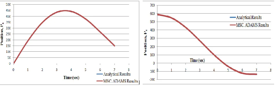
Graphical comparison between analytical & MSC. ADAMS results are shown in Figure 7 and Figure 8. The values of position of end-effector, Px in „mm‟ and Pz in „mm‟ from Table 2 are plotted graphically. The values obtained from analytical method and MSC. ADAMS results are same due to which the two curves overlap. The x-axis is simulation time and y-axis is position. Blue colour curve indicate analytical results and red colour curve indicate MSC. ADAMS results.
Fig. 7 Graphical Plot of Position Px against Time Fig. 8 Graphical Plot of Position Pz against Time
IV.2WORKSPACE TRACING
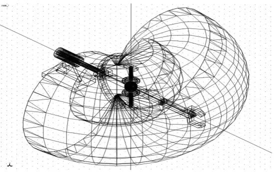
Figure 12 represents the wireframe view of workspace of the manipulator.
Fig. 12 Wireframe view of workspace of robot manipulator
V. CONCLUSION
A complete virtual model of 3 Degrees of Freedom robot manipulator is developed by using anthropometric data. Simulation of the model was performed by using MSC. ADAMS. All desired motions were achieved by using a spherical joint in robot configuration. The results obtained from analytical and MSC. ADAMS are same and validates the developed equations. Workspace profile of the robot manipulator was traced to show the profile of working region of manipulator. The performance and feasibility of the design of robot manipulator can be checked using MSC. ADAMS before going for physical model which is time consuming process.
REFERENCES
1. Lorenzo Sciavicco, Luigi Villani, “Robotics: Modelling, Planning and control”, Springer, pp. 39 – 45, 2008.
2. K S Fu, Ralph Gonzalez, C S G Lee, “Robotics: Control, Sensing, Vision, and Intelligence”, Tata McGraw-Hill, pp. 12 – 20, 2008.
3. Jolly Atit Shah, S.S. Rattan, B.C. Nakra, “End-Effector Position Analysis Using Forward Kinematics For 5 DOF Pravak Robot Arm”, International Journal of Robotics and Automation (IJRA), Vol. 2, No. 3, pp. 112-116, September 2013.
4. Mikell P. Groover, Mitchell Weiss, Roger N. Nagel, Nicholas G. Odrey, “Industrial Robotics Technology, Programming, and Applications”, Tata McGraw-Hill, pp.116 – 140, 2008.
5. Puran Singh, Anil Kumar, Mahesh Vashisth, “Design of a Robotic Arm with Gripper & End Effector for Spot Welding”, Universal Journal of Mechanical Engineering, 1 , 92 - 97, 2013.
6. Hansen J.A., Gupta K.C., Kazerounian S.M.K., “Generation and evaluation of the workspace of a manipulator”, The Int. J. Of Robotics Research, Vol. 2(3), pp.22-31, 1983.
7. V Vennishmuthu , S.Riyaz Ahammed, R.Hushein, Karthik.P, “Stability Simulation of Six DOF manipulators using ADAMS and MATLAB”, IOSR Journal of Engineering (IOSRJEN), Vol. 04, Issue 03, ||V2|| pp. 09-12, 2014.
8. Luo Haitao, Liu Yuwang, Chen Zhengcang and Leng Yuquan, “Co-Simulation Control of Robot Arm Dynamics in ADAMS and MATLAB”, Research Journal of Applied Sciences, Engineering and Technology, 6(20): 3778-3783, 2013.
9. Valentin Grecu, Nicolae Dumitru, and Luminita Grecu, “Analysis of Human Arm Joints and Extension of the Study to Robot Manipulator”, Proceedings of the International MultiConference of Engineers and Computer Scientists 2009 Vol II IMECS 2009, March 18 - 20, 2009. 10. Mittal & Nagrath, R K Mittal, I J Nagrath, “Robotics and Control”, Tata McGraw-Hill, pp. 75 – 82, 2007.
11. S.K. Saha, “Introduction to Robotics”, Tata McGraw-Hill, pp. 100 – 105, 2008.
BIOGRAPHY