Transactions of the 17th International Conference on Structural Mechanics in Reactor Technology (SMiRT 17) Prague, Czech Republic, August 17 –22, 2003
Paper # K09-2
1
Study on 3-Dimensional Base Isolation System Applying to New Type Power Plant
Reactor (Hydraulic 3-Dimensional Base Isolation System: No.1)
Akihiro Kashiwazaki1), Takahiro Shimada1), Tatsuya Fujiwaka1), Satoshi Moro2)
1) Ishikawajima Harima Heavy Industries, Co., Ltd.
2) The Japan Atomic Power Company
ABSTRACT
In Japan, a number of three-dimensional base isolation systems have been studied for application to new nuclear plant concepts such as the fast breeder reactor (FBR), but these efforts have not so far yielded practically applicable results. The impeding factor has been the difficulty of obtaining an adequate capacity on the vertical isolator for supporting the mass of an actual structure and for suppressing rocking motion.
In this paper, we propose a new three-dimensional base isolation system that should solve the foregoing problem. The system is constituted of a set of hydraulic load-carrying cylinders connected to accumulator units containing a compressed gas, another set of rocking-suppression cylinders connected in series, and a laminated rubber bearing laid under each load-carrying cylinder. The present paper covers a basic examination for applying the proposed system to a commercialized FBR now under development in Japan, together with static and dynamic loading tests performed on a scale model to verify ex-pected system performance. Response analysis reflecting the test results has indicated the proposed system to be well appli-cable to the envisaged commercialized FBR.
The study was undertaken as part of an R&D project sponsored by the government for realizing a three-dimensional seismic isolation system applicable to future FBR’s.
KEY WORDS: 3-Dimensional, base isolation, rocking suppression, hydraulic system, air spring, accumulator, FBR, nuclear power plant, laminated rubber bearing
INTRODUCTION
Seismic base isolation calls for abating seismic force not only in horizontal but also in vertical direction. To this end, R&D efforts in Japan have envisaged application to new nuclear plant concepts such as FBR and the fusion reactor, with the aim of simultaneously ensuring high earthquake resistance and cost economy. An effective device of such description should also fill the needs of non-nuclear structures[1].
In the present state of development, three-dimensional seismic isolation has been realized for the floor level of buildings, but it still remains to develop a system that would abate response of the building as a whole. The difficulty lay in the lack of an effective means of supporting the mass of an actual structure, having a vertical natural period exceeding say 1 second. Another impediment was the difficulty of suppressing rocking motion.
The solution to the foregoing problem, as proposed by the present authors, is the application of a hydraulic mecha-nism[2], which would permit realization of a compact and large-capacity three-dimensional seismic isolation system.
The present paper covers a basic examination envisaging application of the proposed system to a commercialized FBR now under development in Japan, together with static and dynamic loading tests performed on a scale model to verify ex-pected system performance.
The study was undertaken as part of an R&D project sponsored by the government for the purpose of realizing a three-dimensional seismic isolation system applicable to future FBR’s.
SYSTEM OUTLINE
System Structure
2
Vertical isolationIn the event of seismic excitation, the fluctuating vertical seismic force is converted by the load-carrying cylinders (such as shown in Fig. 1(a)) into pressure fluctuations of hydraulic fluid, each cylinder being connected through piping to the first-stage tank of the accumulator unit (Fig. 1(b)). In this tank, the hydraulic fluid space is bounded by a flexible blad-der containing nitrogen gas, to which the fluctuating pressure is transmitted. The vertical restoring force to be applied to structure is generated by the bulk modulus of the gas contained in this first-stage tank and in the second-stage tank of con-stant volume. An orifice installed in the pipe connecting the first- to the second-stage tanks generates requisite vertical damping force.
In particular, as indicated in Fig. 2, the load-carrying cylinders situated along the structure periphery are connected to-gether in groups of four, the piping from each group then being led to a rocking-suppression cylinder.
Rocking suppression
The rocking-suppression cylinders (Fig. 1(c)), arranged along the structure periphery (Fig. 2), are connected in series through each side of the structure by means of swivel joints. As depicted in the inserted diagram of Fig. 2, each cylinder has
one chamber connected to four load-carrying cylinders, and the other chamber to one of the four accumulator units. The
swivel joints serve to equalize vertical displacement of the load-carrying cylinders connected to the rocking-suppression cylinders, to firmly ensure suppression of the rocking motion.
System Specification
Bearing
Incombustible hydraulic fluid
} 200 stroke Swivel φ921 φ921 φ1800 φ2200 2000 29 9 Slipper seal U-packing φ1321
Laminated rubber bearing
Ground Piston
Hydraulic fluid
1000
Orifice
Nitrogen gas25
00 22 00 2000 Second-stage tank Bladder φ440 φ360 First-stage accumulator tank
Accumulator unit ports Load-carrying cylinder ports
9000
Swivel @joint
5800
φ700
(a) Isolator (b) Accumulator Unit (c) Rocking-suppression Cylinder
Fig. 1 Main Components of 3-D Isolator System
Other loc ations Other loc ations Struc ture peri phery
Load-carrying cylinder Rocking suppression cylinder
1400 5200 3800
12
00
52
00
5200 3800 5200 3800 5200 3800 5200 80000 52 00 52 00 52 00 60 00 52 00 – ûˆ ³Œ ¹
1400 5200 3800
12
00
52
00
5200 3800 5200 3800 5200 3800 5200 80000 52 00 52 00 52 00 60 00 52 00 50 000
Other loc ations Other loc ations Struc ture peri phery
Load-carrying cylinder Rocking suppression cylinder
1400 5200 3800
12
00
52
00
5200 3800 5200 3800 5200 3800 5200 80000 52 00 52 00 52 00 60 00 52 00 – ûˆ ³Œ ¹
1400 5200 3800
12
00
52
00
5200 3800 5200 3800 5200 3800 5200 80000 52 00 52 00 52 00 60 00 52 00 50 000 Structure periphery Load-carrying cylinder Rocking-suppression cylinder Load-carrying cylinder Supported mass : 1000 t Fluid pressure :
15 MPa (initial) 25 MPa (maximum) Stroke : ±200 mm
Fluid pressure : 20 MPa (maximum) Stroke : ±2000 mm
To accumulator or rocking-suppression cylinder
First-stage accumulator : 0.12 m3
×4 (Gas charging rate : 0.7) Second-stage tank : 0.18 m3
3
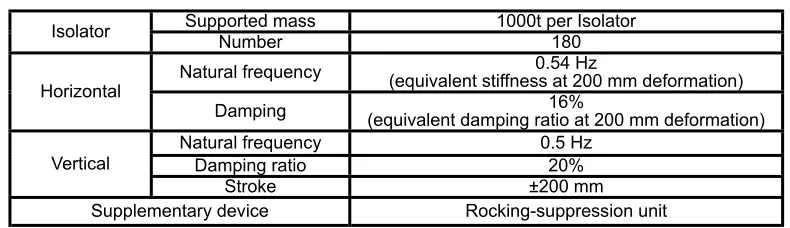
The basic specifications of the system adapted to the commercialized FBR mentioned earlier are as given in Table 1. For the commercialized FBR[3], a natural frequency below 1.0 Hz and a damping ratio above 20% in vertical direction has been specified, in keeping which, 0.5 Hz natural frequency and 20% damping ratio have been adopted as target of the pro-posed system.
The 180 isolators, each of 1000-ton loading capacity, are adapted to support the FBR structure of about 180,000 tons. Taking account of the sealing performance of the hydraulic fluid, each load-carrying cylinder of the isolator is dimensioned to let the fluid come to a pressure of 15 MPa when supporting a mass of 1,000 tons (not to exceed 25 MPa under added load due to seismic excitation).
The natural frequency and damping ratio in the horizontal direction have been derived without change from the dynamic characteristics of an existing 1,000-ton class high damping laminated rubber bearing, adopted for reference.
In the vertical direction, on the other hand, the natural frequency and damping ratio have been determined from the ac-cumulator unit specification. Envisaging the natural frequency of 0.5 Hz and damping ratio of 20% mentioned earlier, the calculation described in the following section has indicated that the first-stage accumulator with bladder should comprise four tanks of 120 liters each, filled with nitrogen gas at 15 MPa to 70% of the tank volume. From similar calculation, the
second-stage constant-volume accumulator has been made to comprise four tanks of 180-liter capacity each, individually connected to one of the first-stage tanks.
VERIFICATION TEST
Purpose of Test
With the intention of verifying the feasibility of the proposed system, a test was conducted covering the following items:
a. Natural frequency and damping ratio
To ascertain the feasibility of realizing the envisaged conditions of 0.5 Hz natural frequency and 20% damping ratio. b. Friction between piston and cylinder of load-carrying cylinder
To verify the efficacy of the bearings adopted for diminishing friction, which could affect system performance.
Method of Test
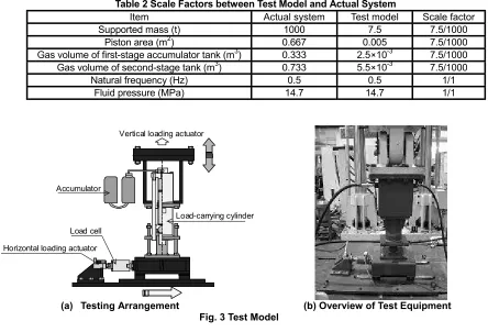
The scale factor to hold between the model adopted for the test and the system to be adopted in actual practice is indi-cated in Table 2. A ratio of 7.5:1000 has been adopted for the supported mass, for the piston area and for the volume of gas space in the first- and second-stage accumulator tanks. A scale factor of unity has been set for the hydraulic fluid pressure and for the pressure on the bearing subjected to horizontal seismic force (Fig. 1(a)), which respectively affect sealing per-formance and friction characteristics. The above scheme proved to equalize the calculated natural frequency between the systems of model and actual practice.
The testing arrangement is depicted in Fig. 3(a), and the equipment is illustrated in Fig. 3(b). An actuator is set to impart load to the upper part of the model for forcing its dynamic displacement. The flow-resisting orifice takes the form of a nee-dle valve, whose opening is varied by turns of the valve spinnee-dle, to examine the effect on system functioning that is brought by changes in orifice opening.
For piston friction testing, the model load-carrying cylinder is statically loaded horizontally to an intensity correspond-ing to seismic force.
Table 1 Main Isolation Specification for Commercialized FBR
Supported mass 1000t per Isolator
Isolator Number 180
Natural frequency (equivalent stiffness at 200 mm deformation)0.54 Hz Horizontal
Damping (equivalent damping ratio at 200 mm deformation)16%
Natural frequency 0.5 Hz
Damping ratio 20%
Vertical
Stroke ±200 mm
Table 2 Scale Factors between Test Model and Actual System
Item Actual system Test model Scale factor
Supported mass (t) 1000 7.5 7.5/1000
Piston area (m2) 0.667 0.005 7.5/1000
Gas volume of first-stage accumulator tank (m3) 0.333 2.5×10⁻³ 7.5/1000 Gas volume of second-stage tank (m3) 0.733 5.5×10⁻³ 7.5/1000
Natural frequency (Hz) 0.5 0.5 1/1
Fluid pressure (MPa) 14.7 14.7 1/1
Accumulator
Load-carrying cylinder Load cell
Horizontal loading actuator
Vertical loading actuator
(a) Testing Arrangement (b) Overview of Test Equipment
Fig. 3 Test Model
TEST RESULTS
Theory of orifice damping
The natural frequency of the system in the vertical direction is determined by the formula
2 1
2
1
V
V
A
g
f
+
=
γ
π
(1)where γ : Polytropic index
A : Piston surface area
V1 : Volume of gas space in first-stage tank
V2 : Volume of gas space in second-stage tank
The above relation is conditioned on the provision of an orifice with a sufficiently large opening located between the first- and second-stage accumulator tanks. As explained further on, the natural frequency is affected by the orifice opening. The natural frequency and damping ratio are evaluated applying Kunieda's “theory of orifice damping effect by air spring”[4]. This theory permits deriving through linearization
the energy dissipation brought by the pressure difference be-tween the two sides of an orifice, assuming the energy dissi-pation to be proportional to the square of gas velocity at the orifice.
Figure 4 presents resonance curves obtained using the above theory, indicating—for different orifice openings—the relation between amplification factor and excitation frequency.
0 2 4 6 8 10
0 0.5 1 1.5
A
m
p
lif
ic
atio
n
fa
ct
o
r
(X
/X0
)
15 mm 4 mm 2.5 mm 2 mm 1 mm orifice diameter
0 2 4 6 8 10
0 0.5 1 1.5
A
m
p
lif
ic
atio
n
fa
ct
o
r
(X
/X0
)
5
In Fig. 4 X0 and X are respectively excited ground displacement and absolute response displacement.
It can be seen that, with a very large orifice opening, when little orifice resistance is presented, the two accumulator tanks would function as a single vessel, to produce theoretical infinite resonance at a low frequency (natural frequency calculated from Eq. (1)). In the converse case of very small orifice opening, only the first-stage tank would effectively func-tion, to bring about infinite resonance at a high frequency.
With an intermediate orifice opening, the orifice resistance will lower the resonance to a finite level at an intermediate frequency, with curves for different orifice openings all passing through a fixed point. The orifice opening that brings the resonance frequency to this point is that which would minimize the amplification factor—i.e. which would maximize damping—and which would thus present the optimum orifice opening (2.5 mm orifice diameter in Fig. 4).
It must be noted, however, that different excitation amplitudes would produce different resonance frequencies and ampli-fication factors, i.e. that damping ratio and resonance frequency present nonlinear characteristics with change in orifice opening and excitation amplitude.
In the instance of the model used in the verification test, different orifice openings gave the performances presented in
Table 3. The damping ratio ζ under the optimum orifice condition is approximately expressed by the formula
+ =
2 1 2 1 2
1
V V
ζ
(2)
indicating that increasing the volume of the second-stage tank relative to that of the first stage will enhance damping. Making effective use of the above nonlinear relationship should permit devising measures for obtaining high resonance frequency with high damping effect, and for avoiding excessive piston stroke in the event of inordinately large seismic excitation.
Table 3 Resonance Frequency and Damping Ratio based on Orifice Damping Theory
Orifice opening Resonance frequency (Hz) Damping ratio (%)
Fully opened 0.52 0
Shut 0.94 0
Optimum opening 0.65 25
Natural frequency, damping coefficient
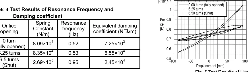
As an example of test result, Fig. 5 presents the hysteresis curves relating force to displacement for a typical case of 90 mm forced displacement at 0.06 Hz. The force is equal to [pressure × piston area] of the load-carrying cylinder. From the inclinations and surface areas of the three hysteresis curves, the stiffness and damping capacity have been derived as given in Table 4. In respect of stiffness, it is seen to increase with diminishing orifice opening, which behavior agrees with the theoretical data of Table 3.
Table 4 Test Results of Resonance Frequency and
Damping coefficient
Orifice opening
Spring Constant
(N/m)
Resonance frequency
(Hz)
Equivalent damping coefficient (N s/m)
0 turn
(Fully opened) 8.09×10⁴ 0.52 7.25×10³ 6.25 turns 8.35×10⁴ 0.53 6.55×10⁴
6.5 turns
(Shut) 2.69×10⁵ 0.95 2.45×10⁴
Fig. 5 Test Results of Hysteresis Curves In respect of damping, comparison between theoretical and empirical data calls for evaluating the relation between flow velocity and the pressure difference generated by the orifice and for quantitatively expressing the differences in loading
con-dition. As regards the first above requirement, the evaluation was made using the Cv value of needle valve, which is
ex-pressed by
V P CV
∆
= ρ (3)
where ρ : Specific gravity of gas
∆P : Pressure difference generated by orifice
V : Flow velocity
-100 -50 0 50 100
0.5 0.6 0.7 0.8 0.9 1 1.1 [×105]
Displacement [mm] For
ce [N]
0.00 turns (fully opened) 6.25 turns
The above equation indicates that the pressure difference ∆P is proportional to the square of flow velocity. The relation
between valve opening and Cv in the case of the orifice used in test was as shown in Fig. 6.
As regards the second requirement concerning differences in loading condition, this was evaluated by inversely deriving the flow velocity at orifice from the displacement forced on load-carrying cylinder.
The resulting comparison between theoretical and empirical data for equivalent damping coefficient is presented in Fig. 7. Good agreement between theory and test is seen for the orifice openings at 6.25 and 5.5 turns of spindle. With the orifice fully opened, the test data exceed the theoretical value, which can be ascribed to the resistance generated by the connecting piping two tanks, not considered in the theoretical calculation.
It can be concluded from the foregoing findings that, all in all, the system ensures good agreement with theory on values
of natural frequency and damping coefficient.
Friction characteristics
Test data obtained on friction characteristics are as presented in Fig. 8, which indicates the values of force registered on load cell mounted on actuator and those derived from the load-carrying cylinder fluid pressure. Friction resistance is the difference in force values between that from actuator load cell—which includes friction force—and that from cylinder fluid pressure—which it does not include.
Even in the absence of applied horizontal force, friction would be generated from such factors as sealing action. Actu-ally, however, the friction resistance proved to be only 4.4 kN at 29.4 kN horizontal force, corresponding to a friction coef-ficient of 0.15, which can be considered quite small.
The above performance can be attributed to the swivel mechanism provided on the load-carrying cylinder (see Fig. 1(a)), that avoids causing reaction on the upper bearing with the moment that would be generated when the load-carrying cylinder is subjected to horizontal seismic force.
1 2 3 4 5 6 7
0.1 0.2 0.3 0.4 0.5 0.6 0.7 0.8
0
Number of valve spindle turns Close ¨
© Open
Cv
0.02 0.04 0.06 0.08 0.1 20000
40000 60000 80000
0
Excited displacement [mm]
Equivalent viscous damping coefficient
[Ns/m]
0.0 turns (fully opend) 5.5 turns
6.25 turns Theory Experiment
Fig. 6 Characteristic Cv Value of the Valve Fig. 7 Comparison Between Theoretical and
7
SIMULATION OF ISOLATION PERFORMANCEModeling of Isolation System
For modeling the function of isolation system in horizontal, vertical and rotational directions, the characteristics of the system are represented by a spring and a damping element concentrated at the center of the actual isolation system. The horizontal spring element is represented by a modified bilinear model derived from a 1000-ton class high-damping laminated rubber bearing.
Envisaging an accumulator unit such as shown in Fig. 1(b), with the orifice generating a damping ratio of 20%, modeling of the vertical spring and damping element is obtained by com-bining a spring element with a damping element proportional to the square of flow velocity.
Modeling of the rotating element is obtained by means of the spring function provided by the hydraulic fluid column contained in the connecting piping between the load-carrying cylinder and the rocking-suppression cylinder. The bulk modulus of hydraulic fluid is assumed to be somewhat smaller than that of the hydraulic fluid in natural condition, in consid-eration of air immixture into the system, and elasticity of seal-ing material. This has led to a value of 4.3 Hz for the rockseal-ing mode natural frequency.
Consideration is also given to the friction of the piston in the load-carrying cylinder, and the effect is examined analyti-cally.
As input seismic waves for analysis, the S2 waves from a case study were used, which were estimated for application to the envisaged commercialized FBR.
Results of Horizontal and Rocking Response Analyses
Figure 9 presents the analyzed data of response to excited horizontal ground acceleration (diagram (a)), resulting in the horizontal response acceleration shown in diagram (b), the horizontal relative displacement of diagram (c), and the vertical displacement due to rocking motion of structure of diagram (d).
It is seen that, against a maximum ground acceleration of 831 gal, the response acceleration is 0.42 times. Relative dis-placement is 400 mm maximum, corresponding to about 250% in laminated rubber deformation, which is amply small.
Rocking of the structure (evaluated on the vertical dis-placement of structural edge) is suppressed to about 2 mm maximum, indicating markedly good rocking suppression performance.
Results of Vertical Response Analyses
Figure 10 shows frequency response curves for relative dis-placement, evaluated from the vertical response of an actual system, estimated by applying the theory of gas orifice damp-ing[4].
Comparing in Fig. 10 the results of analysis with linear model assuming 20% viscous damping, it is revealed that, for small amplitude, orifice damping yields a larger relative dis-placement response compared with viscous damping, but that increasing the input amplitude diminishes the response of ori
0 10 20 30 40 50 60 70
-1000 -500 0 500 1000
Time [s]
Acceleration [gal]
(a) Horizontal Ground Acceleration
0 10 20 30 40 50 60 70
-500 0 500
-348.1
Time [s]
Acceleration [gal]
219.1
(b) Horizontal Response Acceleration
0 10 20 30 40 50 60 70
-500 0 500
Time [s]
Displacement [mm]
-385.12 397.6
(c)Horizontal Relative Displacement
0 10 20 30 40 50 60 70
-3 -2 -10 1 2 3
Time [s]
Displacement [mm]
-2.123 1.427
(d) Vertical Displacement due to Rocking Motion
Fig. 9 Analyzed Data of Horizontal and Rocking Responses
0.1 0.5 1 5 10
0.1 0.5 1 5 10
CV = 107.5
Frequency [Hz]
Amplification factor (X-X
0
)/X)
X0 = 50 [mm]
X0 = 100 [mm]
X0 = 150 [mm]
Viscous damping (0.5 [Hz], 20%)
fice damping below that of viscous damping, and raises the resonance frequency.
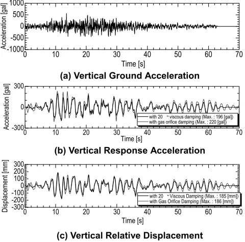
Using the same model, the response of an actual system to seismic acceleration was analyzed, the results being as shown in Fig. 11. This figure presents the analyzed data of response to excited vertical ground acceleration (diagram (a)), resulting in the vertical response acceleration shown in diagram (b), and the vertical relative displacement of diagram (c).
As it was in Fig. 10, the above results again indicate re-sponse characteristics similar to those obtained from analysis with the 20% viscous damping model. It can thus be concluded that orifice damping is roughly equivalent to 20% viscous damping.
Shown in Fig. 12 are the same response waves as in Fig. 11, but with account taken of the friction characteristics of the load-carrying cylinder obtained from test. In the analysis, the relation between horizontal force and friction force was adapted for applying the test results to the actual system, and the resulting relation was applied to the horizontal force de-rived from horizontal response analysis. It can be concluded that a friction force of level such as applied in test should, if anything, rather contribute to diminishing structural displace-ment.
CONCLUSIONS
Model tests have been performed to verify the expected per-formance of a three-dimensional seismic base isolation system, as proposed by the authors, incorporating hydraulic mechanism to ensure adequate vertical isolation. The tests have proved good agreement of performance between theoretical calculation and test data in respect of natural frequency and damping ratio, thus confirming the feasibility of realizing the envisaged conditions of 0.5 Hz natural frequency and 20% damping ratio.
From the response analysis reflecting the test results, it was indicated that, upon practical application on the envisaged commercialized FBR, the system should reduce vertical accele-ration by around 2/3. Marked suppression of structural rocking motion was also indicated, that would limit vertical displace-ment due to rocking motion to about 2 mm under seismic exci-tation. The proposed system is concluded to be well applicable to the envisaged commercialized FBR.
ACKNOWLEDGMENT
The present study has been undertaken in pursuance of a research and development project on three-dimensional seismic isolation sponsored by the Government of Japan. The authors take this occasion to express their profound appreciation of the unreserved encouragement and support accorded to them in their work by the Project Committee members.
REFERENCES
1. Fujita, T., 1996, ”Technology for Earthquake-Resistant Structures in the Twenty-First Century,” Journal of the Japan Society of Mechanical Engineers, Vol.99, No.935, pp.59-64, in Japanese.
2. Kashiwazaki, A., Mita R., Enomoto, T. and Akimoto, M., “Three-Dimensional Base Isolation System Equipped with Hydraulic Mechanism”, 1999, Transactions of the Japan Society of Mechanical Engineers, Vol.66, No.648, pp.146-151, in Japanese.
3. Kato, A., Umeki, K., Morishita, M., Fujita, T. and Midorikawa, S., “A Large Scale Ongoing R&D Project on Three-Dimensional Seismic Isolation for FBR in Japan”, Aug. 2002, ASME PVP.
4. Kunieda, M., 1999, “Orifice Damping Effect by Air Spring”, Vibration Isolation Rubber (New Edition), Japan Association of Rolling Stock Industries, pp.192-194, in Japanese.
0 10 20 30 40 50 60 70
-1000 -500 0 500 1000
Time [s]
Acceleration [gal]
(a) Vertical Ground Acceleration
0 10 20 30 40 50 60 70
-300 0 300
with 20 “ viscous damping (Max. : 196 [gal]) with gas orifice damping (Max. : 220 [gal])
Time [s]
Acceleration [gal]
(b) Vertical Response Acceleration
0 10 20 30 40 50 60 70
-300 -200 -1000 100 200 300
Time [s]
Displacement [mm]
with 20“ Viscous Damping (Max. : 185 [mm])
with Gas Orifice Damping (Max. : 186 [mm])
(c) Vertical Relative Displacement
Fig. 11 Analyzed Data of Vertical Response
0 10 20 30 40 50 60 70
-300 0 300
with friction iMax. = 194.6 [gal] j
without friction iMax. = 196.0 [gal] j
Ti [ ]
Acceleration [gal]
(a) Vertical Response Acceleration
0 10 20 30 40 50 60 70
-300 -200 -1000 100 200 300
Time [s]
Displacement [mm]
with Friction (Max. : 138 [mm]) without Friction (Max. : 185 [mm])
(b) Vertical Response displacement