Volume 2009, Article ID 893751,10pages doi:10.1155/2009/893751
Research Article
An Adaptive Channel Interpolator Based on Kalman Filter for
LTE Uplink in High Doppler Spread Environments
Bahattin Karakaya,
1H¨
useyin Arslan,
2and Hakan A. C¸ırpan
11Department of Electrical and Electronics Engineering, Istanbul University, Avcilar, 34320 Istanbul, Turkey
2Department of Electrical Engineering, University of South Florida, 4202 E. Fowler Avenue, ENB118, Tampa, FL 33620, USA
Correspondence should be addressed to Bahattin Karakaya,[email protected]
Received 17 February 2009; Revised 5 June 2009; Accepted 27 July 2009
Recommended by Cornelius van Rensburg
Long-Term Evolution (LTE) systems will employ single carrier frequency division multiple access (SC-FDMA) for the uplink. Similar to the Orthogonal frequency-division multiple access (OFDMA) technology, SC-FDMA is sensitive to frequency offsets leading to intercarrier interference (ICI). In this paper, we propose a Kalman filter-based approach in order to mitigate ICI under high Doppler spread scenarios by tracking the variation of channel taps jointly in time domain for LTE uplink systems. Upon acquiring the estimates of channel taps from the Kalman tracker, we employ an interpolation algorithm based on polynomial fitting whose order is changed adaptively. The proposed method is evaluated under four different scenarios with different settings in order to reflect the impact of various critical parameters on the performance such as propagation environment, speed, and size of resource block (RB) assignments. Results are given along with discussions.
Copyright © 2009 Bahattin Karakaya et al. This is an open access article distributed under the Creative Commons Attribution License, which permits unrestricted use, distribution, and reproduction in any medium, provided the original work is properly cited.
1. Introduction
3GPP Long-Term Evolution (LTE) aims at improving the Universal Mobile Telecommunication System (UMTS) mo-bile phone standard to cope with future requirements. The LTE project is not a standard itself, but it will result in the new evolved Release 8 of the UMTS standard, including most or all of the extensions and modifications of the UMTS system. Orthogonal frequency-division multiplexing (OFDM) is considered as the strongest candidate of the technology that will be deployed in LTE because of its advantages in lessening the severe effect of frequency selective fading. Since wide-band channels experience frequency selectivity because of multipath effect single-carrier modulations necessitate the use of equalizers whose implementations are impractical due to their complexities. Therefore, OFDM is selected in order to overcome these drawbacks of single-carrier modulation techniques [1]. In OFDM, the entire signal bandwidth is divided into a number of narrower bands or orthogonal subcarriers, and signal is transmitted over those bands in parallel. This way, computationally complex intersymbol
interference (ISI) equalization is avoided and channel esti-mation/equalization task becomes easier. However, orthog-onal frequency-division multiple accessing (OFDMA) has a high peak-to-average power ratio (PAPR) because of very pronounced envelope fluctuations, which will decrease the power efficiency in user equipment (UE) and thus decrease the coverage efficiency in uplink for the low cost power amplifier (PA). Moreover, in the uplink, inevitable frequency offset error caused by different terminals that transmit simultaneously destroys the orthogonality of the transmissions leading to multiple access interference [2].
OFDMA, where time domain data symbols are transformed into frequency-domain by a DFT before going through OFDMA modulation [2]. Therefore, air interface of Release 8 is being referred to as Evolved Universal Terrestrial Radio Access (E-UTRA) which is assumed to employ SC-FDMA for the uplink and OFDMA for the downlink [3].
To the best knowledge of authors, the very first papers addressing the channel estimation problem in the context of SC-FDMA are [4,5] both of which consider time-invariant frequency-selective multipath channels, throughout an SC-FDMA symbol. In these papers, zeroforcing (ZF) or mini-mum mean squared error (MMSE) linear channel estimation methods have been proposed in frequency-domain although they all suffer from ICI, without proposing any cancellation method. Note that, since most of the next generation wire-less network standards require transmission in high speed environments, time-variant frequency-selective multipath assumption should be considered rather than time-invariant frequency-selective multipath assumption. However, it is important to note that when the channel is time-variant, the subcarrier orthogonality is destroyed giving rise to ICI due to channel variation within an SC-FDMA symbol.
Even though they are not in SC-FDMA context, there are methods proposed in the literature dealing with ICI mitigation for OFDM-based systems [6–8]. In [6], receiver antenna diversity has been proposed; however, high normal-ized Doppler spread reduces the efficiency of this approach. In [7], a piece-wise linear approximation is proposed based on a comb-type pilot subcarrier allocation scheme in order to track the time-variations of the channel. In [8] Modified Kalman filter- (MKF-) based time-domain channel estimation approach for OFDM with fast fading channels has been investigated. The proposed receiver structure models the time-varying channel as an AR-process; tracks the channel with MKF; performs curve fitting, extrapolation and MMSE time domain equalizer. In [9], matched filter, LS and MMSE estimator that incorporate decision feedback low complexity time-domain channel estimation and detection techniques are presented for multicarrier signals in a fast and frequency-selective Rayleigh fading channel for OFDM systems. Moreover, polynomial interpolation approaches have been commonly used for channel estimation [10].
In this paper, we focus on a major challenge, namely, the SC-FDMA transmission over time-varying multipath fading channels in very high speed environments, which is regarded as one of the most difficult problems in 3GPP systems. Inspired by the conclusions in [6–9], the signal model in [9] is extended to SC-FDMA systems. A channel estimation algorithm based on Kalman filter and a polynomial curve fitting interpolator whose order is selected adaptively is proposed for LTE uplink systems which include time-varying channels in high speed environments. The variations of channel taps are tracked jointly by Kalman filter in time domain during training symbols. Since channel tap information is missing between the training symbols of two consecutive slots within a single subframe, an interpolation operation is performed to recover it. Hence, the interpolation is established by using a polynomial curve fitting that is based on linear model estimator. The contributions of this
study are twofold. (i) The factors which affect the selection of the order of the polynomial curve fitting interpolator are identified; (ii) A procedure that is based on mean squared error (MSE) is developed in order to determine the optimum polynomial order values.
The remainder of the paper is organized as follows. Section 2outlines the characteristics of the channel model considered along with a discussion that is related to sample-spaced and fractional-sample-spaced channel impulse response con-cerns. InSection 3, LTE uplink system model is introduced and subcarrier mapping is discussed. In addition, the impact of ICI is formally described for SC-FDMA system.Section 4 provides the details of frequency-domain least squares chan-nel estimation, Kalman filter tracking, and polynomial curve fitting interpolation along with the discussion regarding the selection of its order.Section 5introduces simulation setups for various scenarios and presents corresponding perfor-mance results. Finally, inSection 6, concluding remarks are given along with possible future research directions.
2. Channel Model
The complex baseband representation of a wireless mobile time-variant channel impulse response (CIR) can be de-scribed by
h(t,τ)= i
αi(t)δ(t−τi), (1)
where αi(t) is the time-variant complex tap coefficients
of the ith path, and τi is the corresponding path delay.
The fading channel coefficients αi(t) are modeled as zero
mean complex Gaussian random variables. Based on the Wide Sense Stationary Uncorrelated Scattering (WSSUS) assumption, the fading channel coefficients in different delay taps are statistically independent. In time domain, fading coefficients are correlated and have Doppler power spectrum density modeled as in [11] with the following autocorrelation function:
2}denotes the average power of the
ith path channel coefficient,fdis the maximum Doppler
fre-quency in Hertz, and (·)∗represents the complex conjugate operation. The term fdTsrepresents the normalized Doppler
frequency;Tsis the sampling period.J0(·) is the zeroth-order
Bessel function of the first kind.
Considering the effect of transmitter-receiver pair in a more generalized way, (1) can be written as follows [12]:
h(t,τ)=h(t,τ)∗c(τ)= i
αi(t)c(t−τi), (3)
which corresponds to the Nyquist filter. Continuous channel transfer function (CTF) can be obtained from (3) as follows:
Ht,f=
where C(f) is the Fourier transform of impulse response, c(τ), of the transceiver pair. For LTE Uplink system of interest, which uses a sufficiently long cyclic prefix (CP) and adequate synchronization, the discrete subcarrier-related CTF can be expressed as
H[m,n]HmTs,nΔf
is the CIR which has sample-spaced delays atlTstime instant. Mdenotes the number of SC-FDMA subcarriers,Tsdenotes
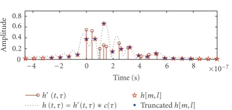
the base-band signal’s sample duration, L and L denote the number of fractionally-spaced channel paths and the number of equivalent sample spaced CIR taps, respectively. Note that because of the convolution with impulse response of the system, sample-spaced CIR (SS-CIR) has correlated nonzero taps compared to fractionally spaced CIR (FS-CIR). Due to the band limited property of the physical systems, SS-CIR cannot be implemented with limited number of components. One of the solutions to this problem is to truncate SS-CIR in such a way that most of its energy is preserved in the truncated part. In this study, truncation strategy is adopted in simulations. However, for the sake of completeness, inFigure 1, the impact of truncation strategy is illustrated for 3GPP rural area channel model for a bandwidth of 10 MHz. All of the steps prior to truncation operation, which are given in (1), (3), and (6), respectively, are given in this figure with appropriate labels.
3. System Model
Figure 2 shows the discrete baseband equivalent system model. We assume anN-point DFT for spreading the pth users time domain signald[k] into frequency-domain:
D(p)[κ]=
Figure 1: 3GPP rural area channel model for a bandwidth of
10 MHz. Note that all of the steps prior to truncation operation are illusturated with appropriate labels corresponding to (1), (3), and (6), respectively.
After spreading,D(p)[κ] is mapped onto thenth subcarrier M > N. The fundamental unit of spectrum for LTE uplink is a single subcarrier. A Resource block (RB) is composed of 12 adjacent subcarriers and forms the fundamental unit of resources to be assigned a single user as illustrated in Figure 3. Assigning adjacent RBs to a single user is called localized mapping which is the current working assumption in LTE [13]. Alternatively, if RBs are assigned apart, then, it is called distributed mapping, which is generally employed for frequency diversity [3] and possible candidate for LTE Advanced.
The transmitted single carrier signal at sample timemis given by
The received signal at base station can be expressed as
y[m]= number of paths of the frequency selective fading channel, andw[m] is the additive white Gaussian noise (AWGN) with
N(0,σ2 w).
In this paper, we assume that there is only one user,P = 1, therefore (10) becomes
y[m]= L−1
l=0
Data processing Data processing
Pilot processing
Pilot processing DFT
Figure2: SC-FDMA transceiver system model.
Channel bandwidth [5 MHz−M=512 IFFT size]
Transmission bandwidth [9 RB−N=108 DFT size]
Transmission bandwidth configuration [25 RB=25×12 subcarriers]
Guard band
Figure3: An example subcarrier mapping for a specific scenario.
By plugging (9) into (11), the received signal can be rewritten as follows:
When (5) is placed into (12), it yields:
y[m]= 1 M
M−1
n=0
S[n]H[m,n]ej2πmn/M+w[m]. (13)
Thus FFT output atnth subcarrier can be expressed in the following form:
whereH[n] represents frequency-domain channel response expressed as
and I[n] is ICI caused by the time-varying nature of the channel given as
andW[n] represents Fourier transform of noise vectorw[m] as follows:
W[n]= M−1
m=0
w[m]e−j2πmn/M. (17)
during the data symbols between two consecutive pilots is obtained by interpolation.
We assume that equalization is performed in frequency-domain after the subcarrier demapping block. Data are obtained after the demapping described as
X[κ]=Y[n], wheren∈ΓN[κ]
=D[κ]H[n] +I[n] +W[n]. (18)
4. Channel Estimation
4.1. Frequency-Domain Least Squares Estimation. In this study, frequency-domain least squares channel estimation is employed in order to find the initial values required by Kalman filter. Channel frequency response, which corre-sponds to used subcarriers, can be found by the following equation:
sequence known by the receiver. If (5) and (15) are considered together, yielding time average of time-varying frequency response over one SC-FDMA symbol is
H[n]=
where h[l] is the time average of time-varying impulse response over one SC-FDMA symbol:
h[l]= 1 M
M−1
m=0
h[m,l]. (21)
It can be easily observed that in (22) and (20) the DFT pair will result in corresponding channel representations both in time and frequency-domains, respectively,
h[l]= M−1
n=0
H[n]e−j2πnl/M. (22)
Hence, in order to initial values for Kalman filtering in time domain, we can writeM-point IFFT ofH0[n] as
Recall that in (19) some of the subcarriers are left unused for a given user. It is also known that transform-domain techniques introduce CIR path leaks due to the suppression of unused subcarriers [14]. Besides, Kalman filter needs time-domain samples in order to initiate the tracking procedure. However, due to the aforementioned
leakage problem, unused subcarriers for a given user will create inaccurate time-domain value. In the literature, the problem has been studied for a single user OFDM system in [15–17]. As mentioned before, leakage problem just affects the initialization of the algorithm therefore we do not focus on the leakage problem and in the subsequent subsection Kalman filtering is introduced along with this inherent leakage problem. By using sophisticated solutions for the leakage problem, initialization of the Kalman can also be improved.
4.2. Kalman Filtering. It was shown that time selective fading channel can be sufficiently approximated by using first-order autoregressive (AR) model. Time-varying channel taps can be modeled through the use of a first-order AR process in the vector form as follows [18,19]:
h[m+ 1]=βh[m] +v[m+ 1], (24)
whereh[m]=[h[m, 0],. . .,h[m,L−1]], which is also called process equation in Kalman filtering [20].v[m] andβILare
called process noise and state transition matrix, respectively. The correlation matrix of the process noise and the state transition matrix can be obtained through the Yule-Walker equation [21]
delay profile of the channel. The equivalent of (11), which is a measurement equation in the state-space model of Kalman filter, can be shown in vector form as
y[m]=sT[m]h[m] +w[m], (26) updating rule of recursion is as follows:
h[m+ 1]=βh[m] +K[m]e[m],
P[m+ 1]=ββI−K[m]sT[m]P[m] +Q[m+ 1]. (28)
A frame
1. slot 2. slot · · · i. slot j. slot · · · 19. slot 20. slot
1. symb
2.
symb · · ·
η.
symb
Cyclic prefix Data
A subframe
Reference signal (training symbol)
Figure4: An LTE uplink type 1 frame structure with extended CP. In one slot there are six symbols for extended CP case whereas there are
seven symbols for normal CP case [3].
i. slot j. slot
Real tap values KF estimates Interpolater estimates
Cyclic prefix Data
Reference signal (training symbol)
mi,M
mi,1 mj,1 mj,M Time
Figure5: Kalman tracking and polynomial curve fitting procedure applied in consecutive slots with type 1 frame structure and extended CP
size.
linear model estimator. Note that, in this study, it is assumed that within one training symbol duration the channel is time-variant. Kalman filter is employed in order to keep track of the changes within a single training symbol; therefore, these estimates are mandatory for interpolating the values in between because the channel might vary significantly from one training symbol to the next one. Curve fitting is established by estimating the coefficients of the polynomial of interest. In order to estimate the coefficients, in this study, the linear model estimator is applied to the channel tap estimates generated by Kalman tracker within training symbols; seeFigure 5. The linear model considered here can be expressed in the following form [22]:
Ξ[l]=Σ·Θ[l], (29)
whereΞ[l]=[h[mi,1,l],. . .,h[mi,M,l],h[mj,1,l],. . .,h[mj,M, l]T is a 2M×1 vector of observations supplied bylth path Kalman filter channel estimates, and mi,a and mj,aa =
1,. . .,Mare time instants of training symbols.Σ=[VTiVTj]T
is a known 2M×νmatrix which is constructed with two Van-dermonde matricesVi(k,μ) = m
μ−1
i,k ,Vj(k,μ) = m μ−1 j,k ,k =
1,. . .,Mandμ=1,. . .,ν.Θ[l]=[θ1[l],. . .,θν[l]]Tis aν×1
vector of polynomial coefficients to be estimated andνis the order of the polynomial. In order to obtain the estimates, classical least-squares approach is employed as follows:
Θ[l]=ΣTΣ−1ΣTΞ[l]. (30)
Based on the general description of the linear model and its estimator given in (29) and (30), respectively, the channel taps that are estimated with the aid of interpolation operation are given by
h[m,l]=ν μ=1
θμ[l]mμ−1, mi,M< m < mj,1. (31)
250 350 450 500
M
o
b
ile
speed
(km/h)
27 30 33 36 42 57 72
Third-order region
First-order region
Second-order region
SNR (dB)
Figure6: An example of polynomial curve fitting order selection
chart based on SNR-mobile speed pair. This chart is calculated through the use of numerical methods for 3 MHz of bandwidth with fully assigned RBs to a single user in a rural area.
Selection of the order of the polynomial depends on many factors such as distance between training symbols in time, maximum Doppler shift, SNR, propagation environment including number of multipath components and delay spread, and so on. In other words, all of the parameters that affect the performance of the tracker and some of the structural factors (e.g., training symbol placements) have an influence on the order of the polynomial. In this study, to decide on the order of the polynomial, mean squared error (MSE) is selected to be the performance metric in the following manner:
MSE= 1 L
l
1 M
m
h[m,l]−h[m,l]2. (32)
Because the proposed method requires the order of the polynomial as an input, a special scenario in which Doppler, SNR, and propagation environment are taken into account while neglecting the impact of the rest of the aforementioned factors is investigated. The order information is obtained via steps (29) through (32) in a recursive fashion and recursion is terminated when the MSE reaches its minimum for a specific case. Figure 6 plots an instance of the output of this procedure which solely focuses on mobile speed-SNR pair. It is seen in this figure that low SNR values actually prevent the selection of higher orders due to the deteriorated tracker performance. However in realistic scenarios, channel parameters are not known exactly, prior knowledge on channel and its statistics can be used to form look-up table which contains optimum order values for various scenarios.
We now summarize the proposed method for LTE uplink systems.
Step 1. Initialization. Frequency-domain LS estimation to obtain initial tracking parameters for Kalman filter.
Step 2. Tracking. Jointly track CIR taps with Kalman filter employing training sybols.
Table1: 3GPP channel models which are used in simulations.
Channel model FS-CIR 1.4 MHz 3 MHz 5 MHz SS-CIR SS-CIR SS-CIR
TUx 20 13 17 25
RAx 10 10 11 13
Table2: LTE uplink simulation parameters.
Parameters 1.4 MHz 3 MHz 5 MHz Sampling frequency, fs 1.92 MHz 3.84 MHz 7.68 MHz
FFT size,M 128 256 512
Maximum available
subcarriers,N 72 (6 RB) 180 (15 RB) 300 (25 RB)
Extended CP 32 64 128
Step 3. Order decision. Decide the order of the polynomial from the look-up table (i.e.,Figure 6).
Step 4. Coefficient Estimation. Compute the polynomial coefficients by applying least-squares approach (30) to the linear model (29) of Kalman estimates and Vandermonde matrix of corresponding time instants.
Step 5. Curve Fitting. Estimate the CIR taps from data symbols by using polynomial coefficients.
5. Simulation Results
In this section, computer simulation results are presented in order to evaluate the performance of the proposed channel estimation technique for LTE uplink systems. In simulations, the channel models given in [23] are used. Only typical urban (TUx) and rural area (RAx) models are taken into account. In addition to the default speed values, higher speed values are also considered in simulations. It is important to state one more time that there is a discrepancy between the number of channel taps given in [23] and simulated ones due to the reasons explained in Section 2. A comparison of these discrepancies with respect to different settings can be found inTable 1by using the FS-CIR and SS-CIR notions.
A QPSK modulation format is employed. We consider type 1 frame structure, constant amplitude zero autocor-relation (CAZAC) pilot sequences, and extended CP size for LTE uplink [13]. As shown in Figure 4, frames have 20 slots, and each slot has six symbols. Fourth symbol in each slot is a pilot symbol, and the rest is data symbols. Critical parameters of simulation environments are given inTable 2. In each simulation loop, one frame (100 data symbols) is transmitted. In what follows, simulation scenarios are presented sequentially in detail.
10−3
10−2
10−1
100
BER
0 5 10 15 20 25 30 35 40
M1−v=60 km/h M2−v=60 km/h M1−v=120 km/h
M2−v=120 km/h M3−v=60 km/h M3−v=120 km/h SNR (dB)
Figure7: BER performance comparisons of methods for scenario
1. M1: the proposed method which is LS estimate is obtained from the pilots for the CFR used with the Kalman filter and then linear interpolation is used for symbols in between. M2: frequency-domain LS is used. M3: perfect channel state information is used.
statistics. The results are plotted inFigure 7. The proposed method (Method 1—M1) is compared with two methods. In the first method, perfect CSI (Method 3—M3) is fed into the equalization process, whereas in the second one, which is outlined inSection 4.1, LS estimates (Method 2—M2) of CSI are used. It is worth mentioning that in the M2 the same channel frequency response (CFR) estimates are used until the next reference (training) symbol. As expected, M3 case provides the best performance among all. On the other hand, M2 performs the worst among all of the methods considered in this scenario, since it neither keeps track of the channel during data symbols nor takes the channel variation into account during the training sequence. Furthermore, during the training sequence, it just calculates the average CSI which is already contaminated by noise. Note that the performance of M1 is placed in between these two cases while its performance converges that of M3 case for low SNR values, whereas diverging it diverges for high SNR values. This is not surprising, because high SNR values allow one to observe the irreducible ICI error floor due to time-varying channel. Also note that for M3 case faster speed corresponds to better performance because when a proper detection technique is adopted, the time-varying nature of the channel can be exploited as a provider of time diversity [9].
Scenario 2. In this scenario, the impact of adaptive selection of the order of polynomial curve fitting on the performance of the method proposed is investigated with the following settings. Transmission bandwidth is 3 MHz, all resource blocks are assigned to one user, and the channel environment is rural area so there are 11 taps to track and the mobile
10−2
10−1
100
BER
0 10 20 30 40 50 60 70
M1−v=250 km/h M2−v=250 km/h M1−v=350 km/h
M2−v=350 km/h M1−v=450 km/h M2−v=450 km/h SNR (dB)
Figure8: BER performance comparisons of different methods with
respect to the method proposed which employs polynomial curve fitting whose orders are selected adaptively in senario 2 for different mobile speed values. Note that the performance of the method proposed exhibits a staircase-like behavior over the SNR values that correspond to the order shifts which can also be cross-checked with the points given inFigure 6. M1: the proposed method which is LS estimate is obtained from the pilots for the CFR used with the Kalman filter and then linear interpolation is used for symbols in between. M2: frequency-domain LS is used.
speeds are 250 Km/h, 350 Km/h, and 450 Km/h. The pro-posed method (M1) and LS estimates (M2) which is afore-mentioned in Scenario 1 are compared to each other with respect to their bit error rate (BER) performances inFigure 8. It is worth noting that the performance of the proposed method improves by experiencing a staircase-like effect. This stems from changing the order of the polynomial curve fitting adaptively based on the results presented inFigure 6. In addition to comparative analysis, the MSE performance of the method proposed is also investigated inFigure 9. In conjunction with BER performances, as can be seen in both Figures 8 and 9, drastic drops in the performance curves occur in parallel to the corresponding mobile speed-SNR pairs given in Figure 6. It is very important to state that, the results presented in Figure 6are peculiar to the setup considered here and calculated through the use of numerical methods, since its analysis is out of the scope of this study.
10−4
10−3
10−2
MSE
0 10 20 30 40 50 60 70
v=250 km/h v=350 km/h v=450 km/h
SNR (dB)
Figure 9: MSE performances of the method proposed which
employs polynomial curve fitting whose orders are selected adap-tively in Senario 2 for different mobile speed values. Note that the performance of the method proposed exhibits a staircase-like behavior over the SNR values that correspond to the order shifts which can also be cross-checked with the points given inFigure 6.
10−5
10−4
10−3
10−2
MSE
0 10 20 30 40 50 60 70
15 RB 14 RB 13 RB
SNR (dB)
Figure10: MSE performance comparisons for different resource
block assignments to a single user in Scenario 3. Note that a decrease in number of assigned resource block worsens the performance stemming from the leakage problem.
Kalman tracker. In order to see how this leakage problem influences the MSE performance of the method proposed, another simulation setup is constructed with the following parameters. Transmission bandwidth is 3 MHz; different numbers of RBs are assigned one user each time in a typical rural area environment in which there are 11 taps
10−4
10−3
10−2
10−1
MSE
0 10 20 30 40 50 60 70
Rural area Typical urban
SNR (dB)
Figure11: MSE performance comparisons for different
propaga-tion channel environments in Scenario 4.
to track for a fixed mobile speed of 120 Km/h. The results are given in Figure 10. In this figure, it is clearly observed that assigning less number of RBs gives rise to poorer performances compared to those of which are assigned more RBs. This stems from the fact that less number of RBs causes more leakage yielding worse accuracy in the initial values of channel taps in time domain.
Scenario 4. Finally, the overall impact of propagation en-vironment is also investigated through the simulations. Two different setups, namely, rural and typical urban area environments, are considered with the following common parameters. Transmission bandwidth is 3 MHz, all RBs are assigned to one user, and the mobile speed is 120 Km/h. The results are plotted in Figure 11. It is clear that the performance is significantly dropped in a typical urban area compared to that in rural area because the number of channel taps in a typical urban is greater than that in rural area, as specified in Table 1. Since Kalman filter strives to track the taps jointly in time, having a larger number of channel taps yields worse performance, as expected.
6. Concluding Remarks and Future Directions
of the polynomial adaptively improves the BER performance significantly. However, as in most of the OFDM-based sys-tems, the method proposed suffers from transform domain techniques as well, since they introduce CIR path leaks due to the suppression of unused subcarriers [14].
This study also reveals that selection of the order of the polynomial used in interpolation depends on many factors such as distance between training symbols in time, maximum Doppler shift, SNR, propagation environment including number of multipath components and delay spread, and so on. However, to the best knowledge of authors, there is no closed-form expression that takes all of the aforementioned factors into account and determines the optimum order value for the interpolation polynomial. In case deriving a closed-form expression is impossible or intractable, generating look-up tables which contain the optimum order values for various scenarios is essential.
The performance of the proposed approach directly related to Kalman filter performance. Specifically for more than one user case Kalman performance will be effected by initialization and the number of parameters to be tracked. Since unused subcarriers increase additional chan-nel impulse response path leakage will degrade the perfor-mance of the initialization resulting in overall perforperfor-mance degradation in the proposed approach.
Acknowledgments
The authors would like to thank WCSP group members at USF for their insightful comments and helpful discussions. The authors would like to acknowledge the use of the services provided by Research Computing, University of South Florida. This work is supported in part by the Turk-ish Scientific and Technical Research Institute (TUBITAK) under Grant no. 108E054 and Research Fund of the Istanbul University under Projects UDP-2042/23012008, T-880/02062006. Part of the results of this paper is presented at the IEEE-WCNC, USA, March 31-April 3, 2008.
References
[1] R. van Nee and R. Prasad, OFDM for Wireless Multimedia Communications, Artech House, Norwood, Mass, USA, 2000. [2] H. G. Myung, J. Lim, and D. J. Goodman, “Single carrier
FDMA for uplink wireless transmission,” IEEE Vehicular Technology Magazine, vol. 1, no. 3, pp. 30–38, 2006.
[3] 3GPP, TR 25.814, “Physical Layer Aspects for Evolved UTRA,”
http://www.3gpp.org/.
[4] D. Grieco, K. Pan, R. Olesen, and N. Shah, “Uplink single-user MIMO for 3GPP LTE,” in Proceedings of the 18th IEEE International Symposium on Personal, Indoor and Mobile Radio Communications (PIMRC ’07), pp. 1–5, Athens, Greece, September 2007.
[5] D.-H. Lee, S.-B. Im, and H.-J. Choi, “A novel pilot mapping method for channel-quality estimation in SC-FDMA system,” inProceedings of Asia-Pacific Conference on Communications (APCC ’07), pp. 307–310, 2007.
[6] M. Russell and G. L. Stuber, “Interchannel interference analysis of OFDM in a mobile environment,” inProceedings of the 45th IEEE Vehicular Technology Conference (VTC ’95), vol. 2, pp. 820–824, Chicago, Ill, USA, July 1995.
[7] Y. Mostofi and D. C. Cox, “ICI mitigation for pilot-aided OFDM mobile systems,”IEEE Transactions on Wireless Com-munications, vol. 4, no. 2, pp. 765–774, 2005.
[8] K.-Y. Han, S.-W. Lee, J.-S. Lim, and K.-M. Sung, “Channel estimation for OFDM with fast fading channels by modified Kalman filter,”IEEE Transactions on Consumer Electronics, vol. 50, no. 2, pp. 443–449, 2004.
[9] Y.-S. Choi, P. J. Voltz, and F. A. Cassara, “On channel estimation and detection for multicarrier signals in fast and selective Rayleigh fading channels,” IEEE Transactions on Communications, vol. 49, no. 8, pp. 1375–1387, 2001. [10] W. H. Chin, D. B. Ward, and A. G. Constantinides, “An
algorithm for exploiting channel time selectivity in pilot-aided MIMO systems,”IET Communications, vol. 1, no. 6, pp. 1267– 1273, 2007.
[11] W. Jakes and D. Cox, Microwave Mobile Communications, Wiley-IEEE Press, New York, NY, USA, 1994.
[12] J. Akhtman and L. Hanzo, “Sample-spaced and fractionally-spaced cir estimation aided decision directed channel estima-tion for OFDM and MC-CDMA,” inProceedings of the 62nd IEEE Vehicular Technology Conference (VTC ’05), vol. 3, pp. 1916–1920, Dallas, Tex, USA, September 2005.
[13] 3GPP, TS 36.211 V8.6.0, “Physical Channels and Modulation,”
http://www.3gpp.org/.
[14] M. Ozdemir and H. Arslan, “Channel estimation for wireless ofdm systems,”IEEE Communications Surveys & Tutorials, vol. 9, no. 2, pp. 18–48, 2007.
[15] K. Kwak, S. Lee, J. Kim, and D. Hong, “A new DFT-based channel estimation approach for OFDM with virtual sub-carriers by leakage estimation,”IEEE Transactions on Wireless Communications, vol. 7, no. 6, pp. 2004–2008, 2008.
[16] D. Li, F. Guo, G. Li, and L. Cai, “Enhanced DFT interpolation-based channel estimation for OFDM systems with virtual subcarriers,” inProceedings of the IEEE 63rd Vehicular Technol-ogy Conference (VTC ’06), vol. 4, pp. 1580–1584, Melbourne, Australia, May 2006.
[17] B. Yang, Z. Cao, and K. Letaief, “Analysis of low-complexity windowed DFT-based MMSE channel estimator for OFDM systems,”IEEE Transactions on Communications, vol. 49, no. 11, pp. 1977–1987, 2001.
[18] L. M. Davis, L. B. Collings, and R. J. Evans, “Coupled estimators for equalization of fast-fading mobile channels,”
IEEE Transactions on Communications, vol. 46, no. 10, pp. 1262–1265, 1998.
[19] M. K. Tsatsanis, G. B. Giannakis, and G. Zhou, “Estimation and equalization of fading channels with random coefficients,”
Signal Processing, vol. 53, no. 2-3, pp. 211–229, 1996. [20] S. Haykin,Adaptive Filter Theory, Prentice-Hall Information
And System Sciences Series, Prentice-Hall, Upper Saddle River, NJ, USA, 1996.
[21] B. Porat, Digital Processing of Random Signals: Theory and Methods, Prentice-Hall, Upper Saddle River, NJ, USA, 1994. [22] S. Kay,Fundamentals of Statistical Signal Processing: Estimation
Theory, Prentice-Hall, Upper Saddle River, NJ, USA, 1993. [23] 3GPP TR 25.943 V6.0.0 (2004-12), “Deployment aspects