R E S E A R C H
Open Access
Design on a lag-lead emendation network
for some missile control system
Xiwei Guo
1, Zhuo Li
2,3*, You Zhai
1and Deliang Liu
1Abstract
Aiming at solving the problem that the adaptability of some missiles in highland environment is bad, the stability of some missile control system in highland environment is analyzed by the method of frequency domain. For the problem existed, the lag-lead emendation network for the missile control system is designed and the conclusion analyzed proves that the emendation network improves the stability of the control system. At last, the circuit for this emendation network is designed and analyzed, and also the parameters for components and integrate circuits are also given.
Keywords:Control system, Lag-lead, Emendation network
1 Introduction
A certain anti-tank missile can only be used in plain area, and it cannot adapt to high-altitude environment in which it can-not fly stably even to drop to the ground. To analyze the above problem in low-cost condition, this paper analyzes the stability of the control system under high-altitude environ-ment with frequency domain analysis method. To improve the adaptability of the missile in highland environment, emendation network for the control system is designed. The feasibility of the emendation network is validated and it can improve the adaptability of the control system under high-altitude environment, for the phase stability and the ampli-tude stability are both eligible. The work in this paper is based on [1], in which the control system of this missile is analyzed and the model of control system is constructed.
2 Control system analysis at high altitude
The control and guide equipment of the certain missile consists of three subsystems (goniometer, control box, and the missile body) and eight functional modules (angle measurement unit, amplitude limitation unit, dis-tance transform unit, overshoot network unit, gravity-compensating instruction unit, non-linear control unit, missile body and kinetic unit, and view transition unit). Considering the complexity of the actual system, parts
of the units are simplified when modeling. According to the analysis method of the missile control system, the pitch control channel can be simplified into second order mode. According to the already known transfer function, the transfer functions of the missile body and the attack angleαcan be obtained. The transfer function from the input instructions to output of the inclination angle variation rate can be represented as [1]
WΘ_
Equation (1) is usually called missile body unit. The transfer function of the attack angleαis shown in Eq. (2).
Wα spectively; and the relative damping coefficient is ξ¼ a1þa4
2paffiffiffiffiffiffiffiffiffiffiffiffiffi2þa1a4. Parameters from a1 to a5 are dynamic coefficients of the pitching movement, with unit s−1.
In order to analyze the influence of atmosphere dens-ity to the stabildens-ity of the control system theoretically, stability criterion of minimum phase systems is used to analyze the stability of the control system under high-land environment. In contrast, the parameterρdepicting atmosphere density under high-altitude environment is set to 0.6 times of the plain area atmosphere density. The other parameters are kept unchanged.
* Correspondence:[email protected]
2
Tianjin Key Laboratory of Wireless Mobile Communications and Power Transmission, Tianjin Normal University, Tianjin 300387, China
3College of Electronic and Communication Engineering, Tianjin Normal
University, Tianjin 300387, China
Full list of author information is available at the end of the article
According to the components of the control system, the open-loop gain of the guidance loop can be written as
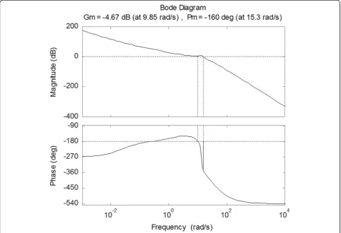
According to Eq. (3), the corresponding open-loop bode curve can be obtained, as shown in Fig. 1.
Where the amplitude crossover frequency is ωc= 13.685 rad/s, the phase stability margin isγ=−160.144°, the phase crossover frequency isωg= 8.683 rad/s, and the gain stability margin ish= 0.342, respectively.
According to the stability criterion of minimum phase system, the simulated amplitude crossover frequencyωcis larger than phase crossover frequencyωg. It indicates that the original control system is unstable at high altitudes.
Meanwhile, the oscillation amplitude and frequency is large, which also means the control system is unstable. The adjusting time of the system is too long for the cross-over frequency is too low, which results in the response of the system to instructions being slow [1].
3 Design of the lag-lead emendation network
3.1 Emendation unit analysis for the original system
Autopilot is important to improve the stability and dynamic performance of the original control system, but
Fig. 1Open-loop bode diagram of the control system within 3 s
Gkð Þ ¼s ½Wεð Þs WDð Þ þs G sð ÞWKΘ_ð Þs WYð Þs
¼ 204
0:05sþ1
0:455sþ1
1:5 0ð :045sþ1Þð0:022sþ1Þþ
3:31sþ0:0678 s2
23:11 s2þ1:93sþ121:13
1 s2 ≈ 204
0:05sþ1
0:455sþ1
1:5 0ð :045sþ1Þð0:022sþ1Þþ 3:31
s
23:11 s2þ1:93sþ121:13
1 s2
¼s3 0:0037s3þ1430:4s2þ3152sþ76:49 0:05sþ1
ð Þð0:045sþ1Þð0:022sþ1Þðs2þ1:93sþ121:13Þ
it needs completely redesign of the missile. Therefore, autopilot is not suitable in the original control system. In this paper, we proposed a method to improve the stability and dynamic performance of the original control system, in which the framework of the original control system is unchanged. The content of the instructions generated by control box is modified. In fact, the instructions are digital and easy to change. The best way to modify the instruc-tions of the control box is to modify the emendation unit.
Specifically, the improvement to the missile control system includes three steps [2].
(1)Build the transfer function of the control loop; (2)Design the emendation unit in frequency domain; (3)Validate the design via trajectory simulation.
The transfer function of the over shoot network unit in the original control system can be represented as
WDð Þ ¼s K 0:455sþ1
0:045sþ1
ð Þð0:022sþ1Þ ð4Þ
Due to Eq. (5), the emendation unit belongs to lead emendation, which can provide with positive phase angle and higher cutoff frequency. Therefore, the system dy-namic performance can be enhanced. But the promotion of the phase stability margin γ is not obvious, resulting in the smaller phase stability margin for the emendation unit and lower stability [3].
arctan0:455
The open-loop phase stability margin γ is merely −160.15°. Larger phase stability margin γ is needed and the cutoff frequency is not too small.
According to the empirical data of the classical control theory, lead emendation can provide positive phase angle and increase the cutoff frequency. But it can only provide phase stability margin about 40° to 60°; the lag emendation decrease the cutoff frequency for a larger phase angle. Therefore, we need to combine the lead and lag emendation together to increase the system phase stability angle and enhance the stability.
3.2 Bode diagram design of the lag-lead emendation 3.2.1 Design requirement for emendation network
The transfer function of the lag-lead emendation network can be written as
Gcð Þ ¼s KGc1ð Þ s Gc2ð Þs
In the design process, adjustment parameters of the characteristic points are designed separately. Then, the
emendation parameters at each time points in the flying process are calculated with linear interpolation. The design requirements are shown in below.
(1)To keep the gain stability marginh, the phase stability marginγis not less than 30°;
(2)To avoid resonance of the missile body, the close-loop cutoff frequency must be less than 0.3 times of the inherent frequency of the missile body,
ωc≤14.13 rad/s;
(3)To ensure the missile not falling on the ground in the uncontrolled flying stage, the system overshoot needs as small as possible.
3.2.2 Procedure for emendation network design
According to classical automatic control theory, the procedure for design phase lag emendation unit using bode diagram is shown as follows [4, 5].
(1)Calculate the open-loop gainKsatisfying the performance requirement of given error coefficients. (2)Plotting the system bode diagram before
emendation, while calculate the amplitude stability marginLm(Gm), crossover frequencyωgof–π, phase stability marginγ(Pm), and cutoff frequency
ωc1(ωcp). Check whether the requirements are satisfied. If not, continue to the next step. (3)Determine the parameters of transfer function for
the lag emendation unit:
Gc1ð Þ ¼s
1þT1s
1þβT1s ð
7Þ
Where these parameters can be chosen in engineering as follows:
1 T1¼
0:1ωc1 β¼8∼10
(4)Choose a new system cutoff frequencyωc2to make the phase provided by lead emendation unit satisfying the requirement of system phase stability marginγ. Meanwhile, the total amplitude frequency attenuation of the original system add the lag emendation unit reaching 0 dB, which means the L curve crosses the horizontal coordinate axis atωc2. (5)Determine the parameters of transfer function for
the lead emendation unit:
Gc2ð Þ ¼s
1þT2s
1þαT2s ð
8Þ
20 logα¼Lðωc2Þ ð9Þ
L(ωc2)(expressed by dB) is the amplitude frequency characteristic of the original system plus lag emendation unit. Whereωc2andT2are shown in below.
(6)Plot the system bode diagram after emendation and check system frequency domain performance. (7)Build close-loop system and validate the
perform-ance of the system.
3.2.3 Calculate the parameters of the emendation network
We will analyze the open-loop gain G(s) for the original guidance loop at 3 s of missile flying. For the emend-ation unit is not added to this moment, therefore, it is not reasonable to design the emendation network when the gravity compensation is added to the transfer func-tion [6]. The gravity-compensating unit is deleted when designing emendation network, for gravity-compensating instruction is disturbing signal in the guidance loop and does not affect the properties of the system itself. The gravity-compensating instruction is added to the guidance loop in system performance simulation. The open-loop transfer function can be represented as
G′
According to the method above, the lag-lead emend-ation procedure is realized in Matlab environment. First, design the lag unit:
According to the code above, the transfer function of the lag emendation network can be obtained:
Gc1ð Þ ¼s
0:8333sþ1
7:083sþ1 ð12Þ
Substitute the transfer function above into the transfer function of the original system to modify the original
transfer function. The Matlab code of design lead emendation network is below.
According to the code above, the transfer function for the lead emendation network is
Gc2ð Þ ¼s
1:232sþ1
0:1225sþ1 ð13Þ
Therefore, the transfer function of the emendation unit is
Gcð Þ ¼s KGc1ð Þ s Gc2ð Þs
3.2.4 Bode diagram check in frequency domain
Substitute the modified transfer function into the ori-ginal guidance loop and the transfer function of the whole system can be obtained:
Gkð Þ ¼s ½Wεð Þs Gcð Þ þs G sð ÞWKΘ_ð Þs WYð Þs
Analyze the modified transfer function in frequency domain.
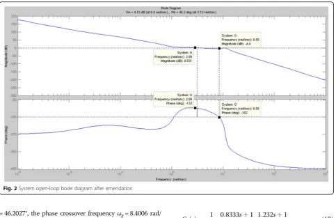
Output the system open-loop bode diagram after emend-ation, as shown in Fig. 2. WhereMis open-loop amplitude margin (unit, dB) andPis phase margin (unit, deg)
According to the figure above, the amplitude crossover frequency isωc= 3.1191 rad/s, the phase stability marginγ
% Open-loop gain K= 1/1.65;
% Lag emendation unit wc= 12; beta = 8.5; T= 1/(0.1*wc); betat= beta*T; Gc1 = tf([T 1],[betat 1])
% Lead emendation unit
den1 = conv([1 0 0 0],[1 1.93 121.13]); den2 = conv([7.083 1],[0.05 1]); den = conv(den1,den2); num = conv([0 4714.7],[0.8333 1]); sope = tf(num,den);
gama = 50;wc = 12; [Gc] = leadc(1,sope,[gama])
den1 = conv([1 0 0 0],[1 1.93 121.13]); den2 = conv([0.05 1],[7.083 1]); den3 = conv(den2,[0.1225 1]); den = conv(den1,den3);
num = 23.11.*[127.98 84.66 150.91 3.31]; G = tf(num,den);
bode(G) margin(G)
= 46.2027°, the phase crossover frequencyωg= 8.4006 rad/ s, and the amplitude stability margin ish= 1.6856.
According to the results above, γ= 46.2027° satisfies the commonly used 30°–70°criterion in engineering de-sign and the crossover frequency is indeed less than 14.13 rad/s satisfying the requirement above.
When the missile flied 7 s, only the second order oscil-lation block changed and the code modifies work that is omitted here. After analysis, it can be concluded that the transfer function of the emendation unit satisfies the sta-bility condition in frequency domain.
In short, the lag-lead emendation unit based on bode diagram can satisfy the control system stability of the missile in high-altitude environment.
4 Circuit design of the emendation network For emendation network design, circuit design is needed to achieve the final goal. In engineering, the circuit is usually emendation equipment composed by operational amplifier and resistor-capacitor network [7–10]. We will design active emendation device for the lag-lead emendation network.
This kind of lag-lead emendation network can be expressed in the following equation.
Gcð Þ ¼s G0 T2sþ1 T1sþ1
T3sþ1
T4sþ1 ð
16Þ
Considering the transfer function of the lag-lead emend-ation, the above equation can be expressed as follows.
Gcð Þ ¼s 1
1:65
0:8333sþ1 7:083sþ1
1:232sþ1
0:1225sþ1 ð17Þ
The value of each parameter can be obtained: G0= 0.606,T1= 7.083,T2= 1.232,T3= 0.8333, andT4= 0.1225 The logarithmic amplitude frequency curve of this kind of transfer function is shown in Fig. 3. From the curve, the performance of the emendation network in the frequency domain can be seen.
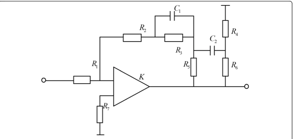
The corresponding circuit of the active emendation device for this kind of transfer function is shown in Fig. 4.
According to the basic knowledge of the circuits, the following proximity equations can be obtained using virtual short and virtual fault theory of the amplifier.
G0¼R2þR3R1þR5 T1¼R3C1 T2¼½ðR2þR5Þ==R3C1 T3¼R5C2 T4¼
R4T3 R4þR6
ð18Þ
Substitute C1= 1μF, C2= 10μF, R4= 10Ω, and R7= 1KΩinto the above equation, and the value of the resist-ance and the capacitresist-ance is R1= 14.3MΩ, R2= 7MΩ, R3 = 1.5KΩ, R5= 83KΩ, and R6= 58Ω.The magnification of the amplifier isK= 50.
From the above analysis, the value of each element is determined. According to the current and voltage of the circuit, the components of the circuit can be obtained.
5 Conclusions
In order to improve the stability of a certain missile in highland environment, the lag-lead emendation network is designed. The stability of the control sys-tem is checked using bode diagram based on fre-quency domain analysis. The simulation results show that the designed emendation network can improve
the stability of the control system. The circuit imple-mentation of the emendation network is analyzed and the values of the components in the circuit are given. Electromagnetic shielding, disturbance of dif-ferent wire, or the voltage matching situation needs to be considered in the implementation process of the circuit. These factors will cause the circuit
Fig. 3Logarithmic amplitude frequency characteristic curve
occurring minor change. Therefore, in the process from emendation network to actual circuit, there are still many specific problems which need to be fur-ther studied.
Acknowledgements
This research was supported the by National Natural Science Foundation of China under Grant No. 1494, 61602346.
Competing interests
The authors declare that they have no competing interests.
Publisher's Note
Springer Nature remains neutral with regard to jurisdictional claims in published maps and institutional affiliations.
Author details
1Shijiazhuang Mechanical Engineering College, Shijiazhuang 050003, China. 2
Tianjin Key Laboratory of Wireless Mobile Communications and Power Transmission, Tianjin Normal University, Tianjin 300387, China.3College of
Electronic and Communication Engineering, Tianjin Normal University, Tianjin 300387, China.
Received: 16 November 2016 Accepted: 1 March 2017
References
1. X Guo, Z Kong, Z Wang, Research on the method of simulation modeling on the control system of certain missile, inIMCCC, 2011, pp. 909–911 2. W Jiang, G Dong, Discussion on the anti-tank missile simulation experiment.
Technol. Found. Natl. Defense7, 55–56 (2007)
3. J Chen, H Fu, Dynamic consistency test method for air-to-air missile simulation results. J. Syst. Simul.20(19), 5121–5124 (2008)
4. Z Wu, X Xia, B Zhu, Model predictive control for improving operational efficiency of overhead cranes. Nonlinear Dynamics79(4), 2639–2657 (2008)
5. Z Wu, X Xia, Optimal motion planning for overhead cranes. IET Control Theory Appl.8(17), 1833–1842 (2010)
6. Z Koruba, L Nocon, Programmed control of the flat track anti-tank guided missile, inProceedings of the 15th international Carpathian control conference, 2014, pp. 237–242
7. Z Li, K Liu, Y Zhao, Y Ma, MaPIT: an enhanced pending interest table for NDN with mapping bloom filter. IEEE Commun. Lett.18(11), 1423–1426 (2014) 8. Z. Li, L. Song, H. Shi, "Approaching the capacity of K-user MIMO interference
channel with interference counteraction scheme". Ad Hoc Networks.
58,286-291 (2017)
9. Z. L, Y. Chen, H. Shi, K. Liu,“NDN-GSM-R: a novel high-speed railway communication system via named data networking”. EURASIP J Wireless Commun Netw. (48), 1–5 (2016).
10. X. Liu, Z. Li, P. Yang, Y. Dong,“Information-centric mobile ad hoc networks and content routing: a survey”. Ad Hoc Networks.58, 255-268 (2017)
Submit your manuscript to a
journal and benefi t from:
7Convenient online submission
7Rigorous peer review
7Immediate publication on acceptance
7Open access: articles freely available online
7High visibility within the fi eld
7Retaining the copyright to your article