Volume 4, No. 6, May 2013 (Special Issue)
International Journal of Advanced Research in Computer Science
REVIEW ARTICAL
Available Online at www.ijarcs.info
CONFERENCE PAPER
Traffic Square Management System
Sujata V. Padole
Dept. Name of Electronics Engineering,
Dr. Bhahusaheb Nandurkar College of Engineering Technology Yavatmal, India [email protected]
Abstract: If the traffic is more on one side and less on other side so there all way a waste of time and fuel on the traffic signal. Which is serious problem now day so there an need to have an intelligent traffic system which can detect the amount of traffic and make the change accordingly by using sensor and tranducer. Also by using motion detection camera at the lane we can find out the vehicle owner who break the traffic rules at the signal.
Keywords: ANPR,Scheduling OCR, DIP, Context switch, IR Radiation,TSOP
I. INTRODUCTION
A. Present Aspects:
Nowadays the number of road accidents are increasing day by day. It has become essential that we look for measures which could decline the rate of accidents. Snaking queues of vehicles on almost all roads were a common sight led to the traffic jams. According to the officials at the India Meteorological Department (IMD), Battling the chaos on the logged roads, most office goers said they left home earlier than usual to escape the morning rush, but were still caught in the traffic jam. Traffic signals at many places functioning leading to further trouble faced by commuters and office goers traveling from one part of the city to the other. “The situation would not change until or unless we have better intelligent traffic signal” .“At our end, we have deployed the entire strength of the traffic police on roads to facilitate vehicular flow and are taking all necessary measures,” Amid all the frustration, some rickshaw and auto drivers, had a field day fleecing helpless commuters.
B. Need Of Traffic System Modification:
Transportation research has the goal to optimize transportation flow of people and goods. As the number of road users constantly increases, and resources provided by current infrastructures are limited, intelligent control of traffic will become a very important issue in the future. However, some limitations to the usage of intelligent traffic control exist. Avoiding traffic jams for example is thought to be beneficial to both environment and economy, but improved traffic-flow may also lead to an increase in demand.
There are several models for traffic simulation. In our research we focus on microscopic models that model the behavior of individual vehicles, and thereby can simulate dynamics of groups of vehicles. the number of road accidents are increasing day by day. If the traffic is more on one side and less on other side so there all way a waste of time and fuel on the traffic signal. Which serious problem
now day so there an need to have an intelligent traffic system which can detect the amount of traffic and make the change accordingly.
II. OBJECTIVE
As number of accidents occurs due to improper traffic management systems this project fulfils the need of new system that decreases the accidents by managing proper density at the traffic signal. Spending much time on traffic signal also leads to wastage of fuel alongwith time. This project also helps in overcoming with this problem. Also here cameras are used so that the person that breaks the signal can automatically be caught by displaying the number from vehicle number plate directly in the control room. There are several models for traffic simulation. In our research we focus on microscopic models that model the behavior of individual vehicles, and thereby can simulate dynamics of groups of vehicles. Where based on using devices in vehicles that would use proprietary protocols to identify a vehicle as it passed under a gantry over the roadway. More recently there has been a move to standardize that has been promoted for vehicle safety by the Intelligent.
III. CONTROLLING UNIT
IV. WORKING
The infrared object counter can be installed at the entry of vehicle entering any venue. The counter uses an infrared transmitter-receiver pair and a simple, low cost calc. It works even in the presence of normal light. The maximum detection range. That means the transmitter and the receiver are to be installed. No focusing lens is required.
Powered by a 3v battery, the transmitter circuit comprises IC 555 (IC1) which is wired as an a stable multivibrat or with a center frequency of object 38kHz and two infrared light emitting diodes LEDs. The receiver circuit is powered by a 5v regulated power supply built around transformer X1, bridge rectifier comprising diodes D1 through D4 and regulator IC2. It uses an infrared receiver (IR) module (RX1), Optocoupler (IC3) and a simple calculator.
When switch S1 is in ‘on’ position, the transmitter circuit, IR receiver module TSOP1738, which is commonly used in colour televisions sensing the IR signals transmitted from the TV remote, is used as the sensor.
A. Monitoring process:
The first stage is completed at the lane location itself which consist of the rising and decreasing the signal light period with the help of the microcontroller. The microcontroller works as per the way. A database manager organizes a related collection of data so that information can be retrieved easily. A database is a collection of related data. A database management System (DBMS) or database manager is a program that sets up, or structures, a database. Database managers are used by all kinds of people, from teachers to police officers.
Figure.1. Block diagram of transmission information from lane location to remote computer
B. Sensors:
The IR radiations transmitted from the transmitter is continuously received by the receiver section ,it performs the pair of tasks .Checking for the density of the traffic by developing the IR spectrum of frequency 38Khz. Checking for, if there is any vehicle is breaking the traffic rule. Most of Security System uses light or micro switch, magnetic sensor to detect the signal. Here is a new type of security system that uses Infrared rays to detect the signal. This
signal is invisible signal. Therefore once we install the circuit we need not require any setting except to watch the power supply.
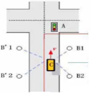
Figure. 2 Pair of transmitter receiver mounted on lane sides to control the traffic
C. Microcontroller:
The microcontroller programming is done in such way to increase the timing of the green signal of the lane where the traffic is dense and simultaneously reducing the time period of the remaining other. Microcontroller sends the signal to the light and the camera whether to be ON / OFF. Also it transfers the data from the lane location to remote computer. The second stage includes, transmitting captured data from the lane location to the remote computer for the further processing, from which we get the complete information about the vehicle and vehicle owner and the action to be taken in respect to the circumstances.
Figure. 3. Required Remote computer monitor screen display
D. Trigger:
CONFERENCE PAPER
on microscopic models that model the behavior of individual vehicles, and thereby can simulate dynamics of groups of vehicles. Where based on using devices in vehicles that would use proprietary protocols to identify a vehicle as it passed under a gantry over the roadway. More recently there has been a move to standardize that has been promoted for vehicle safety by the Intelligent.
E. Character Recognition System:
Image analysis uses a set of pattern recognition techniques to enable computer systems to recognize and interpret images. Image analysis consists of two stages: image processing and analysis, and pattern recognition. Image processing and analysis includes steps such as image repair to improve quality and usability issues, and feature extraction for the subsequent pattern recognition stage. Pattern recognition includes an area of interest location within the original image, data extraction and the validation of an existing representation or context.
Automatic number plate recognition mass is a surveillance method that uses optical character recognition on images to read the license plates on vehicles[2]. They can use existing closed-circuit television or road-rule enforcement cameras, or ones specifically designed for the task.
Figure.4. Block diagram for optical character recognition
V. TECHNOGOLY
ANPR uses optical character recognition (OCR) on images taken by cameras. When Dutch vehicle registration plates switched to a different style in 2002, one of the changes made was to the font, introducing small gaps in some letters (such as P and R) to make them more distinct and therefore more legible to such systems. Some license plate arrangements use variations in font sizes and positioning ANPR systems must be able to cope with such differences in order to be truly effective. More complicated systems can cope with international variants, though many programs are individually tailored to each country. The cameras used can include existing road-rule enforcement or closed-circuit television cameras, as well as mobile units, which are usually attached to vehicles.
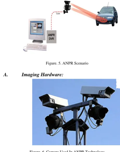
Figure. 5. ANPR Scenario
A. Imaging Hardware:
Figure. 6. Camera Used In ANPR Technology
At the front end of any ANPR system is the imaging hardware which captures the image of the license plates. The initial image capture forms a critically important part of the ANPR system which, in accordance to the Garbage In, Garbage Out principle of computing, will often determine the overall performance.
License plate capture is typically performed by specialized cameras designed specifically for the task. Factors which pose difficulty for license plate imaging cameras include speed of the vehicles being recorded, varying ambient lighting conditions, headlight glare and harsh environmental conditions. Most dedicated license plate capture cameras will incorporate infrared illumination in order to solve the problems of lighting and plate reflectivity.
A camera that makes use of active infrared imaging (with a normal colour filter over the lens and an infrared illuminator next to it) benefits greatly from this as the infrared waves are reflected back from the plate. This is only possible on dedicated ANPR cameras, however, and so cameras used for other purposes must rely more heavily on the software capabilities. Further, when a full-colour image is required as well as use of the ANPR-retrieved details it is necessary to have one infrared-enabled camera and one normal (colour) camera working together.
slow-moving traffic, or when the camera is at a lower level and the vehicle is at an angle approaching the camera, the shutter speed does not need to be so fast. Shutter speeds of 1/500 of a second can cope with traffic moving up to 40 mph (64 km/h) and 1/250 of a second up to 5 mph (8 km/h). License plate capture cameras can now produce usable images from vehicles traveling at 120 mph (190 km/h).
To maximize the chances of effective license plate capture, installers should carefully consider the positioning of the camera relative to the target capture area. Exceeding threshold angles of incidence between camera lens and license plate will greatly reduce the probability of obtaining usable images due to distortion. Manufacturers have developed tools to help eliminate errors from the physical installation of license plate capture cameras to take a clearer image of the plates The license plate is normalized for brightness and contrast, and then the characters are segmented to be ready for OCR.
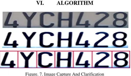
VI. ALGORITHM
Figure. 7. Image Capture And Clarification
There are six primary algorithms that the software requires for identifying a license plate:
a. Plate localization – responsible for finding and isolating the plate on the picture.
b. Plate orientation and sizing – compensates for the skew of the plate and adjusts the dimensions to the required size.
c. Normalization – adjusts the brightness and contrast of the image.
d. Character segmentation – finds the individual characters on the plates.
e. Optical character
recognition.Syntactical/Geometrical analysis – check characters and positions against country-specific rules.
The complexity of each of these subsections of the program determines the accuracy of the system. During the third phase (normalization), some systems use edge detection techniques to increase the picture difference between the letters and the plate backing. A median filter may also be used to reduce the visual noise on the image.
VII. FUNCTIONALITYDOMAIN
VISUAL BASIC is used for implementation of front end. Because VISUAL BASIC is the super set of BASIC LANGUAGE. BASIC is windows Based, it provides graphical user interface (GUI). Since it is GUI application
build in VB are more attractive. VB was launched in 1997 in which local database and remote data base connectivity is possible[4]. VISUAL BASIC is the fastest and easiest way to create applications for programming. VISUAL BASIC provides with a complete set of tools to simplify rapid application development.
“VISUAL” part return to the method to create the graphical user interface (GUI). Instead of writing various lines of code for creating the set its different properties such as shape, color etc. “BASIC” part refers to the BASIC (Beginners All Purpose Symbolic Instruction Code) language. VISUL BASIC has evolved from the original BASIC language and now contains several hundred statements, functions and keyboards, many of which relate directly to the windows GUI. Any beginner can create the application by just learning a few of the keywords.
VIII. APPLICATIONS
A. In Security System:
In public or goods security system the project of square management can be utilized in the way that we can easily monitor the vehicles entering or leaving the high security zone or area. This can be achieved by mounting a camera over the head of entrance gate where each vehicle or visitor can be judged for the security if the database provides a faithful signal then only the gate opens and allow the thing to be in.
B. In Shopping Malls:
In the shopping malls now a days news of theft and cheating has increased. This concept of square management can be implemented in molls to avoid this. This can be done by use of cameras at each stalls coding so that the product picked should be paid at the counter without failure.
C. For Speed:
To provide section control over speed depending upon density of region, to measure average vehicle speed over longer distances.
D. In Banks & Government Offices:
In banks and offices the visitor management can be done by this concept which is definitely going to prevent robberies.
E. In Fuel Filling Station:
This concept can be well implemented for the fuel filling stations as by all time monitoring of the costumers none of them can run away without paying for fuel.
IX. CONCLUSION
In this we propose approaches to controller the multiple traffic light in a City by applying a simple method using sensor communication network and Traffic Light Cameras for display and monitoring City traffic. In this project we also approaches the another aspect of traffic control is controlling traffic light in a way that minimize the time drivers have to wait.
CONFERENCE PAPER
implementation of this concept we can achieve a full control on the regulation and maintenance of traffic from a remote control room via the aid of our monitoring system..
Future aspects of this works is communicating the situation of traffic to the individual of City using LCD display on every traffic unit and vehicle also by transmitting audio message using and wireless transmitting.
X. REFERENCES
[1]. B.L. Tseng Ching-Yung Lin and J.R. Smith. Real-time video surveillance for traffic monitoring using virtual line analysis. Multimedia and Expo, 2002. ICME ’02. Proceedings, 2002 IEEE International Conference on volume 2, 26-29 Aug. 2002 PP-541-544
[2]. G. Ogasawara, B. Rao, and S. Russell. Towards Robust Automatic Traffic Scene Analysis in
Real-Time. Pattern Recognition, 1994. Vol.1-Conference A: Computer Vision and Image Processing, Proceeding of the 12th INPR International Conference on Volume 1,9-13 Oct. 1994. PP-126-131.
[3]. Rafael C. Gonzalez and Richard E. Woods, “Digital Image Processing”,Prentice Hall.
[4]. Programming in visual basic 6.0 by Julia Case Bradley and Anita c. Millspaugh , Tata Mc Graw-Hill edition 2000, chap no 11 Accessing Database file, topic VB and data files, using the data controls, updating the database files, PP. 442-445, 459, 460