IJEDR1401226
International Journal of Engineering Development and Research (www.ijedr.org)1269
Comparison of One-Cycle Control and Conventional
Control Method for Buck and Boost Converter
1
Vaidya Chirayu Pankaj,
2Patel Priyanka Jayantilal,
3Prof. Shabbir S. Bohra
1 P.G. student, 2 P.G. student, 3 Asst. Professor
Electrical Engineering Department, Sarvajanik College of Engineering & Technology, Surat, India 1[email protected], 2[email protected], 3[email protected]
________________________________________________________________________________________________________
Abstract— This paper demonstrate that switching converters based on One-Cycle Control strategy reject input-voltage
perturbations in only one switching cycle and follow the control reference very quickly. The results are compared with conventional PWM control technique in terms of dynamic response. Simulation has been carried out to verify the results on MATLAB platform.
Index Terms— Integrator, One-cycle control (OCC), Nonlinear control, Pulse width modulation (PWM), Buck-Boost
converter.
I.INTRODUCTION
The switched mode dc-dc converters are some of the simplest power electronic circuits which convert one level of electrical voltage into another level by switching action. These converters have received an increasing deal of interest in many areas. The analysis, control and stabilization of switching converters are the main factors that need to be considered.
The control method that gives the best performances under any conditions is always in demand. Switching converters are pulsed nonlinear dynamic systems. There is no standard way to model nonlinear system. At present, most control schemes are approached by first linearizing the governing equations and then applying a linear feedback technique. This approach greatly restricts the capability of switching nonlinear systems. One-cycle control is non linear control technique to control the nonlinear pulsed switching converter.
It is not satisfaction at DC/DC converters by conventional feedback control. Conventional feedback control[1] is slow to respond the disturbance of power source and a large number of switching cycles is required before the steady-state is regained. The commonly used control methods for dc-dc converters are pulse width modulated (PWM) voltage mode control, PWM current mode control with proportional (P), proportional integral (PI), and proportional integral derivative (PID) controller. These conventional control methods like P, PI, and PID are unable to perform satisfactorily under large parameter or load variation.
Therefore, nonlinear controllers like One-Cycle Control come into the picture for controlling output voltage of dc-dc converters. The advantages of these nonlinear controllers are their ability to react suddenly to a transient condition. The objective of this work is to achieve large-signal nonlinear control of switching converters. The motivation is that pulsed nonlinear systems under pulsed nonlinear control should be more robust, have faster dynamic response, and better input-perturbation rejection than the same system under linear control. OCC can be used in applications such as AC/DC converters, active power filters, grid connected inverters, power factor correction, var compensation.
Section II describes the brief introduction to DC-DC converter. Section III describes the PWM technique. Section IV describes One-cycle control technique. Section V describes the simulation procedure and comparisons. Finally conclusions are given in section VI.
II.DC-DC CONVERTER
These converters have received an increasing deal of interest in many areas. This is due to their wide applications like power supplies for personal computers, office equipments, appliance control, telecommunication equipments, DC motor drives, automotive, aircraft, etc.[1] The analysis, control and stabilization of switching converters are the main factors that need to be considered. Many control methods are used for control of switch mode dc-dc converters and the simple and low cost controller structure is always in demand for most industrial and high performance applications.
A. Basic Buck converter
IJEDR1401226
International Journal of Engineering Development and Research (www.ijedr.org)1270
Fig. 1 Basic Buck ConverterWhen the switch is ON, the diode is OFF, and the diode-voltage vs is equal to the input voltage vg. When the switch is OFF, the diode is ON, and the diode voltage vs is zero. The DC line-input voltage is chopped by the switch resulting in a chopped
waveform vs. The average, or DC, of this waveform is Vs ,
∫
The LC low-pass filter transmits this value to the output while rejecting most of the undesired switch frequency fs. Therefore, the output voltage contains the desired DC value Dvg and a small residual switch ripple. The buck converter has a conversion rate
equal to its duty-ratio D. By controlling the duty-ratio D, the output DC voltage is controlled.
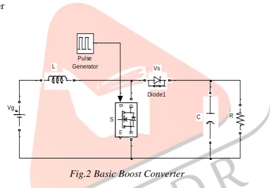
B. Basic Boost converter
Fig.2 Basic Boost Converter
When the switch is OFF, the diode is ON, the diode voltage is equal to the difference between input and output voltage.
∫
When the switch is OFF, the diode is ON, and the diode voltage vs is zero.[2]
III.PULSEWIDTHMODULATIONTECHNIQUE
In PWM control, the duty ratio pulses are produced by comparing control reference signal with a saw-tooth signal. As a result the control reference is linearly modulated into the duty ratio signal. A PWM control diagram is shown in Fig. 3. The duty ratio is modulated in a direction that reduces the error.[1]
Fig. 3 PWM applied to switching converter
Vg
Vs L
C R
g
m
D
S
S Pulse Generator
IJEDR1401226
International Journal of Engineering Development and Research (www.ijedr.org)1271
If the power supply voltage is perturbed means small change occurs, the duty ratio control does not see the change instantaneously since the error signal must change first. Therefore, the output voltage jumps up and the typical output voltage transient overshoot will be observed at the output voltage. Then the error produced in the output voltage is tuned with PI controller and compared with the saw tooth signal to control the duty ratio pulses. The duration of the transient is dictated by the loop-gain bandwidth.IV.ONECYCLECONTROLTECHNIQUE
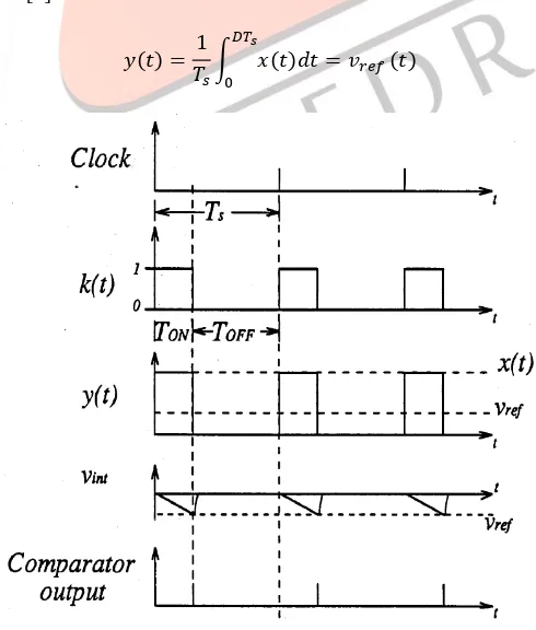
For a constant frequency switch, Ts is constant. The object of One-Cycle Control is to adjust the switch ON-time TON in each cycle, such that the integrated value of the chopped waveform is constant.[1][3]
The implementation circuit for One-Cycle Control of constant frequency switches is shown in Fig. 4. The key component of One-Cycle Control technique is real time integrator. The real time integration is started the moment when the switch is turned ON by the fixed frequency clock pulse. The integration value, vint =1/Ts, is compared with the control signal vref(t) in real time. At the instant when the integration value vint reaches the control signal vref(t) , the controller sends a command to a switch, which forces a switch to change from the ON state to the OFF state. At the same time controller resets the real time integrator to zero to prepare for the next cycle[1]. The duty ratio D of the present cycle is determined by following equation.
∫
Fig. 4 The One-Cycle Controlled constant frequency switches
Since the switch period Ts is constant and the duty ratio is controlled, the average value of the waveform at the switch output y(t) is guaranteed to be in each cycle.[4]
∫
IJEDR1401226
International Journal of Engineering Development and Research (www.ijedr.org)1272
V.SIMULATIONSANDRESULTS
i. Buck converter using One-Cycle Control and conventional control method
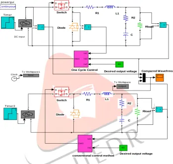
Fig. 6 shows the simulation block diagram of buck converter using One-Cycle Control and Conventional control method. The output voltages using both the methods are compared and shown in figure 6.
Fig. 7 shows the subsystem of One-Cycle Control method which is simply made up of SR flipflop, comparator and resettable integrator and clock. In One-Cycle Control diode voltage is used as switched variable and control reference is given as constant 40 V. Dc input voltage is perturbed from 50 V to 60 V.
Fig. 8 shows the subsystem of conventional control method (PWM control), in which output voltage and reference 40 V are compared and error sent to the PI controller and then output of PI controller compared with triangular waveform. This will give the gate pulses that control the switch. Here also DC input voltage is perturbed from 50 V to 60 V. and all other parameters for both the methods are same.
Fig. 6 Model of buck converter using One-Cycle Control and conventional control
Fig. 7 Subsystem (Conventional control method)
Desired output voltage
Desired output voltage
R1 L1 R2 C R1 L1 R2 C Rload
conventional control method One Cycle Control
Diode Rload Diode Switch Switch Compared Wavefrms DC input C ontinuous powergui In1 In2 In3 Out1 In1 In2 Out1 v + -v + -v + -v + -time T o Workspace1
output T o Workspace
IJEDR1401226
International Journal of Engineering Development and Research (www.ijedr.org)1273
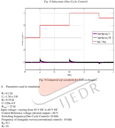
Fig. 8 Subsystem (One-Cycle Control)Fig. 9 Compared o/p waveform for both techniques
A. Parameters used in simulation
R1=0.2 Ω L1=1.38 e-3H R2=0.39 Ω C=220e-6 F Rload = 25 Ω
Input voltage= varying from 50 V DC to 60 V DC Control Reference voltage (desired output) =40 V Switching frequency(One-Cycle Control)=10 kHz
Frequency of triangular waves(conventional control)= 10 kHz Kp=0.1
Ki=10
B. Result analysis
As shown in Fig. 9 the input dc voltage is perturbed in different steps from 50 V to 60 V.
The purple waveform shows the output voltage using One-Cycle Control method. The One-Cycle Controller rejects the input voltage perturbation and follow the control reference in one cycle and gives desired output 40 V.
The black colored waveform shows the output voltage using conventional control method. As shown at t=0.2&0.4&0.6 second this method will also give desired output 40 V but it takes long time to reach in steady state condition.
So, we can say that One-Cycle Control method gives more effective control and input perturbation rejection compared to conventional method.
ii. Boost converter using One-Cycle Control and conventional control method 1
Out1 R
[S]
!Q Q
SR flipflop
1 s
Resettable Integrator <=
Comparator Clock
3 In3
2 In2 1
IJEDR1401226
International Journal of Engineering Development and Research (www.ijedr.org)1274
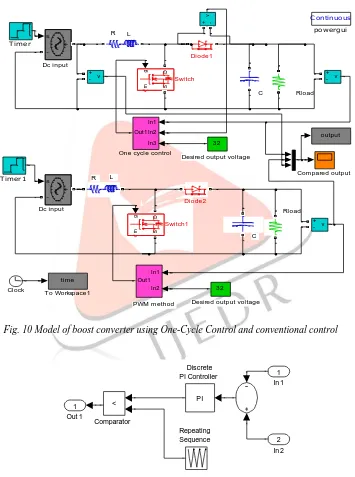
Fig. 10 shows the simulation of boost converter using One-Cycle Control and Conventional Control method. The output voltages using both the methods are compared and shown in Fig. 13.Fig. 12 shows the subsystem of One-Cycle Control method In which diode voltage is used as switched variable and control reference is given as constant 32 V. Dc input voltage is perturbed from 20 V to 26 V.
Fig. 11 shows the subsystem of conventional control method (PWM control), in which output voltage and reference 32 V are compared and error sent to the PI controller and then output of PI controller compared with triangular waveform. This will give the gate pulses that control the switch. Here also Dc input voltage is stepped perturbed from 20 V to 26 V. and all other parameters for both the methods are same.
Fig. 10 Model of boost converter using One-Cycle Control and conventional control
Fig. 11 Subsystem (Conventional control method) PWM method
Desired output voltage
Desired output voltage
R L
C Rload
R L
C Rload Dc input Dc input C C ontinuous powergui v + -v + -v + - v + -time
T o Workspace1
output Timer1 Timer g m D S Switch1 g m D S Switch In1 In2 Out1 In1 In2 In3 Out1
One cycle control
IJEDR1401226
International Journal of Engineering Development and Research (www.ijedr.org)1275
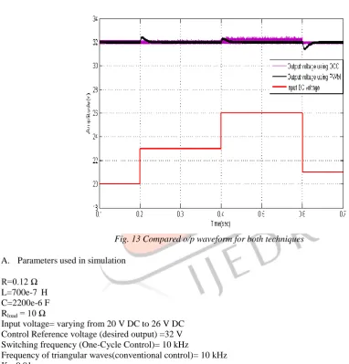
Fig. 12 Subsystem (One-Cycle Control)Fig. 13 Compared o/p waveform for both techniques
A. Parameters used in simulation
R=0.12 Ω L=700e-7 H C=2200e-6 F Rload = 10 Ω
Input voltage= varying from 20 V DC to 26 V DC Control Reference voltage (desired output) =32 V Switching frequency (One-Cycle Control)= 10 kHz
Frequency of triangular waves(conventional control)= 10 kHz Kp=0.01
Ki=1
B. Result analysis
As shown in Fig. 13 the input dc voltage is perturbed in different steps from 20 V to 26 V.
The purple colored waveform shows the output voltage of boost converter using One-Cycle Control method. One-Cycle Controller reject the input voltage perturbation and follow the control reference in one cycle and gives constant desired output 32 V.
The black colored waveform shows the output voltage using conventional control method,which takes long time to reach in steady state condition.
iii. Power Source Perturbation Analysis
Out 1 1 Unit Delay 1
z 1 Relational
Operator
>= Integrator 1
1
s Gain 1
-1
Clock
Bistable R [S]
!Q Q
In 3 3 In 2
2
IJEDR1401226
International Journal of Engineering Development and Research (www.ijedr.org)1276
In the above simulation waveforms we can see, both converters under PWM control has slow dynamic performance in regulating the output in response to the change in input voltage. Output voltage is changed due to input voltage perturbation. But under one-cycle control, the output voltage is not change even if the power source having a disturbance. So one-one-cycle control technique is excellent to reject the power source disturbance.VI.CONCLUSION
Theoretically, converters with One-Cycle Control are capable of rejecting the input voltage perturbations, and the diode-voltage is able to follow the control signal instantaneously, within one cycle. The experimental circuits of a buck and a boost converter in this work show a very close match between the simulations and the theoretical predictions. PWM and one-cycle control techniques are compared in terms of dynamic response. The simulation results have demonstrated that, under both control techniques switching converter can have good steady state performance but One-Cycle Control shows better performance than PWM control in dynamic response and thereby overcomes the inherent drawback of PWM control.
ACKNOWLEDGMENT
The authors sincerely thank to Electrical Engineering Department, SCET, Surat for providing continuously guidance and other facility to carry out this work.
REFERENCES
[1] K. M. Smedley, S.Cuk, “One-Cycle Control of Switching Converters, IEEE Trans. on Power Electronics, vol. 10, no.6,November 1995, pp. 625-633.
[2] E. Santi, S. Cuk, “Modeling of One-Cycle Controlled Switching Converters”, INTELEC’92, Washington, DC, Oct. 1992, pp. 131-138.
[3] K.M.Smedley and Slobodan Cuk, "One- Cycle Control of Switching Converters” IEEE PESC, 1991 Record, pp .888- 896.