377 IJSTR©2019
Performance And Comparative Study Of Exhaust
Gas Recirculation Cooler With Plain Tube And
Plain Tube With Vortex Generator Fin Using
Computational Fluid Dynamics
Ibrahim Hussain Shah, Vivek Sharma
Abstract— The popularity of diesel engines have increased not only in commercial vehicles but also in passenger cars because it provides more fuel economy and higher power compared to petrol engines. Thoughtful efforts are being made in order to diminish the quantity of NOx released by automobiles, principally those using Diesel Engines. Exhaust Gas Recirculation (EGR) is one of the most preferred techniques to reduce NOx emission from Diesel Engines. In the EGR technique, a part of an engine’s exhaust gas supplied back to the engine cylinders. In this analysis, comparison is made for plain tube geometry and tube with vortex generator fin using Computational Fluid Dynamics (CFD) simulation and calculations. Among the design of tube geometries used in EGR Cooler simulation, based on the CFD simulation and calculation, we found that the performance of the Plain tube with vortex generator fin for EGR cooler is best in both of them. Also applying Vortex fin at the inlet of the tube surely increases the performance of EGR cooler it is seen in the case of geometry with vortex fin.
Index Terms—Computational Fluid Dynamics, Diesel Engine, Effectiveness, EGR Cooler, Emission, Emission Control, Exhaust gas Recirculation, Heat Exchange, NOx, Performance Comparison, Vortex Fin.
————————————————————
1 I
NTRODUCTIONWITH
increasing global temperature and unenviable climate change, environment pollution became a major concern and, with an increasing number of vehicles on the road, this problem became more chaotic. As automobile emission is a major contributor to air pollution thus, it is a major goal to significantly reduce emission. Under this concern government also created emission norms to check the emission from vehicles, and as the number of vehicles is increasing day by day this leads these norms to grow into more strict emission standards. Hence this became a major objective of automobile researchers and manufacturers to develop and upgrade their previous technologies to perform under these strict emission norms.The popularity of diesel engines is increased not only in commercial vehicles but also in passenger cars because it provides more fuel economy and higher power compared to petrol engines. Thoughtful efforts are being made in order to diminish the quantity of NOx released by automobiles, principally those using Diesel Engines. To control NOx emission two widely available techniques are Exhaust Gas Recirculation and Selective Catalytic Reduction. Out of which Selective Catalytic Reduction is quite an effective method, Selective Catalytic Reduction (SCR) is a progressive active emissions control system that injects a liquid-reducing agent through a special kind of catalyst inserted to the stream of exhaust in diesel engine.
The reducing source is usually automotive-grade urea known as Diesel Exhaust Fluid (DEF), which converts nitrogen oxides into nitrogen, water and a small quantity of carbon dioxide. However, in the current automotive market scenario, it is difficult to implement it on existing road vehicles due to the extensive alteration that must be prepared to the exhaust system and the higher cost of the technique and its maintenance. Therefore the widely preferred method to reduce NOx is Exhaust Gas Recirculation.
Exhaust Gas Recirculation (EGR) is one of the most preferred techniques to reduce NOx emission from Diesel Engines, In the EGR technique, a part of an engine‟s exhaust gas supplied back to the engine cylinders. The main principle of EGR is to recirculate 10% to 30% of the exhaust gases back into the inlet where it got mixed with the fresh air intake and hence O2
concentration is reduced by diluting the charge in intake and lessen the maximum temperature inside the combustion chamber and therefore reduces NOx formation. [1]
2
L
ITERATURE REVIEWYoung-Ho Seo, Hyung- Min Lee, Sang-Kwang Jeon, Tae-Wan Ku, Beon-Soo Kang& Jeong Kim considered a dimple type EGR cooler to improve the efficiency of the heat exchange. The tube they used has several dimples on the tube surface for enlarging the net heat transfer area. They also evaluated the structural integrity of dimple type EGR cooler which is exposed to thermal and pressure-related load using a numerical approach. To reduce the computational cost they used homogenization method in calculation of equivalent elastic and shear moduli that simplifies finite element modeling. They also made an experimental approach in the
Mr Ibrahim H. Shah is currently Assistant Professor at Department of Mechanical Engineering, Institute of Engineering and Technology, DAVV, Indore (M.P.),India Vivek Sharma is currently pursuing Master degree program in Design and Thermal
378
evaluation of heat exchange efficiency of dimple tube type EGR cooler.[2]
Ibrahim H.Shah, Bajrang Singh Kushwah used Computational Fluid Dynamics as well as Analytical method to compare among tube and fin geometries of Exhaust Gas Recirculation cooler. They compared four geometries of different tubes and fins which are triangular fin tube, Rectangular fin tube, Plain tube, and Trapezoidal fin tube. All this model of the tube they used in shell and tube type heat exchanger EGR cooler. They determined that Trapezoidal fin-type tube among four of the model of EGR give extreme heat transfer and hence concluded that effectiveness of trapezoidal fin geometry to be maximum. They also predicted NOx emission for these geometries and found least in the case of trapezoidal fin-type EGR.[3] Ibrahim H.Shah, Avinash Kumar Namdeo performed analysis on two models, the first model with single-pass baffled shell and tube type of heat exchanger in EGR and second model they used tube having same arrangement and spacing as in the previous model but they replaced plain tube with internally finned tubes to increase the internal surface area of tube. They concluded with the help of CFD analysis Simulation that EGR having a tube with internal fin have more effectiveness and have higher heat transfer capability.[4] Ibrahim H. Shah, Bhupendra Singh used Computational Fluid Dynamics to simulate fluid flow field and fluid temperature distribution in EGR cooler. They developed three different models of EGR cooler which are a plain tube, Circular finned tube, and rectangular finned type respectively. Using Analytical study and CFD simulation they concluded that there is increased heat transfer between coolant and exhaust gas for finned type tubes, they observed maximum heat transfer in the rectangular finned tube of EGR.[5]
Ibrahim H. Shah, Pawan Detwal studied the performance of EGR coolers for different tubes and fin geometries, for shell and tube type heat exchanger with four different types of models which are a simple circular tube, a simple tube with internal rectangular fin, the tube with spiral fins and dimple type tube. Out of these four models of tubes, they found that EGR with dimple type tube have maximum effectiveness and hence maximum heat transfer capability. Also, the lowest NOx is predicted in EGR with a dimple type of tube.[6]
Saurabh Kumar, Sourav Kumar used computational fluid dynamics to perform performance analysis on different types of finned tube geometries. They found that the best way to optimize the heat transfer in EGR cooler is by providing finned surfaces inside the tubes. However, using corrugations outside the tube surface also helps them in optimizing the heat transfer. They used three models of tubes for EGR CFD Analysis which is a plain tube; Internal Rectangular finned type and Internal trapezoidal finned tube. They found that rectangular finned tubes in EGR result in maximum effectiveness. [7]
Ibrahim Hussain Shah, Raghvendra S. Bhadoriya, performed CFD Simulation on Stack Type EGR Cooler for Compression Ignition Engine. They studied three different models of EGR cooler, among these three models first one is a traditional shell and tube geometry, the second model is stack type and in the third model, fins are added in stack type geometry. They found that the heat exchange of the stack-type EGR cooler with the added fin is much higher than that of the other models of shell and tube type EGR cooler.[8]
Harilal S. Sorathia, Dr. Pravin P. Rahhod, and Arvind S. Sorathiya studied the effect of Exhaust Gas Recirculation on NOx Emission for various internal combustion. For these analyses they studied effects on five different types of engines, the first engine is fuelled with JATROPHA biodiesel, second is a constant speed diesel engine, third is high duty DI diesel engine, fourth is LPG fuelled diesel engine, fifth is diesel engine with hydrogen with dual fuel. They concluded in the paper that higher EGR rate can be used at lower loads and Lower EGR rate can be used at higher load.[9]
Ming Zheng, Graham T. Reader, J.Gary Hawley reviewed the path and limit to reduce NOx emission from the diesel engine, they also highlighted the impact of EGR on Diesel engine operation and various ways to use EGR are outlined. They finally concluded though using EGR increases wearing in the engine, affects engine durability and performance, EGR is quite the best feasible technique that can be used to reduce NOx intensely.[10]
Iwasaki, Mitsuru, Hara, Junichiro, Honda, Itsuro used a new approach by designing a fin which generates long life vortex to improve the heat exchange from the exhaust gas to the coolant. They used various fin shapes and studied them on the various angle. They found that by adopting new Vortex generation fin technology in EGR, the performance of EGR is increased by 10%.[11]
Krishnan Arjun, Vinay C. Sekar, Balaji J, S.M Boopathi used „base-engine' data to predict by how much NOx emissions would produce for different exhaust gas flow rates, if an EGR system were to be implemented on the engine. And hence studied the Prediction of NOx emission with EGR using the Flame Temperature Correlation Technique. This paper gives a simple methodology for evaluating the effect of EGR on NOx reduction based on the Flame Temperature Correlation, which can easily be implemented in the calculation. The results were matched with experiments and were found to match acceptably for industrial purposes for low to medium loads, speeds and EGR flow rates. [12]
3 I
NITIAL CALCULATION379 IJSTR©2019
which are further used as input values in CFD simulation are calculated also the initial analytical design is made using these calculations.
3.1 Engine Calculation
TABLE1 ENGINE SPECIFICATION
The calculation for a mass flow rate of exhaust [1] The swept volume of the engine;
Volume swept per minute by piston
= 0.020798 m3/sec
When exhaust stroke ends part of exhaust gases left in the clearance volume. At the same time, the inlet valve opens and the exhaust valve closes. Also, at the start of the suction stroke fresh air simultaneously not begin to enter in the cylinder. Therefore, the exhaust gas already in the cylinder expands to fill the volume due to the translation of the piston. The fresh air starts to enter into the engine cylinder when the pressure of left out expanded exhaust gas becomes equal to the inlet pressure of fresh air. The relation between Actual intake volume to the Swept volume is given using volumetric efficiency. Taking volumetric efficiency as 90% we have a relation as
Rate of flow of air into the engine
Mass flow of air into the engine
Cycle Temperature calculation [1]
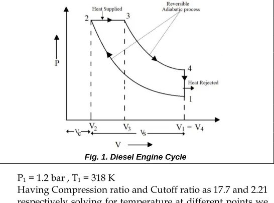
Fig. 1. Diesel Engine Cycle
P1 = 1.2 bar , T1 = 318 K
Having Compression ratio and Cutoff ratio as 17.7 and 2.21 respectively solving for temperature at different points we have
T2 = 1003.73 K
T3 = 2218.24 K
T4 = 987.82 K
3.2 Analytical Design of Exhaust gas Recirculation Heat Exchanger[13]
TABLE2 PROPERTIES OF FLUIDS
TABLE 3
Design Parameters
Surface area of tube
A
t=
πdtl
= 2002.765 mm
23 4 2 10 12 . 3 4 m V l d V s s 60 2 K RPM VS
sec / m 0.0187 3 V V V V S
380
Taking temperature drop of 400 K for the exhaust gas using EGR cooler. Based on the properties of fluids in the EGR cooler and using Energy balance in EGR for both exhaust gas and coolant we have Counter-flow type of Heat exchanger flow we have.
Inlet temperature of exhaust gas Tgi= 987.82 K
Outlet temperature of exhaust gas Tgo = 587.82 K
Inlet temperature of coolant Tci= 318 K
Outlet temperature of coolant Tco =401.31 K
For counter flow heat exchanger θ 1 = Tgi- Tco = 586.51 K
θ2 = Tgo- Tci = 269.82 K
Log Mean Temperature Difference
Heat transferred
2185.47 = 200. A. (407.87) [Taking U= 200 W/m2]
A= 0.0267 m2
No. of tubes required
n = A/At = 13.08
Taking number of tubes = 13 (In integer value) For triangular arrangement of tubes
Pitch = 1.25dt =10.625 mm
Bundle diameter
[k1=0.319 ; n1= 2.142];for single pass triangular tube
arranged Shell and tube Heat Exchanger Shell Diameter = Db + Clearance
= 42 + 3 mm
Shell Diameter = 45 mm
4
T
UBEG
EOMETRIESThe shell and tube type heat exchanger is used in Exhaust Gas recirculation cooler for this in analysis we used two tube geometries which are plain tube and Vortex Generator fin
tube. The shell diameter is of 45 mm and both the tube geometries have 13 such tubes in them.
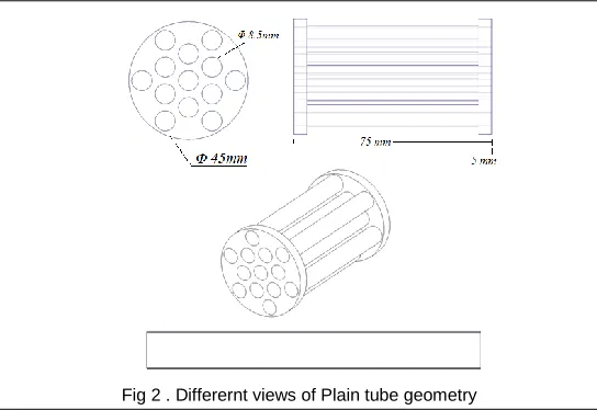
4.1 Plain tube
Based on the heat transfer calculation for design of heat exchanger, the analytical design of the shell and tube type heat exchanger is made with plain tube geometry with 13 tubes.
Fig 2 . Differernt views of Plain tube geometry
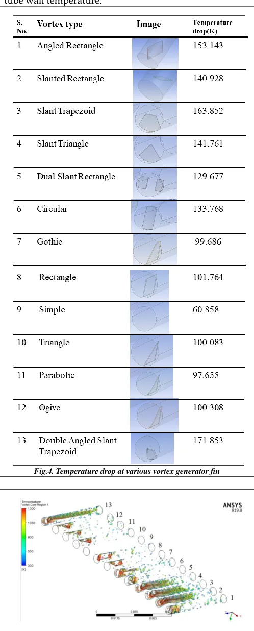
4.2 Choice of vortex generator fin
For selecting the adequate vortex fin, CFD simulation is performed over 12 different types of vortex fin and thus the fin with the maximum temperature drop is selected.
Fig.3. Different views of vortex generator fin K
LMTD 407.87 ln
2 1
2
1
LMTD A U Q
W T
C m
Q g pg
. .
47 . 2185
mm k
n d D
n t
b 42.33
1
1
1
381 IJSTR©2019
For Analysis the gas at 1000 K at inlet and 300K is taken as tube wall temperature.
Fig.4. Temperature drop at various vortex generator fin
Fig.5 Temperature at vortex core region for respective geometries
Fig. 6 Temperature contours in the various vortex finned tube
Fig.7 Temperature drop comparison for vortex finned tube
Thus from the CFD Result, we selected a double angled slanted trapezoidal vortex fin-type tube, which gives a maximum of 171.853 K of temperature drop.
4.3 Vortex Generator fin in plain tube
382
Fig.8 Different views of Plain tube with vortex fin generator
5
M
ETHODOLOGYThe basic process followed in performing CFD Simulation is [14]
• Model development
• Pre-Processing
• Meshing
• CFD Solver and Solution
• Post-processing
Fig.9. Flow chart of process of CFD Simulation followed for EGR
5.1 Model Development
In this process, the three-dimensional models of EGR Cooler are made using the Computer-Aided Design software. For this, for each analysis, the model is constructed by assembling parts of the EGR model which are tube geometry, coolant domain, and exhaust gas domain. The CAD model is prepared using the Creo Parametric software.
Fig.10. 3-D Models of geometries made using CAD software
5.1 Pre Processing
In the preprocessing process, the model is imported to the ANSYS Design modeler and the EGR model is assembled and Boolean operation is applied to define the geometry correctly. Further, the inlet and outlet are named and interface surfaces are defined.
5.2 Meshing
In meshing the model geometry is divided into a number of elements and nodes thus model discretization takes place in meshing. In this particular problem, the fine meshing setup is used.
Fig.11 Meshing on the 3-D model of EGR
5.3 Solver & Solution
The Fluent solver is used for solving heat transfer in EGR cooler geometry. In fluent solver model, physics and boundary conditions are defined provided by the properties of fluids and tube material. The pressure-based type absolute velocity formulation with steady time analysis is performed. The standard k-epsilon model with enhanced near-wall treatment is used. The following solution is processed on 3000 iterations.
5.5 Post Processing
In Post-processing, the simulation results are obtained as a result of CFD simulation based on the physics, solver, model and geometry conditions.
6
CFD
S
IMULATION383 IJSTR©2019
Fig.12. Boundary condition on EGR geometry for CFD analysis.
TABLE4
PROPERTIES OF FLUIDS IN EGR
J = Joule, K = Kelvin, m = meter, A = ampere, J = joule, kg = kilogram
7
C
ALCULATIONS7.1 Effectiveness of heat exchanger
The effectiveness of a Heat Exchanger is given by the ratio of the Actual Heat transfer to the maximum possible heat transfer can take place between that given temperature difference. [13] fer heat trans possible Maximum fer Heat trans Actual ess Effectiven
Analytical calculation of the effectiveness of Plain tube geometry type EGR
We have ρ,Density of gas = 0.348 kg /m3 ; v,Velocity of gas in tube = 25.3075 m/s ; Lc= Diameter of pipe =7.5 mm
Reynold‟s Number
Prandtl's Number
Nusselt Number
Nu = 0.24 × Re0.8 ×Pr0.4 = 74.2091
Heat transfer coefficient
Taking ho= 200 W/m2
U
i=
186.877 W/m
2Number of transfer units
776 . 0 m in C UA NTU
Heat capacity ratio
139 . 0
m ax m in
C C R
Effectiveness in terms of NTU and R for counter flow type Heat Exchanger is expressed as
Effectiveness of heat exchanger based on computational analysis
Comparing Analytical analysis with computational analysis
The above error percentage signifies the accuracy of CFD simulation analysis, it's model physics and solver used. Similar calculations are done at 10% and 30% EGR rate for both of the geometries.
EGR rate (%) Inlet Velocity(m/s)
10 5.003672
20 10.00734
30 15.01102
84 . 1557
Re
vLc
6981 . 0
Pr
384
7.2 Maximum In-cylinder temperature calculation
Fig.13 Energy balance for inlet mass flow
maTaCa + mbTbCb = mc Cc Tc
Taking ma as part of mass entered the engine cylinder after
passing through EGR cooler. Also, Ta and Ca represent the
temperature and the Specific heat of the cooled exhaust gas. mb as part of the mass of fresh air entered the engine
cylinder. Also, Tb and Cb represent the temperature and the
Specific heat of the fresh air mc as the mass of mixer of EGR
cooled exhaust gas and fresh air which is entering the engine cylinder after passing through EGR cooler. Also, Tc
and Cc represent the temperature and the Specific heat of
the gas.
Fig.14.Standard Diesel engine cycle
The final temperature at the inlet of the engine cylinder be
T
c0.2 × 623.567 × 1141 + 0.8×318×1006.08 = 1×Tc×1018
Tc = 391.20 K
T’1 = 391.20 K
T’2 = 3.156 × T’1=1234.78 K
T’3 = 2.21 × T’2 = 2728.87 K
Total heat supplied when EGR is not used is
Q = m × Cp × (T2 T3)
= . 25 × 1 18 × 2218.24 1 3.73 Q= 30909.28 W
Heat absorbed by EGR gas which is getting mixed with Inlet air
Qabsorbed=mEGR×Cp× T’2 T’3)
= (0.2×0.025)×1141×1493.91 =8671.41 W
Net Heat in Cylinder
Qnet = Absorbed = 22238.14 W
Hence the maximum temperature in cylinder is
Qnet =(0.8×0.025)×1018×(Tmax T’2)
22386.54 = (0.8×0.25)×1018×(Tmax 1234.64
Tmax= 2192.73 K
7.3 NOx Prediction
In this calculation, the amount by which the EGR will reduce NOx emissions is predicted. Only already present engine base data like air fuel ratio are used in this technique and predict what the reduction in NOx will be for different rates of EGR flow.[12]
Where
Cmix =mixing factor dependent on speed and load ;but not
on intake condition
EI NOx = Index of Emission, NOx in grams/kg of fuel Tf = Flame temperature (Max. temperature)
Fig.15 Cmix vs. % EGR flow rate [12]
For the given case of EGR with a plain tube geometry where 20% EGR rate is used is calculated for its emission index. From the calculation we have the maximum in-cylinder temperature for the same case is 2192.73 K. Therefore we have calculation as
EI NOx = 2.163 X 10⁻⁸g/kg of fuel
8
R
ESULTS ANDD
ISCUSSIONResults are obtained from the CFD Analysis simulation and further calculation is applied to get the comparison result among the geometries.
f
mix T
C NOx
385 IJSTR©2019
8.1 Temperature and Effectiveness
TABLE5
BOUNDARY CONDITION TEMPERATURE FOR PLAIN TUBE
K = Kelvin
TABLE6
BOUNDARY CONDITION TEMPERATURE FOR VORTEX TUBE
K = Kelvin
8.2 Temperature Contour
Fig.16. Comparison of temperature contours between Plain tube (Left) and Vortex generator (Right) fin tube at 10%, 20% and 30%
respectively from top to bottom
8.3 Temperature along tube length
Fig.17. Comparison of temperature along tube length for Plain tube (Left) and Vortex generator (Right) fin tube at 10%, 20% and 30%
respectively from top to bottom
8.4 Maximum In-cylinder temperature
TABLE7
MAXIMUM IN-CYLINDER TEMPERATURE FOR BOTH GEOMETRIES AT
VARIOUS EGR RATE
386
Fig.18.Maximum In-cylinder temperature while using Plain tube geometry (Black) and Vortex generator fin tube geometry (Red)
8.5 NOx Prediction
TABLE8
NOX PREDICTION FOR BOTH GEOMETRIES AT VARIOUS EGR RATE
g/kg = gram per kilogram of fuel
Fig.18. Predicted NOx while using Plain tube geometry (Black) and Vortex generator fin tube geometry (Red)
9 C
ONCLUSIONBased on the CFD simulation and the calculation it is evident that applying the vortex fin in the tube surely increases its heat transfer performance and particularly for double angled trapezoidal fin tube, the heat transfer is maximum among the used vortex generator fin tube designs. From calculation of NOx prediction for EGR geometries discussed, it is obvious that NOx emission will be less for Vortex generator fin in tube geometry when compared with plain tube geometry for EGR cooler if used in diesel engine.
R
EFERENCE[1] John B. Haywood. IC Engine Fundamentals. McGraw Hill publications (2011).
[2] Young-Ho seo, Hyung- Min Lee, Sang-Kwang Jeon, Tae-Wan ku, Beon-Soo Kang & Jeong Kim, “Homogenization of Dimpled tube and its application to structural integrity evaluation for a Dimpled-type EGR cooler using FEM”, International Journal of precision engineering and manufacturing
[3] Ibrahim Hussain Shah, Bajrang Singh Kushwaha “Modeling and simulation of EGR cooler with different types of finned tube for diesel engine”, Journal of Emerging Technologies and Innovative Research (JETIR), ISSN: 2349-5162 Volume-5, Issue 7, pp 108-116, July-2018 [4] Ibrahim Hussain Shah, Avinash Kumar Namdeo
“Thermal analysis of baffled shell and tube type EGR cooler for different types of tubes using CFD”, International Journal Of Engineering Sciences & Research Technology(2014)
[5] Ibrahim Hussain Shah, Bhupendra Singh, “A Review Study on Exhaust Gas Recirculation (EGR) Cooler Design and Using CFD to Enhance Its Performance”IJSRD - Vol. 3, Issue 04, ISSN (online): 2321-0613, pp 485-489 (2015). [6] Ibrahim H. Shah, Pawan Detwal, “Performance Study of
EGR Cooler with Different Geometries & Comparison with Dimpled-Tube Type EGR Cooler using CFD”. IJSRD, Vol. 4 ISSN (online): 2321-0613, Issue 05, pp 277-282 (2016) [7] Saurabh Kumar and Sourav Kumar, “Performance Analysis of EGR Cooler for Different Types of Finned Tubes using CFD ”International Journal of Engineering Research & Technology (IJERT) Vol. 5 Issue 06, ISSN: 2278-0181, pp 447-451 (2016)
[8] Ibrahim H. Shah, Raghvendra S. Bhadoriya, „CFD Simulation of Stack Type EGR Cooler for CI Engine‟ IJSRD, Vol. 4, | ISSN (online): 2321-0613, Issue 05, pp 332-334 (2016).
[9] Harilal S. Sorathia, Dr Pravin P. Rahhod and Arvind S. Sorathiya, “Effect of exhaust gas recirculation (EGR) on NOx emission from C.I. engine”. IJAERS[2012]
[10]Zheng, M., Reader, G. T., & Hawley, J. (2004). „Diesel engine exhaust gas recirculation––a review on advanced and novel concepts‟. Energy Conversion and Management,45(6), 883-900. doi:10.1016/s0196-8904(03)00194-8
[11]Mitsuru, I., Honda, I., & Hara, J. (2014). „Development of Vortex Generator For EGR‟ Co. Calsonic Kansei Technical Review.
387 IJSTR©2019
studies “Prediction of NOx reduction with Exhaust Gas Recirculation using the Flame Temperature Correlation Technique”. ECKAME-2006-T-23, March 18–19, pp 378-385 (2006),
[13]Holman, J. (2014). Heat transfer. Boston: McGraw-Hill [14]ANSYS ®,„Analysis Fluent Tutorial Guide‟, Release