SMALL PROXIMITY COUPLED CERAMIC PATCH ANTENNA FOR UHF RFID TAG MOUNTABLE ON METALLIC OBJECTS
J.-S. Kim, W.-K. Choi, and G.-Y. Choi
RFID/USN Research Group
Electronics and Telecommunications Research Institute (ETRI) 161 Gajeong-dong, Yuseong-gu, Daejon, 305-700, Korea
Abstract—A very small patch type RFID tag antenna (UHF band) using ceramic material and proximity coupled feeding structure mountable on metallic objects is presented. The proposed tag size is 25×25×3 mm. Both of the radiating part and the feeding part of the proposed antenna is located in the same plate for easy implementation. The resistive and reactive components of the input impedance of the antenna can be easily matched to the tag chip impedance from the size of the feed loop and the distance between feed loop and radiating patch. The antenna satisfactorily operates on metal plates, so it is applicable in many applications. The proposed design is verified by simulation and measurements which show good agreement.
1. INTRODUCTION
in passive RFID tag chips. So, the impedance matching technique using inductive coupling has been studied in relation to RFID tag antennas [2, 3]. The folded dipole or meandered dipole antennas with inductive coupling mechanism are widely used in many applications since they can be printed on a very thin film. However, in special RFID applications such as metallic components, the general label tags cannot operate in the surface of the conducting materials because of the degradation of tag antennas. Proper antenna design for RFID tag applications is becoming essential for the maximization of RFID system performance. In many applications, RFID tags need to be placed on metallic materials and to be very small. To meet this application requirement, the planar inverted-F antenna (PIFA) which can be used on metal has been proposed as a tag antenna [4]. To reduce the size of the patch antenna, two symmetric shorted microstrip patch antennas and a feed loop is studied [5]. To expand the bandwidth of the metal tag antenna, there have been studies which proposed using orthogonal proximity coupled patch antennas [6], and using T-matching network and double symmetrical radiating patches shorted to ground plane [7] in RFID tags.
Most of the metal tags consist of the complex geometry of more than two layers and they need to be implemented very carefully. Metal tags applied in specification fields have to be manufactured to a smaller size than the existing metal tags. In this paper we discuss a very small tag antenna, which uses a ceramic material, an inductively coupled feed and patch antenna suitable for the UHF band RFID tag which can be placed on the conducting materials and can be used in specified applications. Both of the feeding part and radiating part is located in the same plate, so the implementation process is very simple and then the cost can get lower. A rectangular tag with a height of 3 mm and an area of 25×25 mm is proposed.
2. EQUIVALENT CIRCUIT OF THE TAG ANTENNA
Top view
Side view 25
25
3
Via hole
Unit : mm
Z Y
X
X
Tag chip Feed loop
Radiating body
Horizontal Slits
(a) The geometry of the proposed antenna
(b) The photograph of the fabricated tag
C
rR
rL
rL
loopZ
aM
equivalent circuit of
the radiating body
equivalent circuit of
the feed loop
Figure 2. Equivalent circuit of the proposed antenna.
of the antennaZa is given by:
Za=Ra+jXa=Zloop+
(2πf M)2 Zr
(1)
whereZrandZloopare the individual impedances of the radiating body and the feed loop, respectively, M is the mutual inductance between them and f is the operating frequency.
Near the resonant frequency fo of the radiating body, the resistance and reactance components ofZa are given by [3]:
Ra =
(2πf M)2 Rr
1
1 +u2 (2a)
Xa = 2πf Lloop−
(2πf M)2 Rr
u
1 +u2 (2b)
where u = Qr(f /fo − fo/f) and Qr is the quality factor. When the operating frequency f equals to the resonant frequency fo the components of the impedance becomes:
Ra(f =fo) =
(2πfoM)2 Rr, fo
(3a)
Xa(f =fo) = 2πfoLloop (3b)
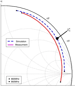
+j
+j2
+j4
860MHz 960MHz
Z*C
Simulation Measurment
Figure 3. The input impedance characteristics.
3. TAG ANTENNA DESIGN
of the tag chip is found to be in the range of 3 to 150 Ω, and the reactance is in the range of−200 to−50 Ω (capacitive). In this paper, the antenna is designed for a tag chip (commercial RFID tag chip: Alien Higgs chip) with an input impedance of Zc = (12−j140) Ω at a resonant frequency of 910 MHz. The conjugate match is achieved between the input impedance of the proposed antenna and the tag chip by adjusting radiating patch and the feed line. By varying the distance between the radiating patch and the feed line, the resistive component of the input impedance can be adjusted and the reactive component of the input impedance can be adjusted by varying the length of the feed loop. The operating frequency is slightly adjusted by varying the horizontal slit length of the radiating patch, while the input impedance of the antenna is almost unaffected.
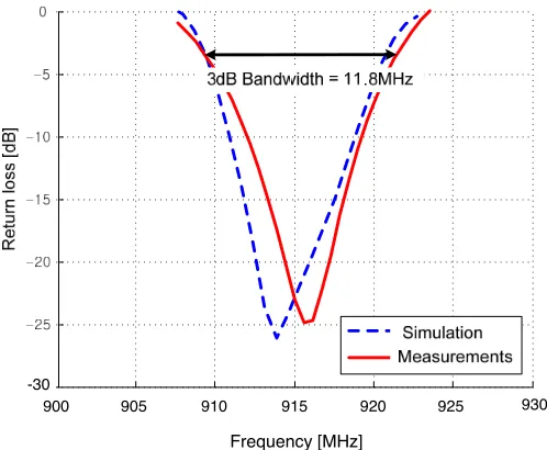
-30
900 905 910 915 920 925 930
Frequency [MHz]
Figure 4. The return loss of the proposed antenna.
4. SIMULATION AND MEASUREMENT
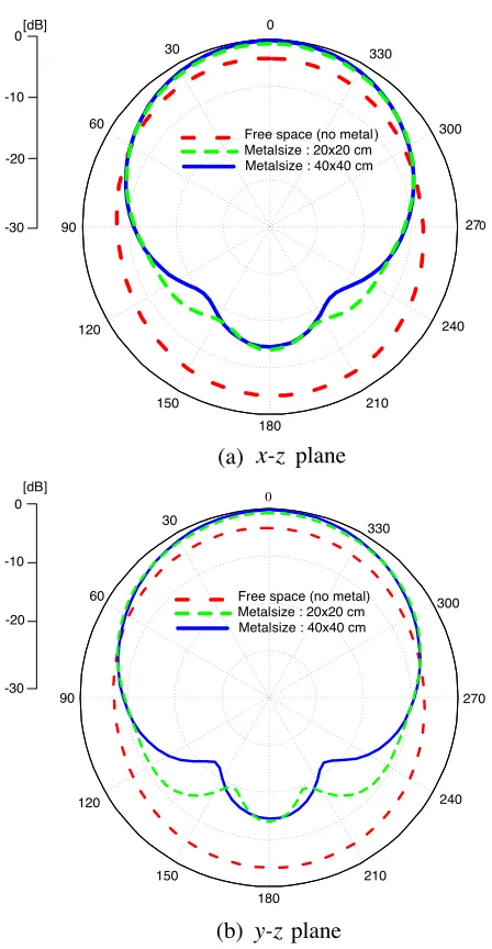
-30 -20 -10
0[dB]
Free space (no metal ) Metalsize : 20x20 cm Metalsize : 40x40 cm
120 330 300 210 180 270 240 150 0 30 60 90
(a) x-z plane
Free space (no metal) Metalsize : 20x20 cm Metalsize : 40x40 cm
120 330 300 210 180 270 240 150 -30 -20 -10 0 [dB] 0 30 60 90
(b) y-zplane
Figure 5. Calculated radiation pattern by CST microwave studio at 910 MHz.
data agreed well with the simulated data.
Figure 4 shows the simulated and measured return loss of the proposed antenna with respect to the conjugate of the input impedance of the tag chip Zc∗ when it is attached to a metal plate. The 3 dB return loss bandwidth is 11.8 MHz which fully covers the bandwidth of the Korean RFID frequency band (908.5∼914 MHz).
To study the effect of the size of metallic objects for the prototype antenna, the radiation pattern is simulated with different size of metal plates (mounted on free space, 20×20 cm, 40×40 cm) in Figure 5. Figure 5 shows that the main beam direction is not steered by the metallic plates, and the proposed antenna has an omni-directional radiation pattern. The half power beamwidths are about 100◦ in both
E-and H-planes. The simulated directivity of proposed antenna with metal plate is about 5.21 dBi and the simulated radiation efficiency is about 35% at resonant frequency of 910 MHz because of the small antenna size and high dielectric constant of the substrate.
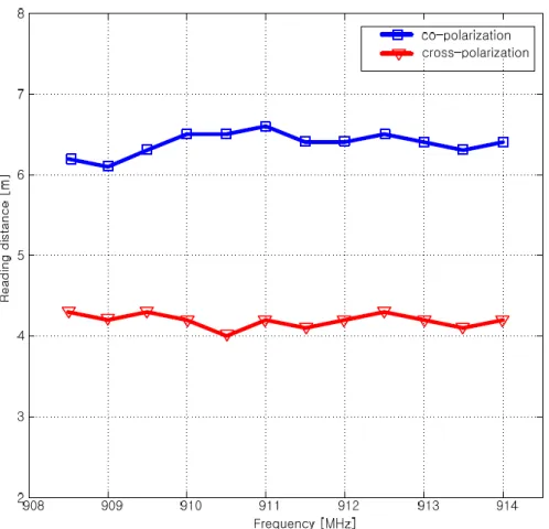
Figure 6. Maximum reading distances of tag mounted on metal plate via Korean RFID frequency.
(EPR-630) which authenticated in the EPC global and the patch type reader antenna with linear polarization. The measurement was carried out with the antenna placed at the center of a 40×40 cm metal plate. The reading distance is over 6 m for all frequencies in Korean RFID band, so it shows that the bandwidth of this proposed antenna fully covers the Korean RFID band.
Table 1 shows the maximum reading distances of tag for metal plates of different sizes. It is clear that the antenna operates satisfactorily on various size of metal plates, so the tag can be used on metal plates for the best performance in specific applications such as automobile components.
Table 1. Measured maximum reading distances of tag mounted on various sizes of metal plate.
Metal plate size Maximum reading distance [m] Free space (no metal ) 4.2
20×20 cm 6.4
40×40 cm 6.6
5. CONCLUSIONS
A design for very small tag antenna (25×25×3 mm) using ceramic material at UHF band mountable on metallic objects was implemented. The antenna can be directly matched to the arbitrary complex impedance of a tag chip. It is verified that the proposed tag has good performance by measuring the reading distance over 6 m on metallic plates. The proposed tag is very small, so it may be used with a conducting plate to facilitate mounting it on curved surfaces as cans if necessary.
ACKNOWLEDGMENT
REFERENCES
1. Seshagirl Rao, K. V., P. V. Nikitin, and S. F. Lam, “Antenna design for UHF RFID tags: A review and a practical application,”
IEEE Trans. Antennas Propagat., Vol. 53, No. 12, 3870–3876, Dec. 2005.
2. Choo, H. and H. Ling, “Design of electrically small planar antennas using inductively coupled feed,”Electron. Lett., Vol. 39, No. 22, 1563–1565, Oct. 2003.
3. Son, H. W. and C. S. Pyo, “Design of RFID tag antennas using an inductively coupled feed,” Electron. Lett., Vol. 41, 994–996, Sep. 2005.
4. Choi, W., H. W. Son, J. Bae, G. Y. Choi, C. S. Pyo, and J. Chae, “An RFID tag using a planar inverted-F antenna capable of being stuck to metallic objects,”ETRI J., Vol. 28, No. 2, 216–218, Apr. 2006.
5. Yu, B., S.-J. Kim, B. Jung, F. J. Harackiewicz, and B. Lee, “RFID tag antenna using two-shorted microstrip patches mountable on metallic objects,” Microwave and Optical Technology Letter, Vol. 49, No. 2, 414–416, Feb. 2007.
6. Son, H.-W. and G.-Y. Choi, “Orthogonally proximity-coupled patch antenna for a passive RFID tag on metallic surfaces,”
Microwave and Optical Technology Letter, Vol. 49, No. 3, 715– 717, Mar. 2007.