WC-281 Circular Waveguide Terminator Essential in Microwave
Plasma Interaction Experiments for SYMPLE
Jitendra Kumar1, *, Raj Singh2, and V. P. Anitha2
Abstract—This work presents the novel design and development of a WC-281 circular waveguide terminator or termination for microwave plasma interaction experiments. Final waveguide terminator is designed by using the quad wedge of FR4, cone of resistive material, i.e., Kanthal and Teflon discs. Kanthal is a composition of aluminium, chromium, and iron. Wedge shape geometry helps in gradually changing the impedance and thus decreasing the return loss, while resistive material Kanthal attenuates the field before reaching the receiving end. This makes it suitable for use as the finest microwave termination. The final model of terminator decreases the reflection coefficient (S11) up to−40 dB while
reduces the transmission coefficient (S21) immensely up to −63 dB at 2.85 GHz.
1. INTRODUCTION
SYstem for MicrowavePLasma Experiments (SYMPLE) is an experimental system to investigate the physics of linear and nonlinear interaction of high-power microwave (HPM) with plasma in Institute for Plasma Research (IPR), Gandhinagar, India [1]. The experimental system is conceived to investigate the physics of interaction of extremely intense electromagnetic waves (ωp > ωem). The supposed study
has relevance in understanding laser-plasma interactions applicable in inertial fusion [2]. Impedance mismatches in a radio-frequency (RF) electrical transmission line cause power loss and reflected energy. In an RF transmission system, the reflection of power from the receiving end in a system decreases the efficiency of the system. Sometimes it may even cause damage to the generator attached at the sending end. Matched loads or terminations are designed to absorb incident energy without appreciable reflection. Matched termination is the most required part of the passive waveguide components like directional couplers and filters [3]. Coaxial terminations and waveguide terminations are collectively known as RF terminations or microwave terminations. They are used to absorb energy and prevent a signal from reflecting back from mismatch ports. The design and development of the matched terminations for a rectangular waveguide operation on fundamental mode are well established [4, 5]. However, circular waveguide terminations are not available conventionally, and some concepts related to circular waveguide termination are given in [6]. Hence, R&D efforts are required to have the termination with the circular waveguide.
Present work provides the design, development, and simulated results of termination along with a systematic approach based on a circular geometry. Microwave termination is generally used in networking equipment, optical transmission device, network analyzer, bit error ratio testing system (BERTS), fixed wireless access (FWA), and for measurement purposes in other applications like S -parameters of waveguides, directional couplers, and filters. Here, a matched terminator is designed for WC-281 circular waveguide. Terminations should have features like high performance, full assortment of impedance matching, low voltage standing wave ratio (VSWR), and usability over wide bandwidth.
Received 29 March 2019, Accepted 12 June 2019, Scheduled 25 June 2019
* Corresponding author: Jitendra Kumar ([email protected]).
86 Kumar, Singh, and Anitha
2. MATCHING NETWORK
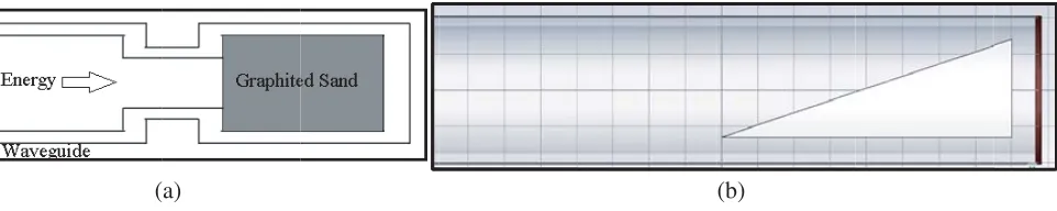
Electromagnetic energy is often passed through a waveguide to transfer the energy. A waveguide may be terminated in a resistive load that is matched to the wave impedance of the waveguide otherwise without proper impedance matching, and standing waves cause a large decrease in the efficiency of the waveguide [7]. The resistive load is most often called a dummy load because its only purpose is to absorb all the energy in a waveguide without causing standing waves. There is no place on a waveguide to connect a fixed termination resistor; therefore, several special arrangements are used to terminate waveguides [4, 5, 8–10]. One method is to fill the end of the waveguide with a graphite and sand mixture, as illustrated in Fig. 1(a). When the fields enter the mixture, they induce a current flow in the mixture which dissipates the energy as heat. Another method for terminating a waveguide is the use of a wedge of highly resistive material, as shown in of Fig. 1(b). The plane of the wedge is placed perpendicular to the magnetic lines of force. When the magnetic field lines cut through the wedge, current flows in the wedge and causes a power loss. As with the other methods, this loss is in the form of heat, since very little energy reaches the end of the waveguide, and reflections are minimum.
(a) (b)
Figure 1. Matched Termination: (a) Graphited sand based, (b) wedge of highly resistive material based.
3. DESIGN AND ANALYSIS
Matched termination depends on the type of waveguide, frequency range, and also type of feed for TE or TM mode. This report deals mainly with TE mode. The matched termination works on the principle of attenuating the microwaves. The attenuation depends on whether absorbing material is placed parallel to the electric field lines in the case of loss on relative permittivity, or it is placed parallel to the magnetic field lines for the case of loss on the basis of relative permeability of the material.
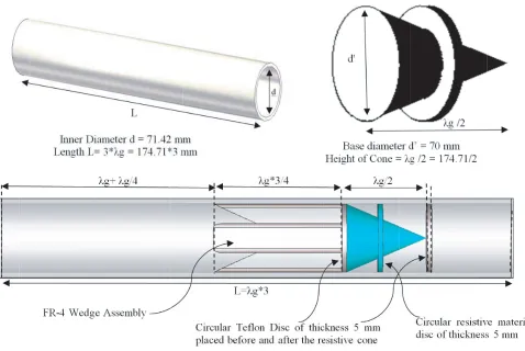
WC-281 circular waveguide of aluminium is used for investigation. The inner diameter of WC-281 circular waveguide is 71.42 mm, and the length is multiple of guided wavelength (λg). The operating range of WC-281 is between 2.82 and 3.88 GHz. Here, the operating frequency is considered nearly 3 GHz for all calculations. The calculated cutoff frequency (fc =c/λc) for TE11 mode comes out to be
2.46 GHz, and the guided wavelength (λg) is 174.71 mm. To terminate the waves, different shapes of the wedge with a length nearly 3λg/4 are used in the circular waveguide. Wedges are made up of FR-4 (epoxy resin) dielectric material having permittivity (εr) 4.3 with dissipation factor (tanδ) 0.025. A resistive cone is to be placed after the FR-4 wedge to minimize the energy (almost nil) at receiving port. The cone is made of Kanthal (a composition of aluminium, chromium, and iron) which is a resistive material. To further increase the absorption and refine the results, circular discs of Teflon of thickness 5 mm are placed before and after the resistive cone. The final specification of the proposed model of terminator for WC-281 circular waveguide is shown in Fig. 2. The long edges of the FR-4 wedge are blended so as to get fit inside the circular waveguide.
Figure 2. Specification of the proposed model of termination.
(a)
(d)
(b) (c)
(e)
Figure 3. Development steps of the termination assembly inside the circular waveguide: (a) Slab, (b) wedge, (c) quad wedge, (d) quad wedge with cone, (e) quad wedge with cone & discs.
(almost nil) at receiving port as shown in Fig. 3(d). Finally, 2 discs of Teflon and a resistive disc are placed to increase the absorption and refine the results as shown in Fig. 3(e).
4. EXPERIMENTAL RESULTS AND DISCUSSIONS
88 Kumar, Singh, and Anitha
of terminator are carried out using the CST Microwave Studio [11], full-wave electromagnetic (EM) simulation software.
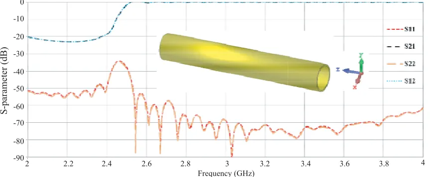
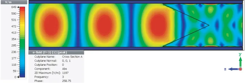
Figure 4 shows the variation of S-parameter versus frequency for WC-281 circular waveguide. It is observed that the simulated cutoff frequency is nearly 2.5 GHz, and after the cutoff, there is very good transmission without any reflection. To analyse the propagation of Electric field (E-field), a field-monitoring tool is used. The E-field propagation of EM wave in the circular waveguide at 3 GHz is shown in Fig. 5. It is clearly perceived that wave is completely propagated from the first end to the last end of the waveguide without any disturbance.
0
-10
-20
-30
-40
-50
-60
-70
-80
-90
2 2.2 2.4 2.6 2.8 3 3.2 3.4 3.6 3.8 4
Frequency (GHz)
S-parameter (dB)
Figure 4. S-parameters versus frequency for WC-281 circular waveguide.
Figure 5. Propagation of EM wave in the circular waveguide at 3 GHz.
Then, a slab of FR-4 dielectric (epoxy resin) is placed along the axis to terminate the waves as well as prevent the reflection. It is easily depicted fromS-parameters plot that this slab reduces the reflection coefficient (S11) to about−9 dB only and absorption (S21) to about−64 dB before the receiving port at
frequency 2.95 GHz as shown in Fig. 6. It means that nearly 10% power is reflected back at the input end of the terminator. Fig. 7 shows the E-field propagation of EM wave in the circular waveguide for slab assembly of terminator at 2.95 GHz which also verifies the less termination at slab structure.
Further, to improve the return loss, a wedge structure by changing the slab shape of terminator is used. These structures help in reducing the reflection as shown in Fig. 8. It is observed that wedge structure reduces the reflection to about−22 dB at frequency 3 GHz with maintaining good absorption (S21=−64 dB) before the receiving port. Hence, the reflection level is improved with respect to the last
design. The E-field propagation of EM wave in the circular waveguide for wedge structure of terminator at 3 GHz is shown in Fig. 9 which also verifies the less termination of EM wave at wedge structure.
0
-10
-20
-30
-40
-50
-60
-70
-80
2.5 2.7 2.9 3.1 3.3 3.5
Frequency (GHz)
S-parameter (dB)
Figure 6. S-parameters versus frequency for slab assembly of terminator.
Figure 7. Propagation of EM wave in the circular waveguide for slab assembly of terminator at 2.95 GHz.
0
-10
-20
-30
-40
-50
-60
-70
-80
2.5 2.7 2.9 3.1 3.3 3.5
Frequency (GHz)
S-parameter (dB)
90 Kumar, Singh, and Anitha
Figure 9. Propagation of EM wave in the circular waveguide for wedge structure of terminator at 3 GHz.
0
-10
-20
-30
-40
-50
-60
-70
-80
2.5 2.7 2.9 3.1 3.3 3.5
Frequency (GHz)
S-parameter (dB)
Figure 10. S-parameters versus frequency for quad wedge of terminator.
Figure 11. Propagation of EM wave in the circular waveguide for quad wedge of terminator at 3 GHz.
circular waveguide. The comparable results are achieved at 3 GHz with less termination of the wave at wedge as shown in Figs. 10 and 11.
0
-10
-20
-30
-40
-50
-60
-70
-80
2.5 2.7 2.9 3.1 3.3 3.5
Frequency (GHz)
S-parameter (dB)
Figure 12. S-parameters versus frequency for quad wedge with cone of terminator.
Figure 13. E-field propagation in circular waveguide for terminator with quad wedged and cone at 2.85 GHz.
frequency for the same waveguide terminator. Fig. 12 shows the variation of reflection (S11) and
transmission (S21) versus frequency. The resonance forS11is obtained at 2.85 GHz with a bandwidth of
∼130 MHz forS11<−20 dB ranging from 2.80 to 2.93 GHz with satisfactory absorption. This can also
be verified from Fig. 13 which shows the E-field propagation of EM wave in the circular waveguide for quad wedged with a cone. There is almost perfect absorption at terminator assembly, i.e., quad wedge with cone.
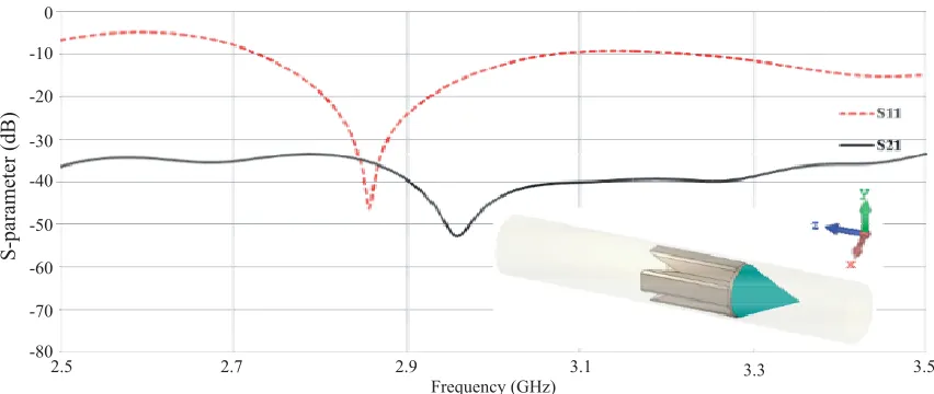
To further refine the results, circular discs of FR4 and Teflon with thickness of 5 mm are placed before and after the resistive cone. Teflon discs decrease the reflection coefficient (S11) to about−42 dB,
and the transmission coefficient (S21) parameter is also immensely reduced nearly below −62 dB at
2.85 GHz as clearly shown in Fig. 14. The final model of terminator also achieves the bandwidth of ∼130 MHz for S11 <−20 dB ranging from 2.80 GHz to 2.93 GHz. The proposed model of terminator
decreases the reflection coefficient (S11) up to −40 dB while reduces the transmission coefficient (S21)
immensely up to −63 dB at 2.85 GHz. The S-parameter for the geometry indicates that purpose for absorption of energy such that it must not reach at receiving port is met. It also satisfies the reflection level. It is perceived from S21 parameter that energy is absorbed in the cone itself.
92 Kumar, Singh, and Anitha
0
-10
-20
-30
-40
-50
-60
-70
-80
2.5 2.7 2.9 3.1 3.3 3.5
Frequency (GHz)
S-parameter (dB)
Figure 14. S-parameters versus frequency for quad wedge with cone and discs of terminator.
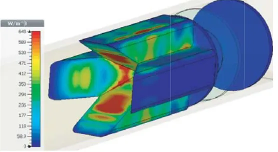
Figure 15. E-field propagation in circular waveguide for terminator with quad wedged, cone and Teflon discs.
Figure 16. Power loss density in circular waveguide for terminator with quad wedged, cone and Teflon discs.
frequency of 2.85 GHz, and result is shown in Fig. 16. The power loss density value is expressed in units of watts per cubic meter (W/m3). Table 1 compares the achieved outcome for step-by-step improvement of the proposed termination.
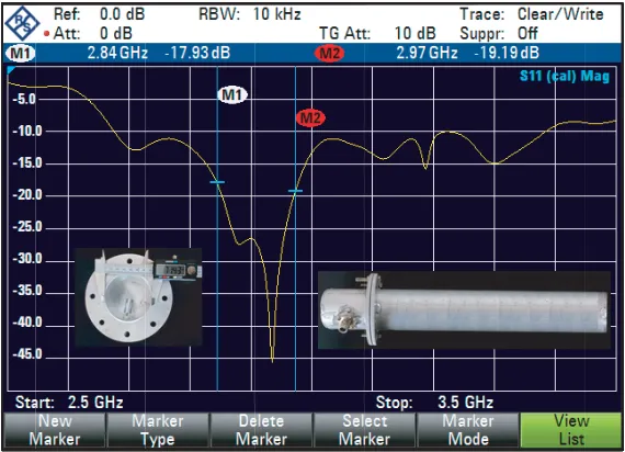
Figure 17. Measured reflection coefficient for proposed terminator.
Table 1. Comparison of the proposed structures.
Shape fr (GHz) BW (MHz) S11 (dB) S21 (dB) P (%)
Slab 2.95 0 −9.2 −64.1 12
Wedge 3 ∼80 −21.6 −63.6 0.7
Quad-wedge 3 0 −16.3 −48.7 2.3
Quad-wedge with cone 2.85 ∼130 −38.4 −34.9 0
Quad-wedge with cone & discs 2.85 ∼130 −37.6 −61.5 0
fr — Resonant frequency, BW — Bandwidth for S11<−20 dB,P — Reflected Power
in Fig. 17. The fabricated model of circular waveguide terminator and the used connector is shown in inset view. Commercially available N-type connector with a special structure of inner pin is used for the measurement of S-parameter (S11). Due to unavailability of Kanthal material, an equivalent
resistive material is used. The measured result achieves the bandwidth of∼120 MHz for S11<−20 dB
ranging from ∼ 2.85 GHz to ∼ 2.97 GHz. Table 2 compares the simulated and experimental results which are in decent agreement. However, the minor differences in simulated and measured results are mainly due to the fabrication inconsistencies and imperfections while drilling and welding. Thus, the proposed terminator can also be a suitable candidate for such an application where high performance and low VSWR are required.
Table 2. Comparison between simulated and measured results.
Parameters fr (GHz) BW (MHz) S11 (dB) BW Range
Simulated 2.85 ∼130 −38 2.80–2.93
Measured 2.93 ∼120 −44 2.85–2.97
94 Kumar, Singh, and Anitha
5. CONCLUSION
The waveguide termination based on resistive material for a WC-281 circular waveguide is successfully analysed, and results are discussed. The wedge shape geometry helps in gradually changing the impedance and thus decreasing the reflection S11. To terminate the propagation, a resistive material
Kanthal modeled in a conical shape is placed facing its tip to the receiving end and attenuates the field before reaching the receiving end. This makes the terminator suitable for practical use. The position and geometry of the structure being used to decide the parameters for return loss and attenuation. Through the existing literature, it is claimed that such a geometry has not been explored so far for a circular waveguide termination. Further work for enhancing the bandwidth is in process.
REFERENCES
1. Anitha, V. P., P. J. Rathod, R. Singh, and D. V. Giri, “Developmental aspects of microwave-plasma interaction experiments: Phase-1,”IEEE Transactions on Plasma Science, Vol. 44, No. 10, 2226–2231, 2016.
2. Anitha, V. P., A. Das, Y. C. Saxena, A. Shyam, and P. K. Kaw, “Interaction of high power microwave with plasma,” IEEE International Vacuum Electronics Conference (IVEC), 481–482, 2011.
3. Yoneyama, T. and S. Nishida, “Nonradiative dielectric waveguide,”Infrared and Millimeter Waves, Vol. 11, 61–98, 1984.
4. Teodoridis, V., T. Sphicopoulos, and F. E. Gardiol, “The reflection from an open-ended rectangular waveguide terminated by a layered dielectric medium,” IEEE Transactions on Microwave Theory
and Techniques, Vol. 33, No. 5, 359–366, 1985.
5. Rebollar, J. M., “Response of waveguides terminated in a tapered metallic wall (short paper),”
IEEE Transactions on Microwave Theory and Techniques, Vol. 34, No. 1, 175–178, 1986.
6. Kumar, J., Zeeshan, R. Jaiswal, A. Baranwal, R. Singh, and V. P. Anitha, “Design and development of a circular waveguide terminator for microwave plasma interaction experiments,” 32nd National
Symposium on Plasma Science&Technology, Institute for Plasma Research, Gandhinagar, Gujarat,
India, Nov. 2017.
7. Pozar, D. M., Microwave Engineering, John Wiley & Sons, 2009.
8. Chhotray, S. K., M. Sumathy, K. S. Bhat, and L. Kumar, “Design of a broad band matched termination for an overmoded waveguide,.” IEEE International Vacuum Electronics Conference
(IVEC), 199–200, 2011.
9. Fusco, V. F., “Low reflection coefficient waveguide termination using an imaging method,”Twelfth
International Conference on Antennas and Propagation, (ICAP 2003), 716–719, Exeter, UK, 2003.
10. Uhm, M., H. Lee, C. Kwak, S. Yun, and I. Yom, “Compact waveguide load with thin film resistor,”
PIERS Proceedings, 1402–1405, Prague, Czech Republic, July 6–9, 2015.
![[Dicarbonyl(η5 cyclopentadienyl)iron(II)] μ2 1,3 propanediyl [dicarbonyl(η5 cyclopentadienyl)ruthenium(II)]](data:image/gif;base64,R0lGODlhAQABAIAAAP///wAAACH5BAEAAAAALAAAAAABAAEAAAICRAEAOw==)