172
Dynamic Soil Structure Interaction Effects on Modeled
Building Frame Supported by Pile foundation
Syed Jalaludeen Shah
1, Swathy K. G.
2Civil Engineering1, 2, Associate Proffesor1, P. G. Student2, Universal Engineering College, Vallivattom, Thrissur, Kerala, India1, 2
Email: [email protected], [email protected]
Abstract- Framed structures are usually analyzed with their bases considered to be either completely rigid or
hinged. However foundations resting on deformable soils undergo deformation depending on relative rigidities of foundation and soil. Even though pile performs better than shallow foundation in seismic load, non linear soil behavior and dynamic loading create a complex motion due to soil action on pile. In the current study the seismic behavior of a building frame and the supporting pile was studied by considering the non linearities and contact interface at soil pile interface. For that a 3-D finite element analysis was carried out using ANSYS software by modeling a building frame with basement wall resting on grade beam supported by pile group. A parametric study was conducted to understand the pile soil behavior by varying pile number in a group (1, 3 and 5), soil properties (soft clay and loose sand) and soil pile contact condition (smooth and bonded) under seismic load. The dynamic response of pile-structure system was studied by considering the displacement, stress and acceleration at various points. Transient dynamic analysis was done using Kobe earthquake details. It was found that pile number in a group, soil properties and contact condition significantly affects the seismic response of structure. Soil-structure interaction effect found to increase displacement in the range 78 - 98% compared to conventional method of analysis.
Index Terms- Framed structure, pile group, grade beam, non linearities, fixed base, seismic response.
1. INTRODUCTION
The impact of seismic load on pile supported structures has been a matter of concern since some greater earthquakes. Pile being a deep foundation deemed to perform well in earthquake prone areas than shallow foundation. A review on the damages due to earthquakes shows that they have disastrous impact not only on superstructure but also on structures embedded in soil. Being the most commonly adopted deep foundation; studies on the seismic response of structures supported on pile foundation are significant.
Previously the response of structures to earthquake excitation was studied by considering the foundation of a structure to be rigidly fixed to the ground. This approach makes calculations easier and delivers quick solutions. Neglecting compressibility of soil mass results in redistribution of bending moment and shear force. The actual response of a structure to earthquake excitation is highly complex and depends on interaction of superstructure, foundation and soil on which it rests. During past and recent earthquakes it was realized that soil structure interaction effect plays an important role in determining the behavior of structures. So this work is an investigation on the seismic performance of frame supported on pile foundation considering soil-pile-structure interaction. Several studies have been made on the effect of soil-structure-interaction problems from time to time in attempt to obtain more realistic analysis. In 2000 Cai et.al developed 3-dimensional nonlinear Finite
Element Analysis system to study soil structure interaction by Hiss modeling. Drawback of his work
173 time, but this method neglects the combined effect of
kinematic and inertial interaction. Instead of two dimensional analyses, three dimensional nonlinear analyses needed to simulate the actual soil structure behavior because the soil-foundation-structure goes to nonlinear state under seismicity.
In this work, non linear 3-D FEA analyses were conducted on building frame with basement wall resting on grade beam supported by pile foundation. To study the dynamic soil structure interaction by direct method, this system is subjected to seismic load. In order to study the influence of number of pile in a group, the structure was modeled with single pile, 3 piles in a group and 5 piles in a group. Studies were performed in two homogeneous soil conditions, loose sand and soft clay so as to understand the variation of pile-structure response with change in soil properties. Soil pile interface have a great impact on the seismic behavior of structure to investigate more about this the contact between pile and soil modeled in terms of interface friction.
2. NUMERICAL PROBLEM
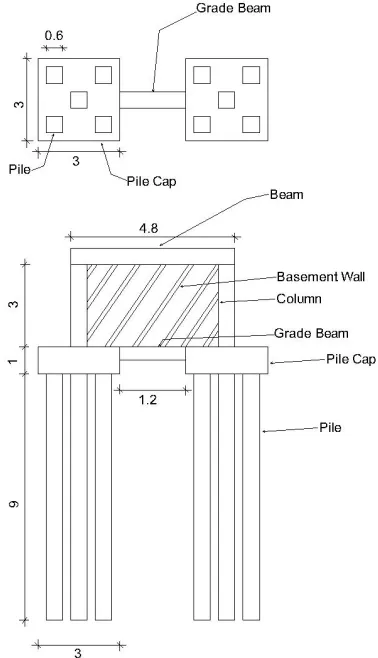
Frame with basement wall, resting on grade beam, supported by pile group is commonly seen in multistoried buildings. Here a similar structure has modeled since the earthquake performance of structures supported by piles with combined vertical and horizontal load is significant. So the structure was designed for vertical as well as lateral load due to soil pressure using IS 456-2000, IS-2911-Part 1-1979 and IS SP 16-1980. The superstructure has the same dimensions in all models. Soil dimension is taken as 3 times the pile cap size. Columns are of 3 m in length and 0.6 x 0.6 m in size. Beam is 4.8 m length and 0.3 x 0.6 m in size. Wall size is 0.3 x 2.4 m and has a height of 2.4 m. Grade beam dimension is 0.3 x 0.5 m, length is 4.2 m for single pile and 2.4 m for pile groups. Pile cap thickness is 1 m, its size for single pile is 1.2 x 1.2 m and for pile groups it is 3 x 3 m. Pile considered in this study is pure friction pile so as the number of pile in a group decreases the length of pile increases. RCC Piles are square in size with dimension 0.6 x 0.6 m. For friction piles the pile length varies with the number of piles and soil type the pile length obtained after design is shown in table 1. The dimension of the structure obtained for 5 piles in a group is shown in Fig. 1.
Table 1. Pile length for corresponding pile number
Sand Clay
1 pile
3 pile
5 pile
1 pile
3 pile
5 pile
18 m 9 m 6 m 72 m 27 m 19 m
Fig.1. Dimension of 5 piles in a group in loose sand (All dimensions in m)
3. FINITE ELEMENT MODELING
174 Fig. 2. Model of single pile in loose sand
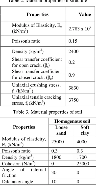
Table 2. Material properties of structure
Properties Value
Modulus of Elasticity, Ec
(kN/m2) 2.783 x 10
7
Poisson's ratio 0.15 Density (kg/m3) 2400 Shear transfer coefficient for open crack, (βt) 0.2 Shear transfer coefficient for closed crack, (βc) 0.9 Uniaxial crushing stress, fc (kN/m2 )
3830 Uniaxial tensile cracking
stress, ft (kN/m 2
) 3750
Table 3. Material properties of soil
Properties
Homogenous soil Loose
sand
Soft clay
Modulus of elasticity, Es (kN/m2)
25000 4000 Poisson's ratio 0.3 0.3 Density (kg/m3) 1800 1700 Cohesion (N/m2) 0 25000 Angle of internal
friction 30 0
Dilatancy angle 10 0
One of the major disastrous earthquakes in which pile supported frame structures undergone severe damage was 1995 Kobe earthquake at Japan. So acceleration time history of this earthquake having magnitude of 6.9 was considered for this study. Along with transient load vertical and horizontal static load was provided. Fixed boundary condition was provided at the soil bottom and movement at x and z direction was restricted at the lateral faces of soil. Since earthquake primarily acts on soil medium, the seismic load was applied on to soil at the base.
4. RESULTS AND DICUSSION
A modal analysis was primarily conducted in order to examine the possibility of resonance in soil structure system. Exciting frequency of Kobe earth quake was 4.48 Hz and the frequency obtained for soil structure system varies between 0.2117 Hz to 1.8 Hz. Hence there is no possibility for resonance. Fundamental time period obtained for fixed base analysis was 0.0414 seconds while considering soil-structure the fundamental period ranges in between 0.735-3.15 seconds. By neglecting soil structure interaction fundamental period is under estimated. While providing fixed base the foundation is assumed as rigid. In soil-foundation-structure interaction the foundation flexibility is also considered. Increased flexibility of model subjected to analysis increases the fundamental period and therefore reduces base shear. After this a transient analysis was conducted in pile supported frame with varying pile number, soil properties and interface condition. The result obtained after analysis was plotted in terms of displacement, stress and acceleration versus time plot. The displacement, stress and acceleration plot for frame supported by five piles in a group embedded in soft clay under bonded condition is as shown in Fig. 3, 4 and 6.
Fig. 3. Displacement time graph of 5 piles embedded in soft clay under bonded condition
175
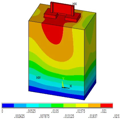
Maximum vertical displacement obtained from the above graph is 0.0253 m and the maximum stress is 8150 kN/m2. From the stress diagram the column base stress, pile head stress and pile tip stress obtained as 1820, 1040 and 40 kN/m2 respectively. Displacement contour for 5 piles in clay under bonded condition shown in Fig. 5.
Fig. 5. Displacement contour of framed structure with 5 piles in clay under bonded condition
Fig. 6. Acceleration time plot of 5 piles in clay under smooth and bonded condition
Acceleration of the system got increased in the smooth condition than bonded shown in Fig. 6. Acceleration increased about 60% for smooth condition than bonded. As in smooth condition the friction between pile and soil is zero, the sliding of pile with respect to the soil increases hence the acceleration in smooth case increases. In the case of smooth condition the frictional resistance offered between pile and soil is minimum hence more response for smooth condition.
Similarly the graph and contours of frame supported by single pile and 3 piles was plotted and
obtained results are summarized in the table 4, table 5, Table 6 and Table 7.
Table 4. Vertical displacement obtained by transient analysis
Pile group
Loose sand (m) Soft clay (m)
Smooth Bonded Smooth Bonded
1 pile 0.0335 0.0272 0.0943 0.090 3 pile 0.0125 0.0113 0.029 0.0273 5 pile 0.0105 0.0093 0.0276 0.0253
Conventional method – 0.002 m
Table 5. Stresses obtained by transient analysis for frame supported by single pile.
Stress location
Loose sand (kN/m2)
Soft clay (kN/m2) Smooth Bonded Smooth Bonded
Column
top 8090 8083 8240 8187
Column
base 2490 2370 2500 1970 Pile
head 3570 3150 3150 2400 Pile tip 2300 390 540 390
Table 6. Stresses obtained by transient analysis for frame supported by 3 piles in a group
Stress location
Loose sand (kN/m2)
Soft clay (kN/m2)
Smooth Bonded Smooth Bonded
Column
top 8090 8080 8210 8190
Column
base 1660 1610 1500 1470 Pile
head 790 700 980 890
Pile tip 190 180 26 20 Table 7. Stresses obtained by transient analysis for
176 As the pile number in a group increased the
displacement get decreased. When pile number increased from single pile to 5 piles in sand the displacement decreased about 69% as that of single pile for smooth condition and 65% for bonded. For clay displacement decreased 70% as that of single pile for smooth and 72% for bonded. Maximum decrease in displacement is for piles in clay under bonded condition. This clearly indicates that increase in number of piles in a group enhances the stiffness of pile group and therefore decrease in displacement observed. Similarly stress generated are also decreasing with increase in number of pile in a group the maximum percentage decrease is 99% observed for pile in sand under bonded condition.
Displacement as well as stress increased in smooth condition compared to bond. In sand the displacement value for 1 pile, 3 piles and 5 piles in smooth condition increased by 19, 10 and 12% respectively compared to bonded. While in clay the displacement value of for 1 pile, 3 piles and 5 piles in smooth condition increased by 5, 6 and 9% respectively compared to bonded. In the case of stress maximum percentage variation observed as 83% for single pile in sand at pile tip. The maximum increase observed for single pile in sand. Because in smooth condition the coefficient of internal friction between soil and pile is zero, hence the chances of sliding and formation of gap between the pile-soil interfaces are more.
Stress value is decreasing from column head to pile tip. But for structure supported on single pile in clay and sand the pile head stress is more than column base stress. For single pile in sand, percentage increase of pile head stress is 30.25% than column stress and for bonded 25%. In clay it is 21% in smooth and 18% in bonded. Maximum stress is observed for single pile in smooth condition. From previous earthquake behaviors of structures, it has been found that many failures have occurred at the junction of superstructure and foundation. It being a vulnerable point, the stress at that point deserves attention and hence is reported here.
A dynamic analysis was also carried out by providing fixed base (FB) at the structure. The maximum vertical displacement obtained was 0.002
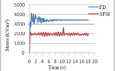
m. While compared to the maximum response obtained by considering soil foundation structure interaction (SFSI) the responses obtained by fixed base analysis (conventional method) are very low. About 98% of increase for displacement in SFSI compared to FB. While comparing the stress levels in FB and SFSI, stress levels are more for FB shown in Fig. 7. The maximum stress at column base for FB is 4013 kN/m2 and for SFSI it is for 5 piles in sand smooth condition 2630 kN/m2. Percentage increase in stress for FB found to be varying between 35-70%. The acceleration of fixed base and soil structure foundation is compared in Fig. 8. From the figure it has observed that increase in response for SFSI when compared to fixed base is because of accounting for the kinematic and inertial interaction. That is in this ground acceleration is getting altered before reaching the surface because of presence of soil that is site effect and also the presence of stiff foundation elements that is kinematic interaction. In the case of soil foundation structure interaction system the presence of soil and foundation make a considerable change in response with a shift of natural period of the system which plays a major role in the response. At the time of shaking there is a change in dynamic characteristics of the soil. The stiffness and damping characteristics of soil may change significantly because of this interaction effect.
Fig. 7. Comparison of stress response of fixed base and soil structure system
Fig. 8. Comparison of acceleration response of fixed base and soil structure system
Stress location
Loose sand ( kN/m2)
Soft clay ( kN/m2)
Smooth Bonded Smooth Bonded
Column
top 8080 8070 8210 8150
Column
base 1340 1200 2630 1820 Pile
head 560 80 1070 1040
177
5. CONCLUSIONS
The following conclusions are obtained by conducting dynamic analyses on pile supported modeled building frame.
1. As the pile number in a group increases the displacement and stress decreases. The maximum percentage decrease of displacement is 72% for clay in smooth condition. For stress it is 99% for sand in bonded condition.
2. Pile soil interface effect considered in terms of smooth and bond condition resulted as the displacement and stress for smooth condition more than bonded. The maximum percentage increase in displacement is 19% for single pile in sand and 9% in clay for 5 piles. 3. The stress is maximum at column head and
gets decreases as it reaches the pile tip. The maximum decrease of 100% was observed for 3 piles in clay under bonded condition. 4. In single pile the pile head stress is more
than column base stress. For single pile in sand there is a maximum increase of pile head stress, which is 30.25% more than column base stress in smooth. In clay also maximum percentage increase for smooth, the value is 21%.
5. Acceleration of the soil structure system in smooth condition more than the bonded condition.
6. After modal analysis the fundamental period obtained for fixed based structure found to be less than soil-structure system. Hence by neglecting the effect of soil the fundamental period of the system is under estimated. 7. Displacement and acceleration obtained by
considering fixed base structure is very less compared to soil structure interaction. The displacement increases in the range of 78-98% when effect of SFSI considered. Stress is more for fixed base analysis compared to SFSI, at the column base the stress is increased in the range of 35-70%.
REFERENCES
[1] Agarwal, D. K.; Chore, H. S.; Dode, P. A. (2014): Interaction analysis of a building frame supported on pile groups. Coupled Systems Mechanics, 3(3), pp. 305-318.
[2] Arefi, M. J. (2008): Effects of Soil-Structure Interaction on the Seismic Response of Existing R.C. Frame Buildings. M.Sc. Thesis in
Earthquake Engineering & Engineering Seismology, Istituto Universitario di Studi Superiori di Pavia.
[3] Asha, J.; Salinitha, K. (2013): Investigation on Seismic Response of End Bearing Piles. Proceedings of Indian Geotechnical Conference, Roorkee, pp. 22-24.
[4] Cai, Y. X.; Gould, P. L.; Desai, C. S. (2000): Nonlinear analysis of 3D seismic Interaction of soil-pile-structure systems and application. Engineering Structures 22, pp. 191-199.
[5] Chore, H. S.; Ingle, R. K. (2008): Soil Structure Interaction Analyses of Pile Supported Building Frame. AJSTD, 25(2), pp. 457-467.
[6] Chore, H. S.; Ingle, R. K.; Sawant, V. K. (2010): Building frame pile foundation soil interaction analysis: A parametric study. Interaction and Multiscale Mechanics. ASCE, 3(1), pp. 55-79. [7] Ghambir, M. R. (2011): Fundamentals of
Reinforced Concrete Design. Prentice Hall of India private limited.
[8] IS 456 (2000): Plain and reinforced code of practice, Bureau of Indian standards.
[9] IS 2911-Part 1-(1980): Code of practice of design and construction of pile foundation, Bureau of Indian standards.
[10] Lu, X.; Chen, B.; Li, P.; Chen, Y. (2003): Numerical Analysis of Tall Buildings Considering Dynamic Soil‐Structure Interaction.ʺ J. Asian Archit. Build, 2(1), pp. 1-8. [11] Murthy, V. N. S. (2008): Soil Mechanics and Foundation Engineering. Cbs Publishers & Distributors.
[12] Reddy, R. C.; Rao, G. T. D. (2012): Study of soil interaction in a model building frame with plinth beam supported by pile group. International Journal of Advanced Structural Engineering, Springer, 4(11).