Design of DC-DC Converter System for
Structural Vibration Control
Ramya H M1, Siva Subba Rao Patange2, Dr. S Raja2, Aravindu B2, Mahommed Toufiq A
Hindustani2 , Dr. Meera A1
BMS College of Engineering, Bengaluru, Karnataka, India1 CSIR-National Aerospace Laboratories, Bengaluru, Karnataka, India2
ABSTRACT: This paper presents the design of DC-DC Converter system for structural vibration control. The structural vibration control is carried out using the phenomenon called as the Active Vibration Control. The biasing input voltage range for the DC-DC converter is from 28 V to 32 V, and the output voltage range is from -40V to +150V. This is achieved by using a modified Buck-Boost DC-DC converter. Reason for selecting the buck-boost converter is that it converts DC voltage efficiently to either a lower or higher voltage. So it is best suitable for AVC applications which require both positive and negative voltage. The commonly used buck-boost converter requires a single controllable switch like MOSFET. The switching frequency range for the converter is of 1 kHz. The output voltage is observed for different PWM signal variation. The DC-DC buck-boost converter is designed in MATLAB/Simulink platform.
KEYWORDS: DC-DC converter, AVC, Buck-Boost Converter, SIMULINK.
I. INTRODUCTION
A DC-to-DC converter is an electronic circuit or electromechanical device that converts a source of direct current (DC) from one voltage level to another. It is a type of electric power converter. Power levels range from very low to very high. DC to DC converters is used in portable electronic devices such as cellular phones and laptop computers, which are supplied with power from batteries primarily. Such electronic devices often contain several sub-circuits, each with its voltage level requirement different from that supplied by the battery or an external supply. The battery voltage declines as its stored energy are drained. Switched DC to DC converters offer a method to increase voltage from a partially lowered battery voltage thereby saving space instead of using multiple batteries to accomplish the same task[8].
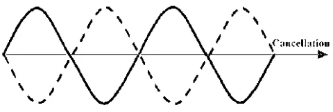
Active vibration control (AVC) is the active application of force in an equal and opposite fashion to the forces imposed by external vibration. Active vibration control is based on the principle of superposition and destructive interference[1]. It is achieved by application of identical force but exactly reverses in phase to the offending vibration as shown in figure 1. As a result, vibrations cancel each other.
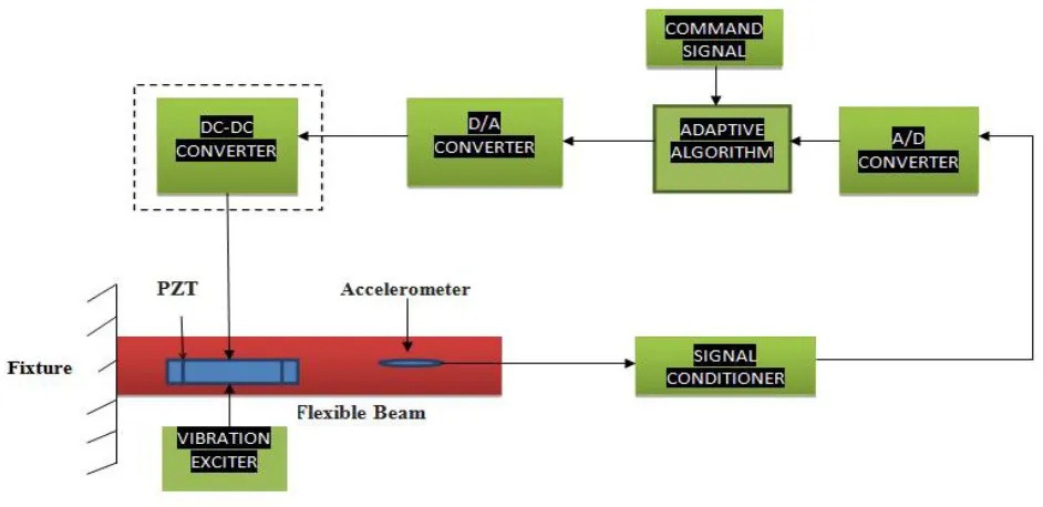
The block diagram consists of vibration exciter, PZT, Accelerometer, signal conditioner, A/D converter, Adaptive algorithm, command signal, D/A converter, DC-DC converter/Amplifier. Vibration exciter is a device which generates vibration of natural frequency at the fixed end of a flexible beam (DUT). Accelerometer is sensor used to measure vibration produced by the cantilever beam. The Signal from accelerometer is given to the signal conditioner, which amplifies the signal. The amplified signal is fed to the A/D converter which converts the analog signal into digital signal. The adaptive algorithm is implemented by using microcontroller so that it generates the opposite signal to nullify the vibrations generated at the flexible beam. The D/A is used to convert the digital signal to analogue and this signal is given to the DC-DC Converter. The DC-DC Converter converts unregulated DC output to regulated DC. Also, it amplifies the signal which is fed back to PZT patch. PZT is a device which converts electrical to mechanical signals, which is at the fixed end of the cantilever beam. The PZT and vibration exciter are placed perpendicular to each other to minimize the phase difference between them. The block diagram for active vibration control system is as shown in figure 2.
Fig 2:-Block diagram of Active Vibration Control system with DC-DC converter.
II. METHODOLOGY OF DC-DC CONVERTER
Fig 3: Basic Block diagram of DC- DC Converter
A few applications of interest of DC-DC converters are where 5 V DC on a personal computer motherboard must be stepped down to 3 V, 2 V or less for one of the latest CPU chips; where 1.5 V from a single cell must be stepped up to 5 V or more, to operate electronic circuitry. In all of these applications, there is a need to change the DC energy from one voltage level to another, while wasting as little as possible in the process. In other words, to perform the conversion with the highest possible efficiency, DC-DC Converters are needed because unlike AC, DC cannot simply be stepped up or down using a transformer. In many ways, a DC-DC converter is the DC equivalent of a transformer. They essentially just change the input energy into a different impedance level. So whatever the output voltage level, the output power all comes from the input; there is no energy manufactured inside the converter [3].
III. TYPES OF DC-DC CONVERTER
Basically there are three types of DC-DC converter 1. BUCK converter (Step down converter) 2. BOOST converter (Step up converter) 3. BUCK-BOOST converter.
1. BUCK Converter: The system operates in buck mode when the required output voltage is less than the input voltage. The circuit is controlled with PWM pulses as shown in figure 4. In a buck converter, MOSFET is used as a switch [4].
Fig 4: Circuit of BUCK converter
2. BOOST converter: The circuit operates in boost mode when the required output voltage is greater than the input voltage as shown in figure 5. The system is controlled by the PWM pulses. In boost converter MOSFET is used as a switch[5].
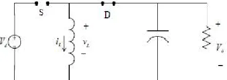
3. BUCK-BOOST Converter: A buck-boost converter is a DC-DC power converter capable of converting the supply voltage source to higher and lower voltages to a load terminal[6]. The mean output voltage is greater or smaller than the input voltage, depending on the duty cycle D. It is a combination of the buck converter topology and a boost converter topology in cascade. The output to input conversion ratio is also a product of ratios in buck converter and the boost converter. The output voltage is controlled by controlling the parameter D defined as the ratio of on time of the switch to the total switching period. This shows the output voltage to be higher or lower than the input voltage, based on the duty-ratio D. The circuit diagram of BUCK-BOOST converter is shown in figure 6.
Fig 6: Circuit of buck-boost converter
A. Circuit operation when the switch is closed : When the switch S is ON, the supply current flows through the path S and L. The current through both source and inductor increase and are same. The polarity of the induced voltage is same as that of the input voltage. The circuit when the switch is turned on is shown in figure 7.
Fig 7: Circuit when switch is closed
B. Circuit operation when the switch is opened : When the switch S is OFF, the inductor current tends to decrease, with the polarity of the induced emf reversing and is negative, now the polarity of the output voltage being opposite to that of the input voltage. The current flows through the load. The output voltage remains nearly constant, as the capacitor is connected across the load. The circuit when the switch is turned off is shown in figure 8.
IV. DESIGN PARAMETERS AND SIMULINK IMPLEMENTATION
The designing parameters for the DC-DC converter are
• Input signal: The signal from AVC system is taken which is regarding millivolts and maximum voltage up to 20 V.
• Input excitation voltage: The input voltage range for the DC-DC converter is from 28 V to 32 V DC.
• Output voltage: The amplified voltage from the converter is from -40 V to 150 V DC.
• Operating frequency: The operating frequency for the designed converter is 1 kHz. Simulink Implementation:-
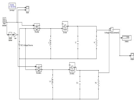
Fig 9: Simulink design of DC-DC Converter
reverse polarity. The operation voltage required for Active Vibration Control (AVC) is in the range of -40 V to +150 V. So this voltage is generated from a 28 V to 32 V input voltage using control input signal from the PWM generator. The two converters operate simultaneously such that one with duty-cycle D and the other is with (1-D) output voltage across the load. Hence it is able to get both positive and negative voltages. Voltage measurement is used to measure the voltage and voltage wave form is observed on scope.
V. RESULTS AND DISCUSSION
The simulation results for the input voltage, for the different pulse width signal, are shown below,
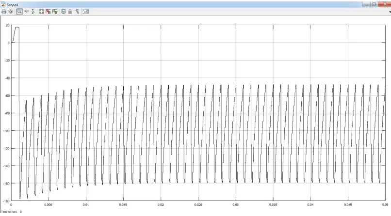
Case 1:- For 20% of PWM signal
For operation voltage of 28 V with 20% of PWM signal, the output voltage produced is -46.77 V as shown below.
Case 2:- For 40% of PWM signal
For operation voltage of 28 V with 40% of PWM signal, the output voltage produced is16.51 V as shown below.
Fig 11: Simulation output for pulse width 40%
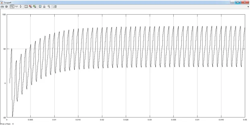
Case 3:- For 60% of PWM signal
For operation voltage of 28 V with 60% of PWM signal, the output voltage produced is83.09 V as shown below.
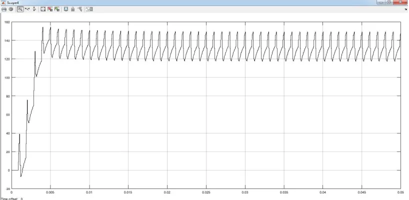
Case 4:- For 80% of PWM signal
For operation voltage of 28 V with 80% of PWM signal, the output voltage produced is 145 V as shown below.
Fig 13: Simulation output for pulse width 80%
VI. CONCLUSION
The DC-DC converter is designed using Simulink platform. The specific application of Active vibration control is achieved by designing a converter of output range -40 V to 150 V from input excitation voltage of 28 V to 32 V for different pulse width signal. The different cases of the pulse width signal and the output voltage is observed as shown below figure 14.
Fig 14: Pulse width signal vs. Output voltage graph.
3. For 60% PWM signal with the operation voltage of 28 V, the output voltage observed is 83.09 V 4. For 80% PWM signal with the operation voltage of 28 V, the output voltage observed is 145 V
ACKNOWLEDGEMENT
The authors would like to thank the Director, Mr. Jitendra J Jadhav CSIR-National Aerospace Laboratories for his persistence to carry out the work and Dr. Satish Chandra, Head Structural Technologies Division (STTD) for providing all the facilities for completing this work. My Special thanks to Ms.Radhika Nadiger, Structural Technologies Division (STTD), CSIR-National Aerospace Laboratories, for their help.
REFERENCES
[1] Sen M. Kuo and Dennis R. Morgan, “Active Noise Control: A Tutorial Review”, Proceedings of the IEEE, Vol. 87, No. 6, June 1999.
[2] MEHEDI HASAN TUSHAR ID-09221205, “COMPARATIVE STUDY ON DC-DCCONVERTERS”.
[3] R. D. Middlebrook, Power electronics: topologies, modeling, and measurement, Proc. IEEE Int. Symp. Circuits Syst., April 1981. [4] Muhammad H. Rashid, “Power Electronics, Circuits, Devices, and Applications”, Third Edition, Pearson Education, Inc., 2004.
[5] Koutroulis, K. Kalaitzakis and N. C. Voulgaris, “Development of a microcontroller based photovoltaic maximum power point tracking system,” IEEE Trans. On Power Electronics, vol. 16, no. 1, pp. 46-54, 2001.
[6] Qun Zhao and Fred C. Lee : "High-Efficiency, High Step-Up DC-DC Converters", IEEE Transactions on Power Electronics, Vol.18, No.1 pp.65-73 (2003)
[7] Y Sam Joel∗, Dr. H V Saikumar† and Siva Suba Rao Patange, “Design & Performance Analysis of Fuzzy Based MPPT Control Using Two-Switch Non Inverting Buck-Boost Converter”, 2016 International Conference on Electrical Power and Energy Systems (ICEPES) Maulana Azad National Institute of Technology, Bhopal, India. Dec 14-16, 2016