Design, Operation and Flexible Control of a
DSTATCOM Operating in Voltage Control
Mode
Vishal M. Joshi1, C.O.Reddy2
PG Student [EE], Dept. of EE, Matsyodari College of Engineering, Jalna, Maharashtra, India1 Assistant Professor, Dept. of EE, Matsyodari College of Engineering, Jalna, Maharashtra, India2
ABSTRACT: A distribution static compensator (DSTATCOM) is used for load voltage regulation and its performance mainly depends upon the feeder impedance and its nature (resistive, inductive, stiff, non-stiff). However, a study for analyzing voltage regulation performance of DSTATCOM depending upon network parameters is not well defined. This paper aims to provide a comprehensive study of design, operation, and flexible control of a DSTATCOM operating in voltage control mode. A detailed analysis of the voltage regulation capability of DSTATCOM under various feeder impedances is presented. Then, a benchmark design procedure to compute the value of external inductor is presented. A dynamic reference load voltage generation scheme is also developed which allows DSTATCOM to compensate load reactive power during normal operation, in addition to providing voltage support during disturbances. Simulation and experimental results validate the effectiveness of the proposed scheme.
KEYWORDS:DSTATCOM, Voltage regulation, load voltage generation, voltage control mode
I.INTRODUCTION
The voltage regulation performance of DSTATCOM mainly depends upon the feeder impedance and its nature (resistive, inductive, stiff, non-stiff). For voltage control mode (VCM) operation of DSTATCOM and/or grid connected inverters, the idea of inserting an external inductor in line has been reported [18], [19]. However, in these schemes, only the concept has been introduced leaving ample scope for further investigation and insight into the design details. The focus of this paper is to provide a detailed design procedure for selecting the external inductor which satisfies several practical constraints, allows DSTATCOM to regulate load voltage in stiff as well as resistive feeder, reduce the current requirement for mitigation of sag, and reduce the system losses. With coordinated control of the load fundamental current, terminal voltage, and voltage across the external inductor, a dynamic reference load voltage generation scheme is presented. This scheme ensures unity power factor (UPF) operation during normal operation and maintains load voltage constant during voltage disturbances. Detailed simulation and experimental results are included to verify the DSTATCOM performance.
OBJECTIVES
The objectives of this project is
To provide a detailed design procedure for selecting the external inductor which satisfy several practical constraints, allows DSTATCOM to regulate load voltage in stiff as well as resistive feeder, reduce the current requirement for mitigation of sag, and reduce the system losses.
With coordinated control of the load fundamental current, terminal voltage, and voltage across the external inductor, a dynamic reference load voltage generation scheme is presented.
This scheme ensures unity power factor (UPF) operation during normal operation and maintains load voltage constant during voltage disturbances.
II. METHODOLOGY
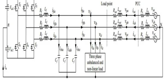
2.1 DSTATCOM in Power Distribution System
Fig. shows power circuit diagram of the DSTATCOM topology connected in distribution system. Ls and Rs are source inductance and resistance, respectively. This inductor helps DSTATCOM to achieve load voltage regulation capability even in worst grid conditions, i.e., resistive or stiff grid. From IEEE-519 standard, point of common coupling (PCC) should be the point which is accessible to both the utility and the customer for direct measurement. The DSTATCOM is connected at the point where load and Lext are connected. The DSTATCOM uses a three-phase four-wire VSI.. Voltages across dc capacitors, Vdc 1 and Vdc 2, are maintained at a reference value of Vdcref.
Fig.1 Phase equivalent circuit of DSTATCOM topology in distribution system
2.2 EFFECT OF FEEDER IMPEDANCE ON VOLTAGE REGULATION
Fig.2 Equivalent source-load model without considering external inductor
To demonstrate the effect of feeder impedance on voltage regulation performance, an equivalent source-load model without considering external inductor is shown in Fig. 2. The current in the circuit is given as
where Vs = Vs ∠δ, Vl = Vl ∠0, Is = Is ∠φ, and Zs = Zs ∠θs, with Vs, Vl, Is, Zs, δ, φ, and θs are rms source voltage, rms load voltage, rms source current, feeder impedance, load angle, power factor angle, and feeder impedance angle, respectively. The three phase average load power (Pl) is expressed as
= [3 ∗ ∗]
Substituting Vl and Is in , the load active power is
= 3 cos( − )
Rearranging above equation, expression for δ is computed as follows:
For power transfer from source to load with stable operation in an inductive feeder, δ must be positive and less than
90◦. Also, all the terms of the second part of (4), i.e., inside cos− 1, are amplitude and will always be positiveThe vector
expression for source voltage is given as follows:
= + ∠( +∅)
A DSTATCOM regulates the load voltage by injecting fundamental reactive current. To demonstrate the DSTATCO voltage regulation capability at different supply voltages for different Rs/Xs, vector diagrams using (5) are drawn in Fig.3. To draw diagrams, load voltage Vl is taken as reference phasor having the nominal value OA (1.0 p.u.). With aim of making Vl = Vs = 1.0 p.u., locus of Vs will be a semicircle of radius Vl. Since, the maximum possible load angle is 90◦ in an inductive feeder, phasor Vs can be anywhere inside curve OACBO. Fig. considers case when Rs/Xs = √3 i.e., θs = 30◦. The area under ACDA shrinks, which shows that with the increase in Rs/Xs from the limiting value,
the voltage regulation capability decreases. In this case the limiting values of Vslimit and IsZs are found to be 0.866 and 0.5 p.u., respectively. Here, maximum possible voltage regulation is 13.4%.
Fig.3 Regulation performance curve of DSTATCOM at different Rs /Xs. (a) For Rs /Xs = 1. (b) For Rs /Xs = √3. (c)
For Rs /Xs = 3.73.
III. SELECTION OF EXTERNAL INDUCTOR FOR VOLTAGE
3.1 Regulation Improvement and Rating Reduction
This section presents a generalized procedure to select external inductor for improvement in DSTATCOM voltage regulation capability while reducing the current rating of VSI. Fig. 4 shows single phase equivalent DSTATCOM circuit diagram in distribution system. With balanced voltages, source current will be
= ∠ − ∠
( + ) + ( + )
= ∠ − ∠
( + )
Where Rsef = Rs +Rext and Xsef = Xs +Xext are effective feeder resistance and reactance, respectively. Rext is equivalent series resistance (ESR) of external inductor, and will be small. With and
= tan
= +
as effective impedance angle and effective feeder impedance, respectively, the imaginary component of Is is given as
With the addition of external impedance, the effective feeder impedance becomes predominantly inductive. Hence, Zsef≈Xsef. Therefore, approximated Isim will be
= sin + sin −
DSTATCOM Power rating (Svsi) is given as follows:
=√3 √2
Where Ivsi is the rms phase current rating of the VSI and Vdc is the voltage maintained at the dc capacitors. The DSTATCOM aims to inject harmonic and reactive current component of load currents. Suppose Ilim is the maximum rms reactive and harmonic current rating of the load, then the value of
Fig.4 Single phase equivalent circuit of DSTATCOM topology with external inductor in distribution system. Compensator current used for voltage regulation (same as Isim) is obtained by subtracting Ilim from Ivsi and given as follows:
= − =√
√
Comparing (8) and (10) while using value of δ from (4), following expression is obtained: =
sin + sin cos cos + 3 √2
√3 −
The above expression is used to compute the value of external inductor. Design example of external inductor, used for this work, is given in next section.
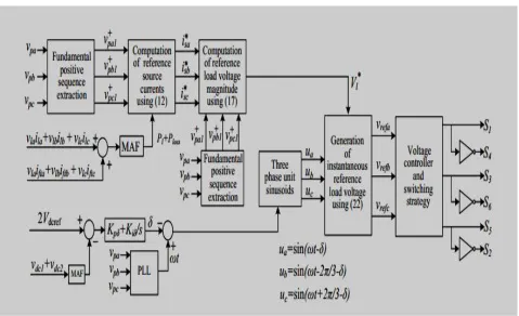
IV. FLEXIBLE CONTROL STRATEGY
is used to control the load angle which helps in regulating the dc bus voltage at a reference value. Finally, three phase reference load voltages are generated.
4.1. Derivation of Dynamic Reference Voltage Magnitude (Vl* )
In conventional VCM operation of DSTATCOM, the reference load voltage is maintained at a constant value of 1.0 p.u. [10]–[12]. Source currents cannot be controlled in this reference generation scheme. Therefore, power factor will not be unity and source exchanges reactive power with the system even at nominal supply. To overcome this limitation, a flexible control strategy is developed to generate reference
SIMULATION PARAMETERS
1) Normal Operation:
It is defined as the condition when load voltage lies between 0.9 to 1.1 p.u. In this case, the proposed flexible control strategy controls load voltages such that the source currents are balanced sinusoidal and VSI does not exchange any reactive power with the source. Hence, the source supplies only fundamental positive sequence current component to support the average loads power and VSI losses.
∗ =
∆ ( + )
=1 ( + + )
=1 ( + + )
The reference source currents must be in phase with the respective phase fundamental positive sequence PCC voltages for achieving UPF at the PCC. Instantaneous PCC voltage and reference source current in phase-a can be defined as follows:
Fig.5 Block diagram of proposed flexible control strategy
∗ =√2 ∗ sin −
Where V+pa1 and ϕ+pa1 are rms voltage and angle of fundamental positive sequence voltage in phase-a, respectively.
= − ∗
V. SIMULATION RESULTS
The parameters of DSTATCOM compensated distribution system are given in Table I. Usual scenario in distribution system having resistive feeder impedance are considered. PSCAD software is used to simulate the system. Firstly, the DSTATCOM is operated in conventional VCM, i.e.
1) Without external inductor and 2) with a reference voltage of 1.0 p.u. or 230 V rms. The steady state waveforms of three phase PCC voltages, load voltages, source currents, filter currents, and load currents are shown in Figs. 7(a)-(e), respectively.
EXPERIMENTAL SETUP PARAMETERS
Fig.7 Experimental results. (a) During normal operation (i)-(v). (b) During voltage sag (vi)-(x). (c) During voltage swell (xi)-(xv).
Power in addition to reactive power requirement of the Lext. The THDs in the load currents are 14.5%, 15.3%, and 13.6% for phases a, b, and c, respectively. After the compensation, the THDs in source currents are reduced to 2.4%, 2.7%, and 2.4%, respectively in phases a, b, and c. The filter and load currents are shown in Figs. 8(iv) and (v), respectively. These waveforms validate the performance of flexible control strategy as
1) source does not exchange reactive power from the system,
2) filter does not supply additional current and reduces system losses, and 3) UPF is maintained at the PCC.
These features are not available in conventional DSTATCOM operating in VCM. Approximate losses in the system are given as follows:
= 3 + ( ) + ( )
The waveforms of load voltages are shown in Fig. 8(vii).
This guarantees continuous, flexible, and robust operation of the load. The source currents are increased during sag period as illustrated in Fig. 8(viii). Fig. 8(ix) shows the filter currents which increase during sag period to support the load voltage. The load currents waveforms presented in Fig. 8(x) is nearly constant during entire operation. Once the sag is removed at t = 0.38 s, slowly all the waveforms reach the pre-sag values. With the results of Figs. 8(vi)-(x), it can be concluded that the proposed scheme makes load operation continuous.
Source voltage is increased to 1.4 p.u. at t = 0.8 s to create swell. The PCC voltages are shown in Fig. 8(xi). The algorithm detects swell and maintains load voltage at 1.1 p.u. The waveforms are shown in Fig. 8(xii). The waveforms of the source, filter, and load currents are shown in Figs. 8(xiii)- (xv), respectively. The filter currents increase during swell which increases the source currents as well. Load currents are nearly constant throughout the operation. Once sag is removed, it is detected by the algorithm and system is brought to the steady state conditions. It confirms effectiveness of the proposed scheme.
VI. EXPERIMENTAL RESULTS
A reduced scale experimental prototype, as shown in Fig., is developed to validate the capability of proposed scheme. The parameters of the system are given in Table II. Performance of the DSTATCOM and flexible control strategy at the steady state is shown in Fig. 10(a). The three phase PCC voltages, load voltages, source currents, filter currents, and load currents are shown in Figs. 10(i)-(v), respectively.
The scheme makes both three phase source currents as well as load voltages balanced and sinusoidal. The THDs in the load currents are 18.1%, 17.5%, and 19.4% for phases a, b, and c, respectively. After the compensation, the THDs in source currents are reduced to 3.2%, 3.6%, and 3.4%, in respective phases. Also, source currents are in-phase with the respective PCC voltages. It confirms that the source does not exchange any reactive power with the system. Therefore, the filter currents consist of harmonic and reactive component of load current in addition to reactive current requirement of external inductor. The performance of the proposed scheme during voltage sag is shown in Fig. 10. The PCC voltages shown in Fig. are decreased to 0.6 p.u. during the sag period. The control strategy detects sag and maintains load voltage, as shown in Fig. 10(vii), at 0.9 p.u. during the entire sag period. Moreover, no transient in the load voltage is noticed. It can be observed from Fig. That the source currents are increased during the sag duration. It is due to the fact that the compensator supplies reactive current, as shown in Fig, towards the source to maintain load voltage at a constant value. The load currents are shown in Fig. 10(x). These are drawn as per the load requirement.
VII. CONCLUSION
This paper has presented design, operation, and control of a DSTATCOM operating in voltage control mode (VCM). After providing a detailed exploration of voltage regulation capability of DSTATCOM under various feeder scenarios, a benchmark design procedure for selecting suitable value of external inductor is proposed. An algorithm is formulated for dynamic reference load voltage magnitude generation. The DSTATCOM has improved voltage regulation capability with a reduced current rating VSI, reduced losses in the VSI and feeder. Also, dynamic reference load voltage generation scheme allows DSTATCOM to set different constant reference voltage during voltage disturbances. Simulation and experimental results validate the effectiveness of the proposed solution. The external inductor is a very simple and cheap solution for improving the voltage regulation, however it remains connected throughout the operation and continuous voltage drop across it occurs. The future work includes operation of this fixed inductor as a controlled reactor so that its effect can be minimized by varying its inductance.
REFERENCES
1. M. H. Bollen, Understanding power quality problems. vol. 3, IEEE press New York, 2000.
2. S. Ostroznik, P. Bajec, and P. Zajec, “A study of a hybrid filter,” IEEE Trans. Ind. Electron., vol. 57, no. 3, pp. 935–942, Mar. 2010.
3. C. Kumar and M. Mishra, “A voltage-controlled DSTATCOM for power quality improvement,” IEEE Trans. Power Del., vol. 29, no. 3, pp. 1499– 1507, June 2014.
4. Q. Liu, L. Peng, Y. Kang, S. Tang, D. Wu, and Y. Qi, “A novel design and optimization method of an LCL filter for a shunt active power filter,” IEEE Trans. Ind. Electron., vol. 61, no. 8, pp. 4000–4010, Aug. 2014.
6. S. Karanki, N. Geddada, Mahesh K. Mishra, and B. Kumar, “A DSTATCOM topology with reduced dc-link voltage rating for load compensation with nonstiff source,” IEEE Trans. Power Electron, vol. 27, no. 3, pp. 1201–1211, Mar. 2012.
7. M. Aredes, J. Hafner, and K. Heumann, “Three-phase four-wire shunt active filter control strategies,” IEEE Trans. Power Electron., vol. 12, no. 2, pp. 311–318, Mar. 1997.
8. B. Singh, K. Al-Haddad, and A. Chandra, “A new control approach to three-phase active filter for harmonics and reactive power compensation,” IEEE Trans. Powe Sys., vol. 13, no. 1, pp. 133–138, Feb 1998.
9. S. Narula, B. Singh, and G. Bhuvaneswari, “Improved power-quality based welding power supply with over current handling capability,” IEEE Trans. Power Electron., vol. 31, no. 4, pp. 2850–2859, April 2016.
10. H. Fujita and H. Akagi, “Voltage-regulation performance of a shunt active filter intended for installation on a power distribution system,” IEEE Trans. Power Electron., vol. 22, no. 3, pp. 1046–1053, May 2007.
11. R. Gupta, A. Ghosh, and A. Joshi, “Performance comparison of VSCbased shunt and series compensators used for load voltage control in distribution systems,” IEEE Trans. Power Del., vol. 26, no. 1, pp. 268– 278, Jan. 2011.
12. Mahesh K. Mishra, A. Ghosh, and A. Joshi, “Operation of a DSTATCOM in voltage control mode,” IEEE Trans. Power Del., vol. 18, no. 1, pp. 258–264, Jan. 2003.
13. A. Jain, K. Joshi, A. Behal, and N. Mohan, “Voltage regulation with STATCOMs: modeling, control and results,” IEEE Trans. Power Del., vol. 21, no. 2, pp. 726–735, Apr. 2006.
14. B. Singh and G. Kasal, “Solid state voltage and frequency controller for a standalone wind power generating system,” IEEE Trans. Power Electron., vol. 23, no. 3, pp. 1170–1177, May 2008.
15. B. Singh, S. Murthy, and S. Gupta, “Analysis and design of statcombased voltage regulator for self-excited induction generators,” IEEE Trans. Energy Conver., vol. 19, no. 4, pp. 783–790, Dec 2004.