ISSN (Print) : 2320 – 3765 ISSN (Online): 2278 – 8875
I
nternational
J
ournal of
A
dvanced
R
esearch in
E
lectrical,
E
lectronics and
I
nstrumentation
E
ngineering
(An ISO 3297: 2007 Certified Organization)
Vol. 5, Issue 8, August 2016
Automatic Airflow Loop Control in Industrial
Gas Burner using LabVIEW
Suguna .T.D1, Sujatha .B.C2, H.Prasanna kumar3
PG Scholar, Department of Electrical Engineering, University Visvesvaraya College of Engineering, Bengaluru, India1
Associate Professor, Department of Electrical Engineering, University Visvesvaraya College of Engineering,
Bengaluru, India2
Assistant Professor, Department of Electrical Engineering, University Visvesvaraya College of Engineering,
Bengaluru, India3
ABSTRACT
:
This paper focuses on automatic air flow loop control in industrial gas burner using a PI controller scheme. Combustion in industrial gas burners is achieved using a non explosive mixture of Liquefied Petroleum Gas (LPG) and air. The LPG is injected to the industrial gas burner with constant pressure from the storage cylinder and the flow rate is controlled using the regulator attached to it. Whereas the air required for combustion is absorbed from the unregulated atmospheric stream. The variation in the ratio of LPG to the air leads to disturbance in combustion and low calorific output in gas burners. To avoid such situation, it is necessary to control air flow with fixed pressure of L.P.G. This is attained using a feedback control loop preferably with a PI control scheme is designed in LabVIEW software environment. CO2/CO ppm measurement is done using gas sensor. Error analysis is done for the PI controller regardingIAE, ISE. Transient analysis is also carried out on the PI control strategy and rise time, peak time is evaluated.
KEYWORDS: Automation of industrial gas burner, PI controller strategy, Combustion controls, emissions, IAE, ISE, Rise Time, Peak Time.
I.INTRODUCTION
Generally in industries which requires the heating, melting, forging etc., will make use of the gas burners for its various applications and safety. The gas burner is a process of converting chemical energy in the fuel to thermal energy. The energy conversion is carried out by burning fuel with the aid of an oxidizer i.e., basically oxygen. During the conversion various bicarbonates which are CO2, NOx and CO are released due to lack of inefficient burning.
Proportionate of fuel and oxygen is the main reason behind the amount of bicarbonates released. Since the industrial gas burner is a closed process the oxygen is externally supplied to it hence maintaining the proper proportionate is major issue in industries. Even though the CO2 is natural outcome of any fuel combustion the other gases NOx and CO
ISSN (Print) : 2320 – 3765 ISSN (Online): 2278 – 8875
I
nternational
J
ournal of
A
dvanced
R
esearch in
E
lectrical,
E
lectronics and
I
nstrumentation
E
ngineering
(An ISO 3297: 2007 Certified Organization)
Vol. 5, Issue 8, August 2016
controlled by applying PID controller. P, PI, PID controller are applied to compare the efficiency of the controller. Simulated results are compared [2]. The process plant consists of industrial gas burner, air blower, and actuator. 3 phase 415 volt motor actuates the given process system which helps in generating a constant air pressure to the burner.
The experiment is conducted to measure the associated level of emissions for burner. Test conducted on the burner shows emissions were obtained depending on the rate of gas valve opening without monitoring the air flow. The level of emissions released also depended on the amount of fuel used and the condition of combustion of the fuel. The emissions released are low and within permissible standards, mainly for the ½ gas valve opening operation which is identified as the optimum operating condition for the burner [3]. Flames formed by combustion of gaseous fuels with the air it will take two forms: premixed flames and diffusion flames. Premixed flames occur when fuel and the oxidizer are mixed upstream of the delivery to the combustion zone. Diffusion flames occur when the fuel and oxidizer are separately delivered to the combustion zone. Premixed flames are cleaner and burn more intensely, but the operating range is narrower than diffusion flame [5], therefore diffusion flame is implemented.
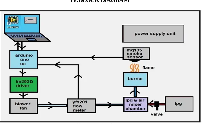
III. HARDWARE SETUP
For constant air supply system brushless dc air blower is used, driven from 12 v .4 amps dc supply. The air from the blower is taken through the pipe for a flow meter. From the flow meter air is concentrated in a volume of box. Constant air flow is supplied to the combustion chamber because it is driven at constant speed from PWM mode.
The air supply hose from the air blower and the gas supply hose from the gas cylinder were connected to the burner. Burner
mounted on a support with nozzle projecting into the combustion chamber. Chimney outlet is connected to the air quality gas sensor in combustion chamber .Gas is valve is set to full opening while air blower is running with PWM mode with constant input the burner was ignited and emission readings were taken and when the flame has become bluish. Implemented hardware are setup as shown in Fig1.
Flow sensor (YF-S201): This sensor is solidly constructed and provides a digital pulse each time an amount of water passes pipe. But in this case it is used for measuring the air flow. By measuring the each pulse air flow output is calculated in L/Min. It is easily connected to a microcontroller for monitoring air usage .PWM digital output pulse is converted into the L/min using the formula: pulse frequency (HZ)/7.5=Flow rate in L/min.
MQ-135 gas sensor: MQ-135 sensor made of SnO2 layer as gas-sensing material its conductivity is lower in clean air. The conductivity of the gas sensor increases along with the rise in concentration of the gas pollutants. After combustion of LPG emission contains CO2, CO, Nox, and also HC (hydro carbons).This sensor measures all these emissions in PPM.
Software: LabVIEW PID toolkit, makerhub Linx, PWM VI, arduino IDE.
Arduino Uno: ATmega328, it has 6 pwm output pins, 6 analog inputs, operating at 5v, 7-12 input voltage
ISSN (Print) : 2320 – 3765 ISSN (Online): 2278 – 8875
I
nternational
J
ournal of
A
dvanced
R
esearch in
E
lectrical,
E
lectronics and
I
nstrumentation
E
ngineering
(An ISO 3297: 2007 Certified Organization)
Vol. 5, Issue 8, August 2016
Fig.1 Hardware setup
ISSN (Print) : 2320 – 3765 ISSN (Online): 2278 – 8875
I
nternational
J
ournal of
A
dvanced
R
esearch in
E
lectrical,
E
lectronics and
I
nstrumentation
E
ngineering
(An ISO 3297: 2007 Certified Organization)
Vol. 5, Issue 8, August 2016
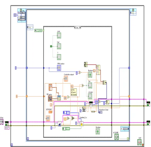
IV.IMPLEMENTATION
The following subVIs are used for PI, PID control scheme shown in fig .3
Flow sensor VI: This subVI takes the input from flow sensor and measures the air flow rate in terms of L/min
PWM VI: This sub VI gives the duty cycle of PWM and analog output on pin number 3 of arduino uno.
(a) (b)
Fig.3 (a) flow sensor VI (b) PWM VI
Designing of PI control scheme in LabVIEW
In PI controller there are two tuning parameters to adjust integral action eliminates offset. Introducing derivative gain produce a oscillation compared to PI controller.
In LabVIEW same PID toolkit is used for PI controller only derivative constant is removed .Tuning parameters are determined by trial and error with Z-N method.
PI controller tuned for following parameters gain KP =1.5, Ti=0.08 and it is reached the desired system response.
PID is tuned for the following parameters gain K P=1, Ti=0.05,Td=0.009
ISSN (Print) : 2320 – 3765 ISSN (Online): 2278 – 8875
I
nternational
J
ournal of
A
dvanced
R
esearch in
E
lectrical,
E
lectronics and
I
nstrumentation
E
ngineering
(An ISO 3297: 2007 Certified Organization)
ISSN (Print) : 2320 – 3765 ISSN (Online): 2278 – 8875
I
nternational
J
ournal of
A
dvanced
R
esearch in
E
lectrical,
E
lectronics and
I
nstrumentation
E
ngineering
(An ISO 3297: 2007 Certified Organization)
Vol. 5, Issue 8, August 2016
V.EXPERIMENTAL RESULTS AND COMPARISON
Set point tracking is done for PI and PID controllers and corresponding IAE, ISE is calculated for both controllers
Fig .5(a)
Fig.5 (b)
ISSN (Print) : 2320 – 3765 ISSN (Online): 2278 – 8875
I
nternational
J
ournal of
A
dvanced
R
esearch in
E
lectrical,
E
lectronics and
I
nstrumentation
E
ngineering
(An ISO 3297: 2007 Certified Organization)
Vol. 5, Issue 8, August 2016
A change in step input is done for PI and PID controllers. The following results are tabulated for set point changes from 4-5cms, 5-6cms and 6-7cms.
PI
PID
IAE
4-5 cm
19.05
28
5-6 cm
11.92
21.2
6-7 cm
21.71
31.4
ISE
4-5 cm
10.61
12.2
5-6 cm
4.36
10.36
6-7 cm
14.1
17.5
Table.1 IAE and ISE for PI and PID controller
The IAE, ISE is calculated for both PI and PID controller. Maximum IAE for PID is found to be 31.4 and for PI is 21.71.Similarly ISE for PID is 17.5 maximum in comparison to 14.1 PI controller.
Table2. Transient response of PI and PID control strategy
Transient response results helps in identifying the better controller. The obtained transient response results for different controller techniques are tabulated in Table 2. Rise time of the PI controller is less compared to PID also the peak time and percentage of overshoot also has considerable good performance in PI control scheme. Hence PI controller gives better transient response to the system.
Parameters
PI
PID
Rise time(in sec)
20.5
25.5
Peak time(in sec)
38.5
56
Percentage
of
peak
overshoot(in sec)
ISSN (Print) : 2320 – 3765 ISSN (Online): 2278 – 8875
I
nternational
J
ournal of
A
dvanced
R
esearch in
E
lectrical,
E
lectronics and
I
nstrumentation
E
ngineering
(An ISO 3297: 2007 Certified Organization)
Vol. 5, Issue 8, August 2016
2. Mr. Bhosale P. P. Shivaji University Satara, India, “Automatic control of air pressure loop in industrial gas burner”. International Conference on Convergence of Technology ,2014
3. Ighodalo Osagie, Amunega Ibrahim, Lawani Monday, Onaghinor Sidney, and Ogboi Terry,“Temperature and Emissions Measurements for a Gas Burner” Journal of Emerging Trends in Engineering and Applied Sciences ,2013
4. Huang hui ming, Liu he sheng, Liu guo ping , “Controller Design for Constant Air Pressure”, International Conference on Energy and Environment Technology,2009
5. Hussien Zaky Barakat, Mohamed Refaat Salem, Abdelaziz Morgan and Hany Elsayed Saad* “ Study of effects of burner configuration and jet dynamics on characteristics of inversed diffusion flames”, journal of Mechanical Engineering Research,2013.
6. Maria Grazia De Giorgi n, Aldebara Sciolti,Stefano Campilongo , Antonio Ficarella, “Experimental data regarding the characterization of the flame behavior near lean blowout in a non-premixed liquid fuel burner”, ELSEVIER journal ,2015.
7. L.Ljung, “Identification of control: Simple process model,” Decision and control 2002, Proceedings of 41st IEEE conference on (Volume:4). 8. J. Mikles, M., A Treatise on Process modeling, identification, and control; Springer, 2007, pp.240–246.
9 Ronald S. Burns, “Advanced control engineering”, Butterworth-Heinemann, 2001, pp. 81–90.
10. Feng qing hua, Chen hai yun, Lu tong da, lai yang yue xing, “Fuzzy immune PID control for processes with large time delay ,” Electronic Instrumentation Customer, 2008, Vol.15(3),pp.45-47.
11. Malcolm barnes, “Practical variable speed drives & power electronics”, Newnes An imprint of Elsevier, 2003, pp. 45–50.