N O N - L I N E A R V E R T I C A L V I B R A T I O N S O F W W E R 4 4 0 M O D E L 2 3 0 A N D 2 1 3 R E A C T O R S
I N T E R N A L S
Hlavfi6 Z d . (1), Z e m a n V l . (1), Pe6inka L. (2~ (1)
(2) University of Westbohemia in Pilsen, Czech Republic Nuclear Research Institute Re~ plc, Czech Republic ABSTRACT
In this paper the vertical stability of WWER Model 230 and 213 reactors internals is analysed. The stability depends on the reliable function of springs of core hold-down/upper internals unit. The application of the vibration theory of non- linear systems proved that decreasing of the second eigen-frequency can be interpreted as a diagnostic symptom of possible disturbances of joints between reactor internals.
1. I N T R O D U C T I O N
The operational problem of WWER 440 Model 230 and 213 reactors (Russian types of PWR) is to ensure the stability of the reactor internals in vertical direction, see Fig. 1. The core barrel is reliably fixed in the reactor pressure vessel by the toroidal tubes with the vertical stiffness kTT, but the lower part of the core barrel, the secondary core barrel and the core hold-down/upper internals units is fixed against uncontrolled vertical motion only by vertical force of hold-down spring units. It is well know [ 1, 2] that the non-correct assembling of core hold-down/upper internals unit after refuelling can induce excessive vibrations of reactor internals. In some cases, these vibrations may result in serious and safety relevant damages of guide lugs [1], see Fig. 1. It is the authors' opinion that this phenomenon can be early recognised by the measurements of reactor pressure vessel and internals vibrations in vertical direction using standard diagnostic system.
The purpose of this paper is
- to present the mathematical model for the assessment of the vertical vibrations of the reactor pressure vessel and reactor internals
- to develop diagnostic criteria for early detection of instabilities in vertical vibrations of the reactor internals. 2. M A T H E M A T I C A L M O D E L
The lumped-mass mathematical model with 13 th degree of freedom is illustrated in Fig. 2. Masses m l , . . . , m5 model following rigid bodies: reactor pressure vessel (RPV), core barrel (CB), lower part of core barrel (LPCB) with secondary core barrel (SCB) and fuel assemblies (FA) and finally core hold-down/upper internals unit (CHD). Masses mLDi, i = 1, 2, 3, 4 together with related stiffnesses kLDi model upper part of reactor (see Fig. 3) which serve for lifting of RPV top head before refuelling.
The control rod driving mechanism (CRDM) and CRDM tubes are modelled as four-point discrete mass system with masses mCRDMTi and stiffnesses kCRDMTi , i = 1, 2, 3, 4. Stiffness kLD,CRDMT represents joint of CRDM tubes top with plate linked to upper ring LD3. The rigid bodies m l . . . , m5 are joined with springs. Their stiffnesses are denoted as k, k2.1, k32, k4.1, k5.3, kxT and kcHD. Note that stiffnesses k2.1, k32 and k53 may be in general non-linear. The coordinate system is established in following manner: y (absolute coordinate of the mass ml), y21 (relative coordinate of the mass m2 against mass m l ) , Y3.2, Y4.1, Y5.3 (again relative coordinates between related masses), YLDi, YCRDMTi (relative coordinate of masses mLDi, mCRDMTi against mass m4).
Under above-mentioned assumptions the equation of motion of the system according to Figs. 2 and 3 can be written as
M it + K q = 0 (1)
where q denotes the vector of generalised coordinates. The mass matrix M takes form
SMiRT 16, Washington DC, August 2001
Paper # 1392M ~__
m m B m c m D m 5 mLD 1 mLD 2 mLD 3 mLD 4 mCDlaklT1 mCDRMT2 mCDRMT3 mCDRMT4
m B m B m C 0 m 5 0 0 0 0 0 0 0 0
m c m C m c 0 m 5 0 0 0 0 0 0 0 0
m D 0 0 m D 0 mLD 1 mLD 2 mLD 3 mLD 4 mCDRMT1 mCDRMT2 mCDRMT3 mCDRMT4
m 5 m 5 m 5 0 m 5 0 0 0 0 0 0 0 0
mLD 1 0 0 toLD 1 0 toLD 1 0 0 0 0 0 0 0
toLD 2 0 0 toLD 2 0 0 toLD 2 0 0 0 0 0 0
m L D 3 0 0 mLD 3 0 0 0 mLD 3 0 0 0 0 0
toLD 4 0 0 mLD 4 0 0 0 0 toLD 4 0 0 0 0
mCRDMT1 0 0 mCRDMT1 0 0 0 0 0 mCRDMT1 0 0 0
mCRDMT2 0 0 mCRDMT2 0 0 0 0 0 0 mCRDMT2 0 0
mCRDMT3 0 0 mCRDMT3 0 0 0 0 0 0 0 mCRDMT3 0
_ m C RDMT 4 0 0 m C RDMT 4 0 0 0 0 0 0 0 0 m C RDMT 4 _
4
m = m5 + ~.~ ( m i + mLDi -I- mCRDMTi ) i s total m a s s o f the reactor, mB = m 2 + m3 + ms, m c = m3 + ms, mD = m4
w h e r e +
i=1 4
+ Z (mLDi + mCRDMTi). i=
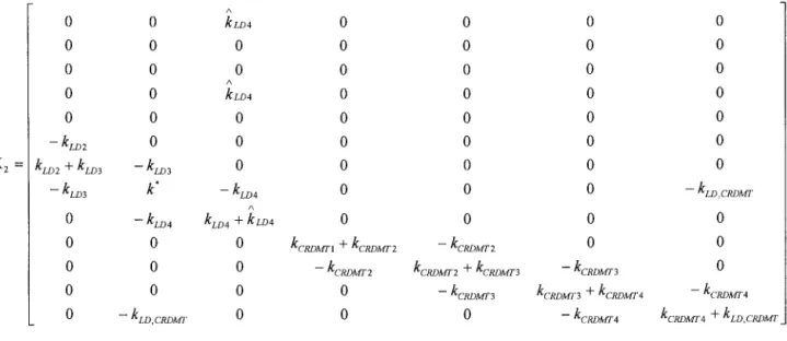
S t i f f n e s s m a t r i x K can be w r i t t e n as K = [K1, K2], w h e r e
K 1 --
0
0 /N
k LD4
0
0
0
0 A
k LD4
0
0
0
0
M
k -b k LD4 0 0 k LD4 0 0
A
k 2.1 -t- k LD 4 -k- k CHD k CHD - k TT - k CHD k CHD 0
kCH D k3, 2 + k c H D - kCH D kCH D 0
A
- kTT -- kCH D -- kCH D k - k c H D 0
k CHD k CHD - k CHD k 5,3 --b k CHD 0
0 0 0 0 kLD 1 + kLD 2
0 0 0 0 - - k L D 2
0 0 0 0 0
A
0 0 k LD4 0 0
0 0 0 0 0
0 0 0 0 0
0 0 0 0 0
K 2 - -
A
0 0 kLD4 0 0 0 0
0 0 0 0 0 0 0
0 0 0 0 0 0 0
A
0 0 kL~4 0 0 0 0
0 0 0 0 0 0 0
- kL~ 2 0 0 0 0 0 0
~ + ~ - ~ o o o o o
- ~ k* - ~,~4 o o 0 - ~ , ~ . ~
A
0 - kLD 4 kLD 4 + ku)4 0 0 0 0
0 0 0 kCRDMrl + kc~Mr 2 - kc~Mr 2 0 0
0 0 0 -- kc~Mr 2 kc~Mr 2 + kc~Mr 3 -- kc~Dgr3 0
0 0 0 0 -- kCRDMr3 kc~Mr 3 + kCRDMr4 -- kCRDMr 4
0 -- kLD,CRDMr 0 0 0 -- kCRDMT4 kCRDMT4 + kLD,CRDMT -
. - . .--. , - - .
where k -- k4,1 + k r r + kLD4, k - kLD 3 + kLD 4 + k~D,CRDMr and kLD 4 is the stiffness of the antiseismic support of the mass LD4. Calculated modal properties are presented in Table 1.
fl = 8 . 6 H z f2 = 22.45 Hz f3 = 27.89 Hz
f4 = 88.4 Hz f5 = 104.9 Hz
RPV, all reactor internals and upper part of reactor head in phase RPV and upper part of reactor head in-phase, all internals out-of phase
RPV, reactor head, CRDM tubes in-phase, core barrel, lower part of CB, core hold- down/upper internals unit and lifting device LD 1 + 4 out of phase
RPV out-of phase against all other components
RPV lower part of CB, reactor head and core hold-down/upper internals unit in-phase, all other components out-of phase. Dominant are out-of phase vibrations of CB and core hold- down/upper internals unit
Table 1: calculated vertical frequencies important for diagnostic measurements
Higher frequencies non-important for diagnostic supposes are f6 = 146.2 Hz; fv = 200.35 Hz; f8 = 261.676 Hz; f9 = 264.54 Hz; fl0 = 282.21 Hz; fll = 395.66 Hz; f12 = 415.14 Hz; f~3 = 596.99 Hz.
3. D I A G N O S T I C S Y M P T O M S O F R E A C T O R I N T E R N A L S V E R T I C A L I N S T A B I L I T Y
It is mentioned in Section 1 that the vertical stability of the lower part of core barrel, the secondary core barrel and the core hold-down/upper internals unit ensure only vertical force of hold-down spring units. From the analysis of numerical values of all elements of the stiffness matrix K one can find out that the stiffness kCHD is approximately hundred-times lesser than all other stiffnesses and that on the principle diagonal kCHD is not alone but always in the sum with much higher stiffnesses. From this reasons a slight change of kCHD in the range + 15% of nominal design value resulting for example from thermal ageing of springs cannot significantly influence both calculated and measured vertical frequencies, see Table 1. But it has been find out from the analysis of eigen-vector matrix, that the significant decreasing of stiffness kCHD under certain value can be recognized on those frequencies at which dominant vibrate reactor internals. This phenomenon can be called diagnostic symptom of reactor internals instability and will be analysed in next section.
e.
character. Under this assumptions the dependence of eigen-frequencies f2i, i = 1, 2, ...., 13 on the deformation of related non- linear spring can be calculated. Taking into account the shape of stiffness characteristic (Fig. 4), the equivalent stiffness monotonously decrease with increasing deformation and thus all eigen-frequencies monotonously decrease.
If we suppose that the system is linear, then velocity of decreasing of eigen-frequencies in the point y = d = -A is proportional to the sensitivity of the selected eigen-frequency to the change of related stiffness. The sensitivity depends on the value of derivation 5 C2i/6 kj, i = 1, 2,. ... 13, j = 2.1, 3.2, 5.3. For numerical calculations one can use following equation [3]
2
6 ~ i 1 6 ~ i 1 r 6 K
_ _ V i
6 k / 2 ~ 6 k ! 2 ~ ; 6 k j
v i (2)
where V i is so called M-norm normalised eigen-vector of linear system. Taking into account quality of matrix K, as a result we obtain
2
6 f2~
vl~
m
6 kj
2 f)t
(3)
where Vli is 1-th coordinate of i-th eigen-vector. Value 1 = 2 is related to j = 2.1, l = 3 is related to j = 3.2 and 1 = 5 is related to j = 5.3.
5. N U M E R I C A L R E S U L T S O F S E N S I T I V I T Y ANALYSIS
For the system illustrated in Figs. 1, 2, 3 and eigen-frequencies according Table 1 following sensitivity parameters have been calculated for j = 2.1 (1 = 2)
10 - 1 0
9E Ol
~ , ...o131
---- = b" k2.1 c~ k2.1 ' ~ k2.1= [0.87; 15.19; 4.7; 0.58; 1.7; 0.015; 0.63; 0.0078; 0.002; 5.85; 4.9 E (-8); 0.0012; 3.9 E (-9)].
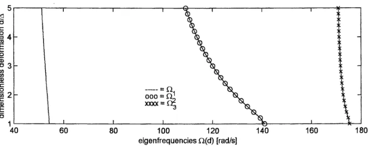
It is evident that the second eigen-frequency f2 depend mostly on the modification of stiffness kzl. Thus one can suppose that velocity of decreasing of f)2 (d2.1) depend mostly on the increase of Id211 - l y2l I > A2.1. This assumption has been numerically verified. Special computer code calculates step-by-step eigen-frequencies f2i as a function I djl
1
(A j , djrnax )" Results for frequencies fl, f2 and f3 are illustrated in the Figs 5 and 6. The agreement with results of sensitivity analyse according equation (3) is excellent.
6. C O N C L U S I O N S
Discrete-mass model with 13-th degrees of freedom has been developed for purposes of the vertical stability analysis of the WWER 440 Model 230 and 213 reactor internals. Main conclusions obtained are
- stability of the core barrel in the reactor pressure vessel is fully ensured by the toroidal tubes
- stability of lower part of the core barrel, the secondary core barrel with fuel assemblies and the core hold-down/upper internals unit depends definitely on the vertical force which generate hold-down spring units
- stiffness of springs of hold-down spring units is approximately hundred-times lesser than all other joint stiffnesses - from this reasons a slight change of stiffness of springs of hold-down spring units resulting for example from thermal
ageing cannot significantly influence the numerical values of vertical frequencies
- application of the theory of discrete lumped mass systems with non-linearities demonstrated that the strong non-linearity influence significantly in our case, the second eigen-frequency f2
- decreasing of this eigen-frequency can be utilized as a diagnostic symptom of a potential vertical instability of the reactor internals
- analyse has been performed only for one non-linearity.
A C K N O W L O D G E M E N T
This work was performed under the contract No 101/00/0345 with the Grant Agency of Czech Republic. R E F E R E N C E S
[1]
[2]
[3]
Lievers P., Schmitt W., Schumann P., Weiss F.P.: Detection of Core Barrel Motion at WWER-440 Type Reactors. Progress in Nuclear Energy (SMORN V., Munich 1987), 21, pp. 89 -96
Altstadt E., Scheffler M., Weiss F.P.: A Vibration Model for the Primary Circuit of WWER-440 Type Reactors Based on Finite Elements
Transactions of SMIRT 13, Int. Conf. on Structural Mechanics in Reactor Technology, Porto Alegre, 1995 Slavik J., Stejskal V., Zeman VI.: Theory of Dynamic of Machines
Czech Technical University Praha Press, 1997 (in Czech language only) FIGURES
spring units
. . . .
toro~da, tubo /
\ ~ ~ ' I ... i t ~ t t l J
!1!
[}! 'It'
core
. . .
barrel (CB)
/
~
,,I
~ ! I ! '
! il!!ll!li! !
guide lugs
t ili!li!!l! !
i ii!!!l!ll! !!
aowo~,a~of
~ HI :'lliililli I
core barrel (LPCB) I
~>. core hold-down/upper internals unit (CHD)
YLD4 T
T
YLD1
y4.,~
~ D
L D 4
LD 2
)
mcmg~7"3
k,z.o ~
k
.
mc~Mre
..
=
~
r ...
kcRD.~rr2
mCRDMTI
k c ~ ~ l
6 )
CB
CHD
ks
RPV
FA
®
yzl
kIR
kFA
stiffness of SCB interval ring
stiffness of springs in FA head
rs¢l % i rrr~.! i q
~ y4.1 k]4.,
.b~ (~4 1
• ..~ ... . ... ~ k,4~,
i " N
N N
iy,,
,.
~ 1 ~
"~ ~o~., ,~,,o . . ~ BI "'~ ... " ...
i
cRD ml__l"
j
. krrkyzl
LD4 F ~4
LD3 ~ ' ~ 3
LD 2 . J _ ~ : yc~rr3 "
~ " o . 2
~ C~OMri
a)
b)
Fig. 3
- d <
F(d)
Latic
des f o r m a t i o n
of joint
i1~- ...
- ~ f ~
• I - A . . .
force
... . . . . . ....
... ~ d
5 I
{ 3 E : O
°I
E5 . . .
~ 3 cO
( / ) E : O
2 - £ :
( I )
E
. . . ,
1 I
. . . I . . . I . . . . "
q
q
! ... I . . . i . . . I ...
i . . . ! ~ I
0 0 0 =
40 60 80 100 120 140 160 180
eigenfrequencies (2(d) [tad/s]
Fig. 5" Skeleton curves of the eigenfrequencies for nonlinear stiffness
k21
. . .
" 0 E 0
: , = 4 -
" 0 3 - 03 03
t--
"~ 2 - - . . . . = : ~ 1
. . . I . . . ~ . . . J . . . I ....
/
0.75 0.8 0.85 0.9 0.95 1 dimensionless eigenfrequency ~(d)/~(A)