International Journal of Research (IJR)
e-ISSN: 2348-6848, p- ISSN: 2348-795X Volume 2, Issue 08, August 2015Available at http://internationaljournalofresearch.org
Symbol Detection in MIMO Systems Using PSOGSA
Optimization Algorithm
Arjun Kumar
M.Tech Research Scholar, ECED, Punjabi University, Patiala, Punjab, India
Er. Amandeep Singh Bhandari
Assistant Professor, ECED, Punjabi University, Patiala, Punjab, India EMAIL: [email protected]
Abstract:-
We present a PSOGSA based algorithm for symbol detection in multi-input multi-output (MIMO) system. Since symbol detection is an NP-hard problem so PSOGSA is particularly attractive as PSOGSA algorithms are one of the most successful strands of swarm intelligence and are suitable for applications where low complexity and fast convergence is of absolute importance. Maximum Likelihood (ML) detector gives optimal results but it uses exhaustive search technique. We show that PSOGSA based detector can give near-optimal bit error rate (BER) at a much lower complexity level. The simulation results suggest that the proposed
detector gives an acceptable performance
complexity trade-off in comparison with ML and VBLAST detectors.
1.1 Introduction
Wireless communication systems have made large developments since the first generation (1G) Systems. Frequency Division Multiple Access (FDMA) was the main techniques used at that level. Similarly, Time Division Multiple Access (TDMA) and Code Division Multiple Access (CDMA) multiple access methods are widely used in today’s communication systems. CDMA is also used in the third generation (3G) schemes. Three multiple access schemes are used to allow users to simultaneously share radio spectrum, which is a finite and essential resource of all wireless communications skills.[1] Nowadays, the wireless system designers are facing several challenges: like the limitation of the radio spectrum, the complexity of wireless propagation environment, the increasing demand for better quality of service (QoS) and higher transmission date rate. Traditional wireless communication schemes
have been made more spectrally efficient through the use of complex coding techniques and algorithms.[2]
1.2 Multiple Input Multiple Output (MIMO)
MIMO systems can be defined simply. Given an arbitrary wireless communication system, we consider a link for which the transmitting end as well as the receiving end is equipped with multiple antenna elements.
The idea behind MIMO is that the signals on
transmit (Tx) antennas at one end and the
receive (Rx) antennas at the other end are “combined” in such a way that the quality (bit-error rate or BER) or the data rate (bits/sec) of the communication for each MIMO user will be improved. Such an advantage can be used to increase both the network’s quality of service and the operator’s revenues significantly. To multiply throughput of a radio link, multiple antennas (and multiple RF channel accordingly) are put at both the transmitter and the receiver. [3]
A MIMO system with similar count of antennas at both the transmitter and the receiver in a point-to-point (PTP) link is able to multiply the system throughput linearly with every additional
antenna. For example, a 3 × 3 MIMO will
double the throughput. [3]
International Journal of Research (IJR)
e-ISSN: 2348-6848, p- ISSN: 2348-795X Volume 2, Issue 08, August 2015Available at http://internationaljournalofresearch.org
efficiency (increase throughput) without
shrinking the coverage area.
The dynamic switching between these modes based on channel conditions is called Adaptive MIMO Switching (AMS). If combined with AAS (Adaptive Antenna System), MIMO can further boost WiMAX performance.
MIMO is widely used in today wireless
communications because all wireless
technologies (PAN, LAN, MAN, and WAN) try to add it to increase data rate multiple times to satisfy their bandwidth-hungry broadband users.
that will most likely make 4G reality are MIMO, OFDM MIMO system will deliver multimedia services (VoIP, video, Internet) at high speed (100 Mbps or more) over end-to-end IP network infrastructure and it will enable seamless handoff between mobile wireless WAN and fixed wireless LAN. [4]
1.3 MIMO System model
A MIMO channel with 𝑁𝑡 transmitters and 𝑁𝑟
receiversis typically represented as a matrix 𝐻
of dimension𝑁𝑟 × 𝑁𝑡, where each of the
coefficients 𝐻𝑛𝑚 represents the transferfunction
from the nth transmitter to the 𝑚𝑡 receiver. [5]
Fig.1.1: Multi-Input Multi-Output system
We denote the signal or symbol transmitted
from the nth transmitter 𝑥𝑛. With this notation,
the matrix model of the channel is [5]
𝑌 = 𝐻𝑥 + 𝑠
Where 𝑠 a vector of additive noise, and 𝑦 is is a
𝑁𝑟 × 1 complex received vector. 𝐻 is a complex
matrix representing the Rayleigh flat fading channel.
11 21 … . 𝑀1
12 22… . 𝑀2
1𝑀 2𝑀… . 𝑀𝑀
Each coefficient hnm shows the complex path
gain between the nth transmits and 𝑚𝑡 receive
antenna. [6]
Assuming the presence of a rich scattering environment in which the columns of H are
independent and entries hnm are modelled as
independent zero mean complex Gaussian
random variables with unit variance. 𝑥 is a
𝑁𝑡× 1 complex transmitted vector. 𝑛 is an
𝑁𝑟 × 1 complex noise vector whose components
𝑛𝑖 are modelled as zero mean independent
complex Gaussian random variables with
variance 𝜎2 per real dimension [5][7]
1.4 PSO-GSA
a. Particle Swarm Optimization (PSO)
Particle Swarm Optimization (PSO) is one of the more recently developed evolutionary technique, and it is based on a suitable model of social interaction between independent agents (particles) and it uses social knowledge in order to find the global maximum or minimum of a generic function [8], the improvement in the population fitness is assured by pseudo-biological operators, such as selection, crossover and mutation, the main PSO operator is the velocity update that takes into account the best position explored during the iterations, resulting in a migration of the swarm towards the global optimum.
International Journal of Research (IJR)
e-ISSN: 2348-6848, p- ISSN: 2348-795X Volume 2, Issue 08, August 2015Available at http://internationaljournalofresearch.org
their best past performance and the position of the global best performance of the whole swarm.
Particles are moved in the domain of the problem with variable speeds and every position they reach represents a particular configuration of the variables set, which is then evaluated in order to get a score.
As for GA, the starting point for PSO is the definition of a random population of particles.
In the PSO technique each particle i-th is
defined by its position vectors 𝑋𝑖 in the space of
the parameters to be optimized but, differently than GA, such a particle also has a random
velocity 𝑉𝑖 in the parameter space. At each
iteration the particle moves according to its velocity and the cost function to be optimized
𝑓(𝑥) is evaluated for each particle in their
current position. The value of the cost function is then compared with the best value obtained during the previous iterations. Besides, the best value ever obtained for each particle is stored
and the corresponding position 𝑃𝑖 is stored too.
The velocity of the particle is then stochastically updated following the updating rules based on
the attractions of the position 𝑃𝑖 of its personal
optimum and the position 𝑃𝑔, which is the global
optimum. Remembering that the global optimum is the best fitness value ever reached by all the swarm, equation shows the well-known standard PSO updating rule for particles' velocities,
𝑉𝑖+1 = 𝜔𝑉𝑖 + 𝜑1𝜂1 𝑃𝑖 − 𝑋𝑖 + 𝜑2𝜂2 𝑃𝑔− 𝑋𝑖
where 𝜔 is a friction factor that tends to stop the
particle and prevents oscillations around the optimal value, effectively speeding up
convergence, 𝜑1 and 𝜑2 are constants, while 𝜂1
and 𝜂2 are random positive numbers with a
uniform distribution between 0 and 1. [10]
The presence of random weights in the pull
terms generated by the particle's best position 𝑃𝑖
and the global swarm best position 𝑃𝑔, causes
wide oscillations and a random search in the entire parameter space.
Such oscillations are precious whereas they broaden the search of each particle but they have some drawbacks since they can produce continuous oscillation around the optimal point. Such oscillation can be dampened, and so the convergence enhanced, via an effective use of
the 𝜔 parameter.
b. Gravitational Search Algorithm (GSA)
Our optimization algorithm based on the law of gravity [8]. In the proposed algorithm, agents are considered as objects and their performance is measured by their masses. All these objects attract each other by the gravity force, and this force causes a global movement of all objects towards the objects with heavier masses.
Hence, masses cooperate using a direct form of communication, through gravitational force. The heavy masses which correspond to good solutions – move more slowly than lighter ones, this guarantees the exploitation step of the algorithm. In GSA, each mass (agent) has four specifications: position, inertial mass, active gravitational mass, and passive gravitational mass.
The position of the mass corresponds to a solution of the problem, and its gravitational and inertial masses are determined using a fitness function. In other words, each mass presents a solution, and the algorithm is navigated by properly adjusting the gravitational and inertia masses. By lapse of time, we expect that masses be attracted by the heaviest mass. This mass will present an optimum solution in the search space.[11]
1.5 MIMO Detection Techniques
There are numerous detection techniques available with combination of linear and non-linear detectors. The most common detection techniques are ZF, MMSE and ML detection technique. ML detection technique is compared with the proposed algorithm.
International Journal of Research (IJR)
e-ISSN: 2348-6848, p- ISSN: 2348-795X Volume 2, Issue 08, August 2015Available at http://internationaljournalofresearch.org
The ZF is a linear estimation technique, which inverse the frequency response of received signal, the inverse is taken for the restoration of signal after the channel. The estimation of strongest transmitted signal is obtained by nulling out the weaker transmit signal. The strongest signal has been subtracted from received signal and proceeds to decode strong signal from the remaining transmitted signal. ZF equalizer ignores the additive noise and may significantly amplify noise for channel. The major advantages of ZF linear equalizer is that it simply eliminates ISI by forcing the overall pulse, which is the convolution of the channel and the equalizer to make a unit-impulse response. Although the noise power and covariance function does not need to be estimated in ZF even than it’s perform poor than that of ML. It is because ZF equalizer will further enhance the noise in channel where already deep fading is affecting the channel, which degrades its performance than ML. The
channel response is 𝐻(𝑠) then the input signal is
multiplied by the reciprocal of H(s). The basic
Zero force equalizer of 2 × 2 MIMO channel
can be modeled by taking received signal
𝑦1during first slot at receiver antenna as:
𝑦1 = 1,1𝑥1+ 1,2𝑥2+ 𝑛1
= 1,11,2 𝑥𝑥1 2 + 𝑛1
The received signal 𝑦2 at the second slot
receiver antenna is:
𝑦2 = 2,1𝑥1+ 2,2𝑥2+ 𝑛2
= 2,12,2 𝑥𝑥1 2 + 𝑛2
Where 𝑖 = 1,2 in 𝑥𝑖 is the transmitted symbol
and 𝑖 = 1,2 and 𝑗 = 1,2 in 𝑖,𝑗 is correlated
matrix of fading channel, with 𝑗 represented
transmitted antenna and 𝑖 represented receiver
antenna,𝑛1and 𝑛2 is the noise of first and second
receiver antenna.
b. Maximum Likelihood (ML)
The Maximum Likelihood (ML) detection is a scheme well known to be very robust and well suited for practical implementation whereas linear receiver suffers from numerical
complexity. ML detector is the optimal receiver in terms of bit error rate (detector performance) but it is a nonlinear detector with a high complexity. The ML detection rule is given by
𝑅 = 𝑎𝑟𝑔𝑚𝑖𝑛 𝑦 − 𝐻𝑥𝑖 2
Where element 𝑅 of are optimized variable and
𝑦 – 𝐻𝑥𝑖 2 is objective function, after
minimized𝑅, we get
𝑅 = 𝑦𝑦1 2 −
1,1 1,2
2,1 2,2 𝑥1 𝑥2
2
In case of BPSK, the possible value of 𝑥1_ and
𝑥2 is +1 or -1, to find the minima from the all
combination of𝑥1and𝑥2. The estimation of the
transmitted symbol is done on the basis of the following values
𝑅+1,+1 = 𝑦𝑦1
2 −
1,1 1,2
2,1 2,2 +1
+1
2
𝑅+1,−1 =
𝑦1 𝑦2 −
1,1 1,2
2,1 2,2 +1
−1
2
𝑅−1,+1 = 𝑦𝑦1
2 −
1,1 1,2
2,1 2,2 −1
+1
2
𝑅−1,−1 = 𝑦𝑦1
2 −
1,1 1,2
2,1 2,2 −1
−1
2
The estimate of the transmit symbol is chosen based on the minimum value from the above
four values with𝑅+1,+1≫ 1,1 , 𝑅+1,−1≫
1,0 , 𝑅−1,+1 ≫ 0,1 , 𝑅−1,−1 ≫ 0,0 .
1.6 Results
International Journal of Research (IJR)
e-ISSN: 2348-6848, p- ISSN: 2348-795X Volume 2, Issue 08, August 2015Available at http://internationaljournalofresearch.org
of the received symbols is done via PSOGSA algorithm. For performance comparison, we
consider MIMO system which has
specifications same as the system described above, the only difference being in the detection/decoding of the received symbols which is done via maximum likelihood (ML) Viterbi decoder. The following figures from 1.2 to 1.3 demonstrates the BER performance comparison for PSOGSA based and ML based MIMO detectors using different transmit and different receive antennas and using 4-QAM and 4-PSK modulations separately.
Figure 1.2BER performance for 4 transmit and 4 receive antenna in case of 4-QAM. Fig. 1.2 demonstrates the error performance comparison for four transmit and four receive antenna using 4-QAM modulation. It can be seen that with ML system is superior to PSOGSA system by just about 2.2 dB at the
BER of 10-4.
Fig. 1.3 demonstrates the error performance comparison for four transmit and four receive antenna using 4-PSK modulation. It can be seen that with ML system is superior to PSOGSA
system by just about 1.7 dB at the BER of 10-3.
Figure 1.3 BER performance for 4 transmit and 4 receive antenna in case of 4-PSK.
a. Receive Diversity
Here we consider the effect of receive diversity on the bit error rate performance of the system. Performance is evaluated using 2 transmit and 1, 2 and 4 receive antennas and using 4 transmit and 1, 2 and 4 receive antennas.
The underlying system is considered to be a MIMO systems designed for an underlying 4-QAM and 4-PSK. We assume that the channel exhibits a quasi-static frequency flat Rayleigh fading over the frame duration. Thus, it is
constant over one frame and varies
independently between frames. We consider a frame size of 100 symbols. We assume perfect channel state information (CSI) is available at the receiver. Decoding of the received symbols is done via PSOGSA algorithm.
The result shows that increasing the number of receive antennas yield a significant performance gain.
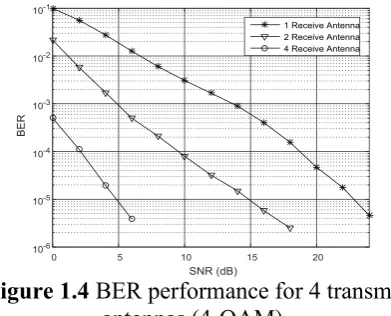
Figure 1.4 BER performance for 4 transmit antennas (4-QAM).
Fig. 1.4 demonstrates the error performance comparison for four transmit and one, two and four receive antennas using 4-QAM modulation. It can be seen that four receive antenna system is superior than two receive antenna system by
about 9.1 dB at the BER of 10-5.
International Journal of Research (IJR)
e-ISSN: 2348-6848, p- ISSN: 2348-795X Volume 2, Issue 08, August 2015Available at http://internationaljournalofresearch.org
is superior than two receive antenna system by
about 7.9 dB at the BER of 10-4.
Figure 1.5 BER performance for 4 transmit antennas (4-PSK).
b. Transmit Diversity
Here we consider the effect of transmit diversity on the bit error rate performance of the system. Performance is evaluated using 2 and 4 transmit antennas and 1, 2 and 4 receive antennas. The underlying system is considered to be a MIMO systems designed for an underlying 4-QAM and 4-PSK. We assume that the channel exhibits a quasi-static frequency flat Rayleigh fading over the frame duration. We consider a frame size of 100 symbols. We assume perfect CSI is available at the receiver. Decoding of the received symbols is done via PSOGSA algorithm.
The result shows that increasing the number of
transmit antennas yield a significant
performance gain.
Figure 1.6 BER performance for 4 receive antenna (4- QAM).
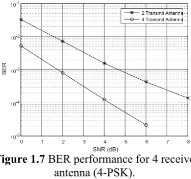
Figure 1.7 BER performance for 4 receive antenna (4-PSK).
Fig. 1.6 demonstrates the error performance comparison for four receive and two and four transmit antennas using 4-QAM modulation. It can be seen that 4 transmit antenna system is superior than two transmit antenna system by
just about 2.2 dB at the BER of 10-5.
Fig. 1.7 demonstrates the error performance comparison for four receive and two and four transmit antennas using 4-PSK modulation. It can be seen that four transmit antenna system is superior than two transmit antenna system by
just about 2.9 dB at the BER of 10-3.
c. Effect of Modulation
International Journal of Research (IJR)
e-ISSN: 2348-6848, p- ISSN: 2348-795X Volume 2, Issue 08, August 2015Available at http://internationaljournalofresearch.org
Figure 1.8 BER performance for 4 transmit antennas.
It can be seen that with QAM modulation the system performs better than the one with PSK modulation for same number of transmit and receive antennas.
Fig. 1.8 demonstrates the error performance comparison for two transmit and one, two and four receive antennas using 4-QAM and 4-PSK modulations. It can be seen that with QAM modulation the system performs better than the one with PSK modulation for same number of transmit and receive antennas.
d. Comparison
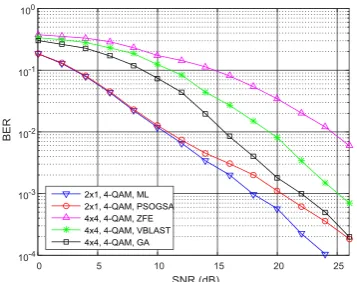
Fig. 1.9 demonstrates the error performance comparison for various techniques with our proposed system using PSOGSA algorithm. It can be seen that the proposed system
Figure 1.9 BER performance comparison. e. Summary
From the above results we can deduce that though the PSOGSA based MIMO decoder is not better than the ML based MIMO decoder,
but provides near optimal results with much lower complexity level as compared to the ML detector. PSOGSA based MIMO detector uses a simple model and has lesser implementation complexity.
ConclusionIn this dissertation, PSOGSA Optimization assisted symbol detection in a spatial multiplexing system is reported. The resistance to being trapped in local minima, convergence to reasonable solution in fewer iterations and exploratory exploitive search approach makes it a suitable candidate for
real-time wireless communications systems.
PSOGSA based MIMO detector uses a simple
model and has lesser implementation
complexity. For larger number of antennas and higher modulation schemes the proposed detector is expected to give near optimal results with much lower complexity level as compared to the ML detector and VBLAST detectors.
References
[1] Y. Chen, H. Halbauer, M. Jeschke and R.
Richter, “An efficient Cholesky
Decomposition based multiuser MIMO
detection algorithm,” in Personal Indoor
and Mobile Radio Communications
(PIMRC), 2010 IEEE 21st International Symposium on, 2010.
[2] O. B. Belkacem, R. Zayani, M. L. Ammari, R. Bouallegue and D. Roviras, “Neural
network equalization for frequency
selective nonlinear MIMO channels,” in Computers and Communications (ISCC), 2012 IEEE Symposium on, 2012.
[3] C.-N. Chuah, D. N. Tse, J. M. Kahn, R. Valenzuela and others, “Capacity scaling in MIMO wireless systems under correlated
fading,” Information Theory, IEEE
Transactions on, vol. 48, no. 3, pp.
637-650, 2002.
[4] X. Tang and Y. Hua, “Optimal design of non-regenerative MIMO wireless relays,”
Wireless Communications, IEEE
Transactions on, vol. 6, no. 4, pp.
International Journal of Research (IJR)
e-ISSN: 2348-6848, p- ISSN: 2348-795X Volume 2, Issue 08, August 2015Available at http://internationaljournalofresearch.org
[5] A. J. Paulraj, D. Gore, R. U. Nabar, H. B{\"o}lcskei and others, “An overview of MIMO communications-a key to gigabit
wireless,” Proceedings of the IEEE, vol.
92, no. 2, pp. 198-218, 2004.
[6] M. Cadik and P. Slavik, “Evaluation of two principal approaches to objective image
quality assessment,” in Information
Visualisation, 2004. IV 2004. Proceedings. Eighth International Conference on, 2004.
[7] R.-R. Chen, R. Peng and B. Farhang-Boroujeny, “Markov Chain Monte Carlo: Applications to MIMO detection and
channel equalization,” in Information
Theory and Applications Workshop, 2009, 2009.
[8] E. Dumic, S. Grgic and M. Grgic, “Improved image quality measure through
particle swarm optimization,” in Systems,
Signals and Image Processing (IWSSIP), 2011 18th International Conference on, 2011.
[9] M. G. E. Schneiders, “Wavelets in control engineering. Master’s thesis,” 2001.
[10] T. Datta, N. A. Kumar, A. Chockalingam and B. S. Rajan, “A novel MCMC algorithm for near-optimal detection in
large-scale uplink mulituser MIMO
systems,” in Information Theory and
Applications Workshop (ITA), 2012, 2012.