ISSN (Print) : 2320 – 3765 ISSN (Online): 2278 – 8875
I
nternational
J
ournal of
A
dvanced
R
esearch in
E
lectrical,
E
lectronics and
I
nstrumentation
E
ngineering
(An ISO 3297: 2007 Certified Organization)
Vol. 4, Issue 4, April 2015
Copyright to IJAREEIE 10.15662/ijareeie.2015.0404074 2153
An Intelligent Control System for Pulverised
Coal Feeder-Real time Approach
Mr.Saju.S
1, Chitra.H
2, Geetha.S
3, Priyanka.A
4Assistant Professor, Dept. of EIE, Saveetha Engineering College, Thandalam, Tamilnadu, India
1UG Student, Dept. of EIE, Saveetha Engineering College, Thandalam, Tamilnadu, India
2,3,4ABSTRACT: Commonly thermal power plants use coal as the main source i.e. fuel for generating power. Continuous level measurement is a critical process in coal-fired power plants. It is essential to measure the level of coal in bunkers that feed the turbines which, in turn, generate electricity. Unreliable levels of coal in the bunkers can potentially interrupt electricity generation and cause disruption in service. There are many techniques for solid level measurement system and we choose load cell based level monitoring. The main advantage of this load cell technique is free maintenance compared to sensors. Inside coal bunker are dusty environment and the sensors are not suitable.
We conclude that the load cell based level monitoring is implementing along with PIC microcontroller interface and we design a simple closed loop for speed control for coal feeding system.
KEYWORDS: Continuous level measurement, load cell, PIC microcontroller, speed control
I.INTRODUCTION
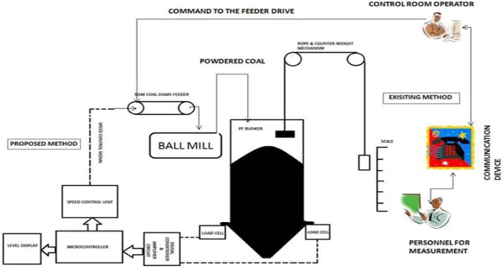
Maintaining a constant supply of coal in the bunkers has proven to be a challenge. In the past, high level mechanical type switches were used for alarm control near the top of the bunkers. Many plants still have operators that make use of a rope and weight to measure the level in the fifty or sixty foot tall bunkers. Many times, the bunkers would run empty of coal, which would cause a disruption/delay in fueling of the burner and leading to electricity delays. Here the coal level is monitored manually by person under the shift. So depending on the coal measured in the bunker the speed of the chain feeder is controlled. Chain feeder speed is controlled by the operator working under shift depending on the measured level of coal inside the bunker. Hence the speed of chain feeder is not a smooth change in variation;it has only two type of speed one is high speed another is the low speed. The existing method might lead to various human errors in measurement of coal. If the measured level is incorrect then it might lead to serious damage to the equipments like fire out, boiler failures etc. In case of incorrect measurement may also lead to trip the entire generation unit which is the major drawback since it might lead to money loss in terms of power loss due to start the generating unit from the OFF condition.
In this system the 3kg capacity load cell is placed under the coal bunker. The excitation input +5V and -5V is given to the load cell using dual power supply circuit. The load cell produces an output voltage in the range of millivolts(mV) with respect to the coal bunker weight. At initial condition the coal bunker weight is zero so the load cell output is also zero, in this status the chain feeder drive of coal will rotate at maximum speed, hence large amount of coal is sent to the ball mill and get pulverized then stored in PF bunker so the weight of the PF bunker is increased.
II.LITERATURE SURVEY
―Low-Cost Undergraduate Control Systems Experiments Using Microcontroller-Based Control of a DC Motor”: ManavaalanGunasekaran and RamprasadPotluri. IEEE Transactions on education,vol. 55,no.4, November 2012.
ISSN (Print) : 2320 – 3765 ISSN (Online): 2278 – 8875
I
nternational
J
ournal of
A
dvanced
R
esearch in
E
lectrical,
E
lectronics and
I
nstrumentation
E
ngineering
(An ISO 3297: 2007 Certified Organization)
Vol. 4, Issue 4, April 2015
Copyright to IJAREEIE 10.15662/ijareeie.2015.0404074 2154
use. The objective of this module is that students—fresh from a first course in control systems theory, which introduces them to proportional-integral-derivative control and to design using Bode plots and root locus.
“Intelligent Instrumentation of Solid Fuel Power Plants”:UrpoKortela and YrjdMajanne Instrumentation and Measurement Technology Conference, 1994. Advanced Technologies in I & M., 1994 IEEE.
Large variations in moisture content and heat value of fuels (peat, bark, coal) can cause stability problems in combustion. Some computer-based methods to improve the measurement and control of solid fuel boilers have been developed. A microprocessor-based four-beam infrared moisture measurement system has been developed, which has advantages compared with ordinary two-beam sensors. The paper also presents a digital measuring station for estimating the fuel power of the plant. Furthermore, flame monitors might give a false "flame-off" indication even if the fuel is still burning. The system developed herein estimates the changes of the combustion process by comparing the amount of flue gases generated in the process with the fuel and air feed. By adding this information to the signals obtained from the flame monitoring system, the existence of the flame can be verified. Finally, load level and combustion conditions in industrial power plants vary continuously, and when solid fuels are used, the optimal excess air in the flue gas does not stay constant. We have developed and tested a method for minimizing the losses of the boiler.
“Pulse-Width Modulation DC Motor Control”, Howard f. Weber ; Instrumentation and Measurement Technology Conference, 1994.
In order to control the speed of a dc series field motor at different required torque levels, it is necessary to adjust the voltage applied to the motor. The common method of varying the speed of the motor is by inserting resistance in series with motor to reduce the supplied power. This type of motor speed control is very inefficient and wasteful of battery power due to the 12R loss, especially under high current, high torque conditions. A much more efficient method of controlling the voltage applied to the motor is the pulse-width modulation method. In this method a variable width pulse of voltage is applied to the motor. A diode is placed in parallel with the inductive motor path to provide a circuit for the inductive motor current when the switch is opened. This circulating current path prevents abrupt current changes and resultant high voltage across the switching device, while allowing more average current to flow through the motor than is taken from the battery.
“8096 Microcontroller Based Field Acceleration Method Control for Induction Motor with New Digital PWM Inverter Technique”: Hao Yun Zhong and A.K Behera, Muhammad H. Rashid
Based on Field Acceleration Method control of an induction motor and a new digital PWM inverter technique, a novel induction motor variable-frequency and variable –voltage drive system is presented. Knowing the slip frequency (sw) and motor speed (w), the amplitude of an induction motor terminal voltage can be calculated using a program, and in turn, the time periods of the PWM inverter can also be determined. The control algorithm has been implemented with an Intel 8096 microcontroller. The experimental results, carried out using a 0.5 HP induction motor, prove the excellent characteristic for speed response, which confirms the validity of this control strategy.
III. COMPONENT DESCRIPTION
PF BUNKER
PF bunker is defined as a Pulverized Fuel bunker, which is a secondary storage of a coal fired power plant. In ETPS the PF bunker has a capacity of 6.5 tonnes/hour and the speed is about 8rpm to 80rpm. It is drived by eddy current drive.
LOAD CELL
ISSN (Print) : 2320 – 3765 ISSN (Online): 2278 – 8875
I
nternational
J
ournal of
A
dvanced
R
esearch in
E
lectrical,
E
lectronics and
I
nstrumentation
E
ngineering
(An ISO 3297: 2007 Certified Organization)
Vol. 4, Issue 4, April 2015
Copyright to IJAREEIE 10.15662/ijareeie.2015.0404074 2155
electrical signal and the strain gauge change the electrical resistance in it. A load cell consists of four strain gauges in wheatstone bridge configuration.
AMPLIFIER CIRCUIT
Amplifier circuit is used for amplifying the output signal from the load cell. Because of the strain gauge deformation, the will be a change in electrical resistance which causes the bridge output to be changed. There by there is a change in output voltage which is directly proportional to the applied force.
PIC MICROCONTROLLER
PIC16F877A is an eight bit microcontroller working with (2V – 5V) dc supply. It has 1000 time write/erase cycle enchanced flash memory.There are five input and output ports , they are port-a, port-b, port-c, port-d and port-e. It is 40 pin IC in QDIP and PFQ package.
LIQUID CRYSTAL DISPLAY
The module that we are using is a 16 character x 2 line display. It uses an ST7065C controller, which is HD44780 compatible. The last 2 pins (15th & 16th) are optional and are only used if the display has a backlight. This display is used for displaying the level of the PF bunker in the power plant.
SPEED CONTROL UNIT
The combinations of optocoupler, MOSFET and micro controller are used as a speed control unit. Hence PWM technique is used for controlling the chain feeder drive.A DC motor is any of a class of electrical machines that converts direct current electrical power into mechanical power. The most common types rely on the forces produced by magnetic fields.
ISSN (Print) : 2320 – 3765 ISSN (Online): 2278 – 8875
I
nternational
J
ournal of
A
dvanced
R
esearch in
E
lectrical,
E
lectronics and
I
nstrumentation
E
ngineering
(An ISO 3297: 2007 Certified Organization)
Vol. 4, Issue 4, April 2015
Copyright to IJAREEIE 10.15662/ijareeie.2015.0404074 2156 IV. HARDWARE MODEL
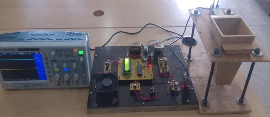
The hardware result is produced by applying pressure or strain on one end of the load cell which is fixed on the top of the pf bunker. The milli volt signals are sent to the instrument amplifier for amplification and then to the analog input in port A of the Micro controller. After processing of the input signal the corresponding level signal as percentage and alarm signal are displayed on the LCD screen. The PWM pulses created by the micro controller is sent to the MOSFET drive by optocoupler and then to the DC Motor which is represented as a fan.
Fig 1.1 Hardware Model
V. SIMULATION AND RESULTS
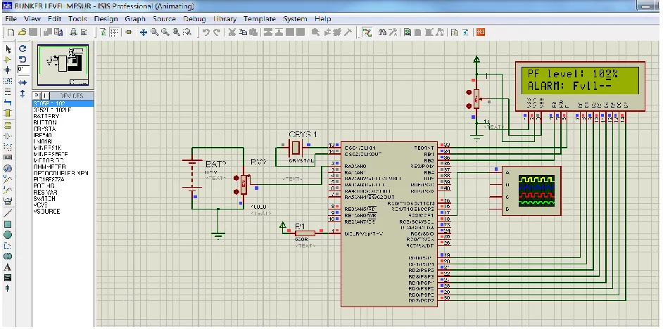
Proteus (PROcessor for TExtEasy to USe) is a fully functional, procedural programming language created in 1998 by Simone Zanella. Proteus incorporates many functions derived from several other languages: C, BASIC, Assembly, Clipper/dBase; it is especially versatile in dealing with strings, having hundreds of dedicated functions; this makes it one of the richest languages for text manipulation. There are four levels assigned for the level of coal in the bunker. Due to safety reasons the four levels empty, low, normal, high are set. The level of coal which is measured by the load cell is displayed in the LCD screen as percentage value along with the corresponding alarm signal. The four levels are:
0-40% empty
40-60% low
60-80% normal
80-99% high
100% and above is full or overflow
ISSN (Print) : 2320 – 3765 ISSN (Online): 2278 – 8875
I
nternational
J
ournal of
A
dvanced
R
esearch in
E
lectrical,
E
lectronics and
I
nstrumentation
E
ngineering
(An ISO 3297: 2007 Certified Organization)
Vol. 4, Issue 4, April 2015
Copyright to IJAREEIE 10.15662/ijareeie.2015.0404074 2157
Fig 1.2 Simulation result for empty level range
ISSN (Print) : 2320 – 3765 ISSN (Online): 2278 – 8875
I
nternational
J
ournal of
A
dvanced
R
esearch in
E
lectrical,
E
lectronics and
I
nstrumentation
E
ngineering
(An ISO 3297: 2007 Certified Organization)
Vol. 4, Issue 4, April 2015
Copyright to IJAREEIE 10.15662/ijareeie.2015.0404074 2158
The voltage signals for the corresponding levels of coal are measured using multimeter and the results are tabulated.
Bunker level
(%)
Isolator Output
(Volts)
MOSFET Output
(Volts)
0 10.18 4.5
25 9.52 5.6
50 8.38 6.7
75 7.20 8.57
Table 1 Hardware result
OSCILLOSCOPE OUTPUT
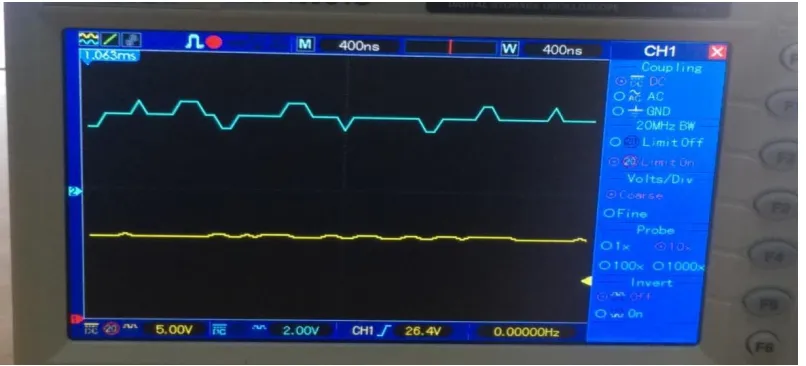
The waveform is similarly captured from the optocoupler output and MOSFET output by connecting a digital Oscilloscope. The fig 1.4 shows the low level range in which the coal is filled correspondingly 4.5-9meters in height of the total 18meter pf bunker.
Fig 1.4 Scope graph for low level (40-60%)
ISSN (Print) : 2320 – 3765 ISSN (Online): 2278 – 8875
I
nternational
J
ournal of
A
dvanced
R
esearch in
E
lectrical,
E
lectronics and
I
nstrumentation
E
ngineering
(An ISO 3297: 2007 Certified Organization)
Vol. 4, Issue 4, April 2015
Copyright to IJAREEIE 10.15662/ijareeie.2015.0404074 2159
Fig 1.5 Scope graph for normal range (60-80%)
The fig 1.6 shows the high level range in which the coal is filled correspondingly 13.5-18 meters in height of the total 18meter pf bunker.
Fig 1.6 Scope graph for high range (80-100%)
VI.CONCLUSION
ISSN (Print) : 2320 – 3765 ISSN (Online): 2278 – 8875
I
nternational
J
ournal of
A
dvanced
R
esearch in
E
lectrical,
E
lectronics and
I
nstrumentation
E
ngineering
(An ISO 3297: 2007 Certified Organization)
Vol. 4, Issue 4, April 2015
Copyright to IJAREEIE 10.15662/ijareeie.2015.0404074 2160
occurring due to boiler fire out are compensated. Simple and low cost techniques used hence complications and skilled labor is not necessary. Since PIC Microcontroller is used it can be easily replaced and maintained.
REFERENCES
[1] Longbottom, F.; Orbital Engines Co., Balcatta, WA, Australia ; Eren, H. ―Ultrasonic multiple-sensor solid level measurements‖Instrumentation and Measurement Technology Conference, 1994.,Vol.2 pg.749-752,1994.
[2] ManavaalanGunasekaran and RamprasadPotluri, Member, IEEE. ―Low-Cost Undergraduate Control Systems Experiments Using Microcontroller-Based Control of a DC Motor‖ IEEE Transactions on education,Vol. 55,Issue no.4, pg.508-516, Nov 2012.
[3] G. C. Goodwin, A. M. Medioli, W. Sher, L. Vlacic, and J. S. Welsh, ―Emulation-based virtual laboratories: A low-cost alternative to physical experiments in control engineering education,‖ IEEE Trans. Educ., Vol. 54, Issue no. 1, pp. 48–55, Feb. 2011.
[4] Kortela,Urpo Tampere University of Technology, Tampere,Finland ―Intelligent instrumentation of solid fuel power plants‖ Instrumentation and Measurement Technology Conference, 1994. Advanced Technologies in I & M., Vol.7 Issue no.4,pg.31-35, 1994 IEEE.