Study on the Parameters Affecting Magnetic
Induction Waveguide for Underground
Communication
Mittu M1 , Lenin Joseph2
Student, Dept of Electronics and Communication, Sree Buddha College Engineering for Women, Elavumthitta ,Pathanamthitta, Kerala,
India1
Assistant Professor, Dept of Electronics and Communication, Sree Buddha College Engineering for Women, Elavumthitta,
Pathanamthitta, Kerala, India2
ABSTRACT:Wireless Communication with in dense substances such as soil or rock is more challenging than through air.
Transmission range for Magnetic induction in Underground communication is too short for practical applications. MI Waveguide technique for communication is developed to reduce pathloss and extend transmission range. This paper deals with the parameters affecting the MI Waveguide for Underground communication.
KEYWORDS:- Underground communication, MI Waveguide.
I. INTRODUCTION
Traditional wireless communication techniques using Electromagnetic wave encounter major problems in soil medium such as small communication range, high path loss, dynamic channel conditions and large antenna size. Due to propagation properties of EM waves, EM communication is recommended only for short range applications. Magnetic induction (MI) is a highly effective physical layer technique for underground wireless communication and under water communication. MI was first introduced to wireless underground communication field and it was observed that the MI transmission is not affected by soil type, composition, compaction or moisture content. The power requirement is also low. The attenuation rate of magnetic fields in dense soil medium is similar to that in the air. However, the experimental communication range attained is not more than 4.5m.
II.MIWAVEGUIDE
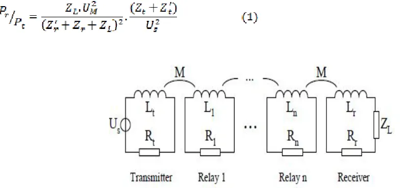
MI Systems operate over short ranges and has constant channel conditions in soil as well as in air. This system is not useful for most of the terrestrial applications due to very high path loss. To enhance the range in practical applications, relay points are employed between the transmitter and the receiver. MI Waveguide is one technique which employs multiple passive relay coils between the transmitter and the receiver. A typical MI Waveguide system is shown in Fig. 1
Fig. 1. MI Waveguide
The magnetic flux created by a time varying current in one relay coil links with its neighbours to induce further sinusoidal currents. This sinusoidal current in the relay coil in turn induce further currents in their neighbours which forms a MI waveguide. The total path loss of MI waveguide can be greatly reduced by appropriately designing the waveguide parameters. These relay coils can be wound along the pipe lines, and once buried, they do not require additional maintenance which makes them easy to deploy. The relay coils are also useful to reduce the overall cost and energy of the system.
III.SYSTEM MODELING
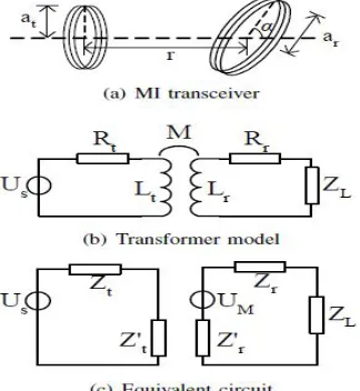
The MI transmitter and receiver can be modelled as the primary coil and the secondary coil of a transformer respectively [2,3], where Mis the mutual induction between the transmitter coil and receiver coil; Usis the voltage of the transmitter’s battery; Lt and Lr are the self-inductions and Rt and Rr are the resistances of the coils; ZL is the load impedance of the receiver. The relationship between the power consumed in the primary loop and the power consumed in the load impedance ZL is shown in equation 1 [3].
Fig. 3. Transformer model of the MI waveguide.
A typical MI waveguide structure is shown in Fig.3, where n relay coils are placed equally spaced along the axis between the transmitter and the receiver; r is the distance between the neighbouring coils; d= (n+1)r is the distance between the transmitter and the receiver and ais the radius of the coils. The path loss MI waveguide can be calculated using equation 2 [3].
From equation 2 it can be observed that the operating frequency and the number of turns of the coils can select suitably to reduce the path loss. Also the loss in received power with distance can be reduced by increasing the number of coils.
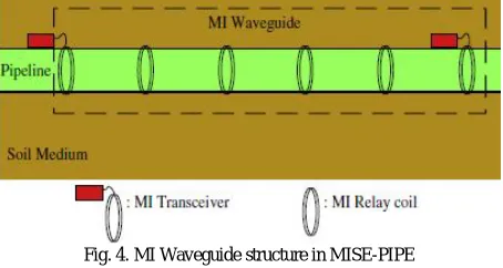
IV. MI WAVEGUIDE IN MISE-PIPE
Fig. 4. MI Waveguide structure in MISE-PIPE
In MI waveguide shown in Fig. 4, n-1 relay coils are deployed between two underground sensor nodes. Each sensor node acts as a MI transceiver. Assuming required bandwidth is B and length of the link is d, the path loss of the MI Waveguide can be derived as shown in equation 3 [1,2,3],
(3)
where M is the mutual induction between the adjacent coils; Z is the self-impedance of relay coil; ζ(Z/Ωm,n) is the n
order polynomial of Z/ωM. When ω=ω0, Z becomes purely resistive R, where ω is the angle frequency of transmitted
signal, ω0 is the centre frequency of the signal and R is the coil wire resistance. The polynomial ζ(x,n) is given by
ζ
The Mutual inductance between the adjacent coils can be given by
M
≈ µᴨ
N
2a
4/2r
3= µ
ᴨ
N
2a
4/2(d/n)
3(6)
where N is the number of turns of wire on the coil and µ is permeability of the pipeline. According to (3), when signal frequency deviates from the central frequency, then path loss increases monotonically. A communication channel is established between the two sensors, if the signal with frequency is correctly received. The frequency is given by
ω=ω0+0.5B.
V. PARAMETERS AFFECTING MI WAVEGUIDE
Some of the parameters affecting the performance of MI waveguide are simulated and analyzed in this section. The different values considered for the simulations are : transmitted power, Pt = 4dBm, operating frequency, ω0 = 10MHz, received power threshold, Pth = -80dBm, bandwidth, B = 1KHz, the angle frequency of the transmitted signal, ω = ω0 + 0.5B, resistance of unit length of the copper wire used, R0 = 0.01Ω/m, Non-metallic pipelines are considered for the simulations.
increases which in turns reduces the path loss. It can be observed that the effective communication range can be increased by increasing the number of relay coils.
Fig. 5. Received power of MI Waveguide with different number of relay coils
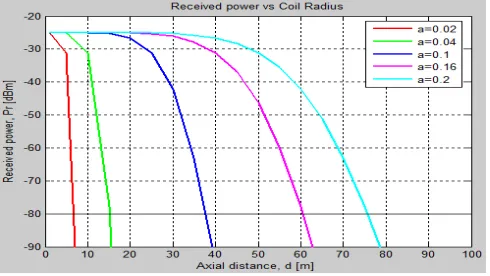
B. Effect of Radius of Relay Coils
The effect of radius of coils on the axial range is shown in Fig. 6. For simulation, the number of coils considered is 10 and number of turns considered is 20. The mutual inductance between the coils is directly proportional to the coil radius and hence the received power also increases with the coil radius. It can be observed that the number of relay coils needed may be reduced by using coils with larger radius.
Fig. 6. Received power Vs Coil radius
C. Effect of Number of turns of Relay Coils
Fig. 7. Received power Vs number of turns
D. Effect of Unequal Spacing of Relay Coils
The mutual inductance between the coils remains constant when the coils are equally spaced. In practical scenario, it is difficult to maintain uniform spacing between the coils. The effect of such variations is shown in Fig.8. The number of coils considered is10, radius of the coil is 0.15 number of turns is 20 and the maximum variation in the spacing is 20 cms. It can be observed that the variations are negligible in the practical scenarios.
Fig. 8. Received power Vs distance for unequal spacing.
E. Effect of Damage of Relay Coils
F. Effect of Metallic Pipe instead of Non-metallic Pipe
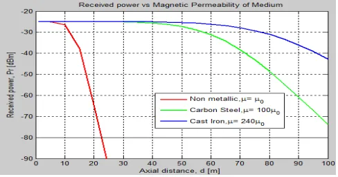
In all the previous simulations, non-metallic pipelines were considered. Pipelines are normally made of non-metallic materials owing to longer life. In MI waveguide, metallic pipelines will have a significant impact, since the metal pipe can act as a magnetic core for the relay coils. The effect of using a metallic pipe is shown in Fig. 10. For simulation, the number of coils considered is 2, radius of the coil is 0.15 and number of turns 20. It can be observed that the effective communication range is increased drastically with metallic pipeline which is due to the increase in the value of µ and hence the mutual inductance. Thus the number of relay coils can be reduced by the use of metal pipelines as they act as a perfect core for the magnetic induction system.
Fig. 10. Received power Vs Magnetic Permeability of medium
VI.CONCLUSION
In this paper, some of the parameters affecting MI waveguide has been simulated and studied. The effective range of MI waveguide channel is directly proportional to the number of relay coils, radius of the coils and the number of turns of the coil. The effective range of MI communication can be enhanced from less than 5m to 90m using MI waveguide technique by employing nearly 20 relay coils which does not add much cost to the system. Some small variations in the spacing between the coils do not have any significant impact on the effectiveness of the system, which makes it easier to deploy. The damage to the relay coils has a considerable impact of the system which makes it necessary to consider the practical deployment scenario for calculating the optimal number of relay coils. Overall MI waveguide looks a promising technique for short distance underground communications with lower data rates.
REFERENCES
[1] Zhi Sun , Pu Wang, Mehmet C. Vuran, Mznah A. Al-Rodhaan, Abdullah M. Al-Dhelaan , Lan F. Akyildiz “ Magnetic induction-based wireless sensor networks for underground pipeline monitoring ”, IEEE journal on Ad Hoc Networks, vol.9, 2011
[2] Z. Sun, I.F. Akyildiz, Magnetic induction communications for wireless underground sensor networks, IEEE Transactions on Antenna and Propagation 58 (7) (2010) 2426–2435