138 | P a g e
STUDY OF VAPOUR COMPRESSION
REFRIGERATION SYSTEM USING DOUBLE PIPE
HEAT EXCHANGER
Rakesh R
1, Manjunath H N
2, Madhusudhan
31
M.Tech (MTP) Student,
2Assistant Professor,
3Professor, Department of Mechanical Engineering,
Nitte Meenakshi Institute of Technology Bengalur,
Affiliated to Visvsevaraya Technological University Belagavi, Karnataka(India)
ABSTRACT
The enhancement of Coefficient of Performance (COP) is obtained by diminishing the compressor work and
expanding the Refrigerating impact. With the refrigerant R134a (Tetra Fluro Ethane),VCR (vapor pressure
refrigeration) framework is experimentally examination and the results were recorded. The fixed mass flow of
refrigerant,suction and deliverypressure of compressor, condenser and evaporator temperature are the impacts
of the fundamental parameters of execution for investigation. The readings from VCR are noted down with the
variables like pressure at compressor inlet, pressure at compressor outlet, temperatures at condenser and
evaporator inlet and outlet and COP was figured. The outcomes got will be approved through CFD. Further the
COP is improved by sub-cooling the refrigerant at condenser outlet with double pipe heat exchanger. The
upgrade will be approved through CFD; by designing inCreo 2.0, examination in FLUENT and CFD POST for
post results.
Keywords: VCR, Double Pipe Heat Exchanger, Refrigeration, Sub-Cooling
I.
INTRODUCTION
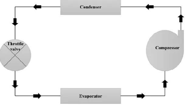
139 | P a g e refrigeration framework comprises of primary four parts which are compressor, condenser, expansion valve, and evaporator. A low temperature and low pressure refrigerant is compressed in compressor from the evaporator to high temperature and high pressure. After the compression the refrigerant is let out into the condenser,where the buildup procedure involves heat dismissal to the environment. The refrigerant will be condensed at climatic temperature by expanding the refrigerant's temperature and pressure over the environmental temperature. After the buildup procedure, the refrigerantwhich is high pressure is made to flow into the extension valve, here the refrigerant temperature is dropped below the temperature ofsurrounding by loweringthe pressure in the
expansion valve. As the pressure isdropped, vapour refrigerantexpands. When vapourexpands, it pulls the energy from the medium in which it is contact or the surroundings and along these lines gives out refrigeration impact to its environment. After this procedure, the refrigerant is prepared to drawn heat from the space where it should be refrigerated. The heat ingestion procedure will be done in the evaporator. The heat ingestion procedure is ordinarily known as an evaporation procedure. The cycle is completed when refrigerant comes back in to the compressor before suction line and after evaporation process.
An ejector-vapor compression refrigeration cycle is built up,which utilized an intercooler and an inside heat exchangerto improve execution of the cycle. Theacquired resultsdemonstrated that, there is an expansion of 8.15% in second law effectiveness and 8.6% in coefficient of execution values separately to that of new ejector-vapor compression refrigeration cycle when contrasted with routine ejector-ejector-vapor compression refrigeration cycle, (refrigerant R125). It has been likewise found that there was 21%expansion inthe COP to that of new ejector-vapor compression cycle in contrast with the routine vapor compression framework[1]. The examination of an ejector with environment benevolent refrigerants is done, where in vapor ejector refrigeration is a heat operated framework using poor quality energy, for example, sun based energy, heat wasted from industrial plants, and so forth., and it can worked effectuality at generator temperature as lower as 6500C.The resultsacquired demonstrates that, among the working liquids chose, R134a refrigerantgave a superior execution
140 | P a g e and higher critical entrainment proportion in correlation with various other refrigerants[2]. Therefrigeration framework is built, which consolidates an essential vapor compression refrigeration system with an ejector cooling cycle. Here wastedrives the ejector cooling cycle i.e., the heat which is dissipated from the condenser in VCR cycle. Extra cooling is limit from theejector cycle is specifically enter into the evaporator of the VCR cycle.The frameworkinvestigation demonstrates that this refrigeration framework can viably enhance the COP with refrigerant having high temperature at compressor outlet by the ejector cycle[3].
The condition of the refrigerant which is entering the throttling valve of traditional vapor compression refrigeration cycles is generally thought to be saturatedliquid. As theliquid is cooledbelow saturated liquid the throttling is reduced and hence COP is increased. Subcooled refrigerant before expansion procedure can be acquired by including additional segments, for example, internalheat exchangers in single-stage cycles [4] and in two-stage cycles. Sub-cooling can likewise be accomplished by assistant cooling framework, for example, a thermoelectric device[5], an optional vapor compression framework – otherwise called mechanical sub-cooling [6]or utilizing accessible coolant supplies, for example, condensate water from evaporator[7]
II.
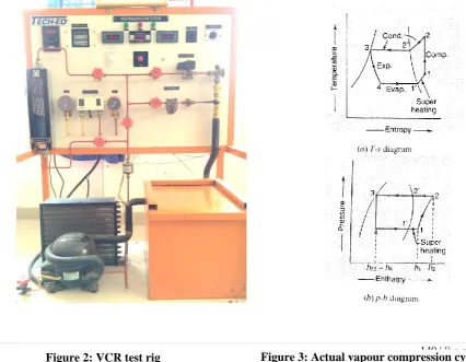
EXPIREMENTATION
The experiment is carried on the VCR system with the 0.01m refrigerant pipe diameter having the compressor and condenser capacity of 1/3 HP with energy meter 2.5 to 5 amps. It is observed that the compressor inlet temperature T1is 8
0
C and coming out with the temperature of T260 0
C, temperature at outlet of condenser outletT3is found to be 300C finally temperature T4 at the inlet to theevaporator is 00C. Now P1and P2 are
141 | P a g e upstream and downstream pressure of the Compressor in bar (8.89 and 1.93). The refrigerant used in this system is R134a (Tetra Fluoro Ethane)
Coefficient of Performance = =
C.O.P = 2.151
The C.O.P of actual vapour compression cycle is found to be 2.151 and it also noted that the refrigerant is slightly super-heated before compression. The calculated values of heat flux at condenser coil and evaporator coil is found to be 13701.46 W/m2 and 3456.46 W/m2
III.
VALIDATING THE EXPERIMENTAL RESULTS IT IN ANSYS FLUENT
The geometry is modeled in Creo 2.0 and imported into ANSYS 15 which is saved in .iges format. Evaporator coil having the 10mm diameter pipe and 12.5 turns with 20mm pitch and 200mm coil diameter. Condenser coil has 24 number of coils with 0.3m length and 20mm pitch. Solution is setup with scheme of SIMPLE, in discretization methods Green gause node base, for pressure second order discretization form and second order upwind for energy and momentum. Results obtained with ANSYS FLUENT matches with the experimental values.
IV.
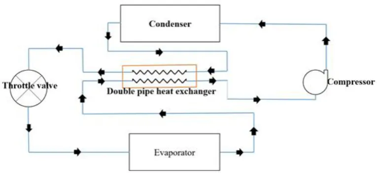
MODIFIED VCR SYSTEM
The existing refrigeration system is modified by incorporating the double pipe heat exchanger in between condenser and expansion valve in inner tube with that of counter flow outer tube in between evaporator and compressor, D1 = 0.011m and D2 = 0.015m at annulus D = 0.01m at the tubs side, in which temperature is
Figure 2: Modified VCR system
142 | P a g e
Figure 5: Magnified image of double pipe heat
exchanger
It is found that the total heat transfer in double pipe heat exchanger is found to be 45.76 W, overall heat transfer is 61.97W/m2K. The calculated length for this double pipe heat exchanger is 1.1256m. Now to find the compressor outlet temperature polytropic index is calculated and found to be 1.125 and the temperature is found to be
Coefficient of Performance = =
C.O.P = 4.139
V.
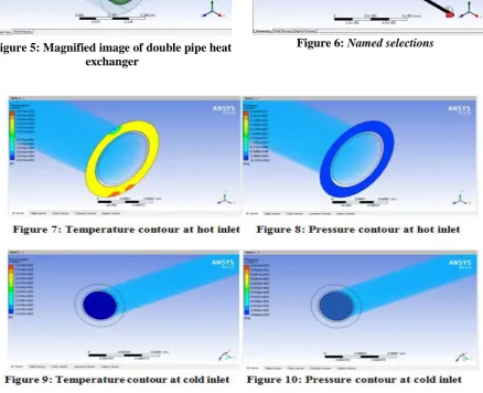
VALIDATINGTHE MODIFIED VCR(DOUBLE PIPE HEAT EXCHANGER) IN
ANSYS FLUENT
143 | P a g e
VI.
CONCLUSION
COP of existing Vapour Compression Refrigeration system is observed to be 2.151.
Evaporator and condenser coil information acquired from investigation is approve in ANSYS FLUENT.
The double pipe heat exchanger length between condenser outlet and evaporator outlet is observed to be 1.1256 m, and the COP for the same is 4.139.
The theoretical results has been approved for the same double pipe heat exchanger between condenser outlet and evaporator outlet in ANSYS FLUENT.
144 | P a g e
REFERENCES
[1] M. S. M Yari, "Performance analysis of the ejector vapour compression refregeration cycle," Journal of power and energy, vol. 221, no. 8, pp. 1089-1098, December 1, 2007.
[2] A. M. A Selvaraju, "Analysis of an ejector with environment friendly refregerents," Applied Thermal Engineering, vol. 24, no. 5, pp. 1-12, April 2004.
[3] Y. Z. a. P. Jiang, "Hybrid vapor compression refrigeration system with an integrated ejector cooling cycle,"
International journal of refrigeration, vol. 35, no. 1, pp. 68-78, January 2012.
[4] D. D. A. Domanski P A, "Evaluation of suction-line/liquid-line heat exchange in the refrigeration cycle,"
International Journal of Refrigeration, vol. 17, no. 7, pp. 487-493, 1994.
[5] Y. B. H. Y. Radermacher R, "Integrating Alternative And Conventional Cooling Technologies," ASHRAE Journal, vol. 49, no. 10, pp. 28-35, October 2007.
[6] L. M. W. S. M. H. Couvillion R J, "Analysis of a vapo-compression refrigeration system with," ASHRAE Transactions, pp. 641-659, 1988.