Comparison between Conventional P & O and
Drift Free P & O MPPT Algorithm for PV
System
Anooja Shahul1, Reenu George2, Emmaneul Babu3
PG Scholar, Dept. of EEE, Mar Athanasius College of Engineering, Kothamangalam, Kerala, India1
Assistant Professor, Dept. of EEE, Mar Athanasius College of Engineering,Kothamangalam, Kerala, India2,3
ABSTRACT: Photovoltaic systems are becoming popular among the renewable energy sources, because of the advantages like lower noise, lesser maintenance etc. The efficiency of a PV system depends on the MPPT module included in the system. P & O algorithm is a simple algorithm which has been used in many systems. Conventional P & O method suffers from a drift problem which occurs due to lack of knowledge, whether the power of PV system increased due increase in insolation or due to the perturbation. In this paper, a modified version of simple P & O method is studied and compared with the conventional P & O algorithm. Drift free method is developed by considering an additional parameter ΔI along with ΔP and ΔV. Both the algorithms are simulated using MATLAB/SIMULINK by incorporating SEPIC converter as an interface between PV system and load side.
KEYWORDS: Insolation, MPPT (Maximum Power Point Tracking), P & O (Perturb & Observe), PV (Photo Voltaic) system.
I. INTRODUCTION
Due to the severity of the environmental pollution and global energy crisis, solar energy has been evolving as the most used renewable energy sources due to its eco-friendly nature, maintenance free, and abundant source of energy. However, the PV systems suffer from big cost of equipment installation and low efficiency. The V-I characteristic of PV system depends on solar irradiance and cell temperature. PV systems efficiency depends on operating point on the P-V characteristics of the module [2]. PV system operates with maximum efficiency and produces its maximum output power at a unique operating point, called the Maximum Power Point (MPP). Therefore, in order to operate PV system at its maximum efficiency, any of the MPPT techniques must be included. Until now a large number of MPPT techniques have been developed to increase the efficiency of the PV system. Here we are focusing on P & O algorithm which is simple and less complex among the others. Even though P & O has many advantages, the sudden change in atmospheric conditions causes this P & O algorithm to drift away from MPP. This paper presents a clear analysis of drift in case of one time insolation change as a sudden phenomenon. Even though the solution to drift problem is given in many previous literatures [3], [4], most of the methods are not effective. And effective method may found impractical. So a new method is used by slightly modifying simple P & O algorithm in case of fast environmental conditions
.
II.CONVENTIONAL P & O ALGORITHM
oscillations, but results in slower response [1]. On the other hand large perturbation step size increases the steady state oscillations [1]. To improve the performance of P & O, a variable perturbation step size can be utilized.
A DC-DC converter acts as an interface to operate at MPP by changing the duty cycle (D) of the converter. In this study, SEPIC converter is considered to validate the proposed drift free P & O MPPT algorithm and it can be applicable to any other converter topology. A DC-DC converter acts as an interface between the PV module and load to operate at MPP by changing the duty cycle of the converter generated by the MPPT controller and a general block diagram of PV system is shown in fig.1.
Fig. 1: Block diagram of PV system Fig. 2: P-V Characteristics
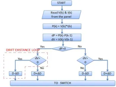
From the P-V characteristics shown in Fig. 2 it is observed that the slope is positive on the left of MPP and negative on the right of MPP. Depending on the sign of the slope, the duty cycle has to be perturbed in order to track the peak power and flowchart of this conventional P & O MPPT algorithm is shown in fig. 3. The duty cycle and the PV voltage (VPV ) are inversely proportional to each other i.e., increase in duty cycle causes the VPV to decrease and vice versa.
Fig. 3: Flow chart of conventional P&O algorithm
A. THREE POINT LEVEL OPERATION
B. DRIFT ANALYSIS
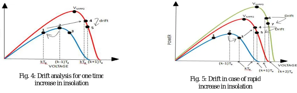
Drift problem occurs for an increase in insolation and it will be severe for a rapid increase in insolation which generally occurs in cloudy days. Drift can occur from any of the three steady state points as shown in fig. 4 and fig. 5 depending on the instant of change in insolation in between the perturbation time (Ta) interval. Drift problem is due to the lack of knowledge in knowing whether the increase in power (dP> 0) is due to perturbation or due to increase in insolation. Suppose there is an increase in insolation while operating at point 1 as shown in fig. 4, then the operating point will be settled to a new point 4 in corresponding insolation curve during the same kTa perturbation interval. Now at point 4 as dP = P4(kTa) - P2((k - 1)Ta) >0 and dV =V4(kTa) - V2((k-1)Ta) > 0 the algorithm decreases the duty cycle and thereby moving to point 5 away from the MPP in the new curve which is called drift. Similarly for an increase in insolation at point 2 and point 3, the drift problem occurs due to confusion of this conventional P & O MPPT technique. This drift problem will be severe in case of rapid increase in insolation as shown in fig. 5.
III. DRIFT FREE P & O ALGORITHM
The conventional P & O MPPT is developed based on the observation of dP and dV by considering the P - V characteristics of the PV module. As already mentioned P & O has a demerit of drift in case of a rapid increase in insolation due to lack of knowledge and this problem can be eliminated by evaluating another parameter dI (change in current). The change in operating point on I - V characteristics due to change in insolation is described below. Relations of VPV and IPV is given below [1],
= , ∆
( )
> 0 (1)
=
( )
, ∆
( )
> 0 (2)
The temperature variation is proportional to the change in insolation i.e., dT/dG> 0. In equation (1) and (2) the numerator is of positive value as Isc,n, KI, ΔT and dT/dG all are positive and the denominator is also of positive quantity as the value of Rsh is larger and Rs is smaller. Thus, conditions dVPV /dG>0 and dIPV /dG> 0 are valid. Hence from equation (1) and (2) it can be noticed that for an increase in insolation both VPV and IPV increase. Thus, with the information of ΔV and ΔI the drift phenomena can be avoided by detecting the increase in insolation.
Fig. 4: Drift analysis for one time
A. DRIFT FREE ANALYSIS
The I-V characteristics of the PV module and the change in operating point due to increase in insolation is shown in fig. 6. As shown in fig. 6 suppose there is an increase in insolation while operating at point 3, then the operating point will settle to a new point 4 in the new insolation curve. Now the decision has to be taken by the algorithm at point 4, where dI=I4(kTa)- I2((k-1)Ta) > 0 as shown fig. 6. At the same time on the P - V characteristics at point 4, both dP = P4(kTa)
-P2((k-1)Ta) > 0 and dV = V4(kTa)- V2((k-1)Ta) > 0 as shown in fig. 7. Thus, all three parameters dP, dV and dI are positive at point 4 as shown in fig. 6 and fig. 7. Thus, the positive value of dP is due to whether perturbation or due to increase in insolation can be detected by using the additional parameter dI. From the I-V characteristics it can be observed that the two parameters both dV and dI can never have the same sign for a single insolation. Both dV and dI will be positive only for an increase in insolation as shown in fig. 6.
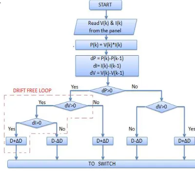
Thus, an increase in insolation can be detected by using the additional parameter dI and thereby increasing the duty cycle (decreasing the operating voltage) where both dV as well as dI are positive can eliminate the drift problem by moving the operating point closer to the MPP as shown in fig. 7. Similarly for an increase in insolation at point 1 and at point 2 the drift problem can be solved by incorporating dI into the algorithm and the movement of operating point with the proposed drift free modified P & O MPPT technique in case of a rapid increase in insolation is shown in fig. 8. The flowchart of this drift free modified P & O MPPT technique is shown in fig. 9.
Fig. 6: I-V Characteristics Fig. 7: Drift free analysis
Fig. 8 : Drift free analysis Fig. 9: Flow chart of drift free P&O
IV. SIMULATION RESULT
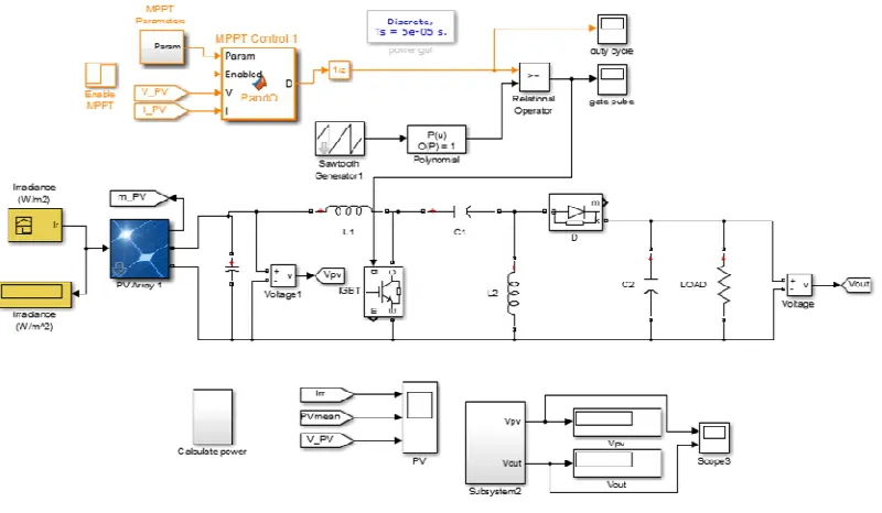
In this simulation work, both conventional P & O and modified P & O are simulated by using MATLAB/SIMULINK 2014. Both the algorithms are compared using simulation results. MPPT parameters are Dint = 0.5, Dmin= 0.42, Dmax= 0.54, ΔD = 3×10⁻⁴.SIMULINK model of the system is shown fig. 10. MPPT algorithm which controls the PV output is programmed in a MATLAB function. Input to the PV system i.e., irradiance is selected as a variable signal. Tracking of maximum power with varying irradiance is analyzed with both algorithms.
VI. COMPARATIVE STUDY
Both the MPPT algorithm has been tested for a step change in insolation level from 250 W/m2 to 1000 W/m2. It can be see that, tracking power is increased in drift free method compared to the conventional P & O method. Simulated graphs are shown in fig. 11, fig. 12, fig. 13. When both methods are compared, at the instant 0.32s, where the change in insolation occurs, power is improved by 16.66%. Current at this instant increases by 12.5% and voltage decreases by 2.5%.
Fig. 13: PV Power
IV.CONCLUSION
In this paper, the drift phenomena for widely used P & O MPPT algorithm are analyzed and then a modification to the existing algorithm is proposed to avoid the drift. The basic principle of the algorithm is to check an extra condition (ΔI) in the traditional P & O algorithm to avoid the drift and the mathematical justification of checking this extra condition is also proved. The simulation result proves that the drift free modified P & O MPPT technique is free from drift and is accurate in tracking the maximum power from the PV panel. The proposed algorithm improves the efficiency of the PV system by gaining the extra power during drift compared to the conventional P & O algorithm. Considerable amount of energy gain can be achieved over the life cycle of the PV panel by using the modified method.
REFERENCES
[1] Muralidhar Killi, Susovon Samanta, “Modified Perturb and Observe MPPT Algorithm for Drift Avoidance in Photovoltaic Systems”, IEEE Transactions on Industrial Electronics, Vol. 62, No. 9, September 2015.
[2] Ahmed M. Atallah, Almoataz Y. Abdelaziz, and Raihan S. Jumaah, “Implementation Of Perturb And Observe MPPT Of PV System With Direct Control Method Using Buck And Buck-boost Converters”, Emerging Trends in Electrical, Electronics & Instrumentation Engineering: An international Journal, Vol. 42, No. 6, May 2014.
[3] Nicola Femia, Giovanni Petrone, Giovanni Spagnuolo, and Massimo Vitelli, “Optimization of Perturb and Observe Maximum Power Point Tracking Method”, IEEE Transactions on Power Electronics, Vol. 20, No. 4, July 2005.
[4] Ashish Pandey, Nivedita Dasgupta, and Ashok Kumar Mukerjee, “High-Performance Algorithms for Drift Avoidance and Fast Tracking in Solar MPPT System”, IEEE Transactions on Energy Conversion, Vol. 23, No. 2, June 2008.
[5] Dezso Sera, Remus Teodorescu, Jochen Hantschel, and Michael Knoll, “Optimized Maximum Power Point Tracker for Fast-Changing Environmental Conditions”, IEEE Transactions On Industrial Electronics, Vol. 55, No. 7, July 2008.
[6] Jitendra Bikaneria, Surya Prakash Joshi, “Modelling and Simulation of PV Cell Based on Two-Diode Model”, Int. J. of Recent Trends in Engineering & Technology, Vol. 11, June 2014 .
[7] Akhilesh P. Patil, Rambabu A. Vatti, “Simulation of Wind Solar Hybrid Systems Using PSIM”, IJETEE,Vol. 10, Issue. 3, April-2014. [8] Srushti R. Chafle, Uttam B. Vaidya, “Incremental Conductance MPPT Technique FOR PV System”, IJAREEIE, Vol.2, Issue6, June2013 [10] Merwan Saad Saoud, Hadj Ahmed Abbassi, “Improved Incremental Conductance Method for Maximum Power Point Tracking using Cuk Converter”, WSEAS Transactions on Power Systems, Issue 3, Volume 8, July 2013 .
[9] Stefan Moring, Anton Pols, “Maximum Power Point Tracking: Algorithm and Software Development”, Int. J. of Recent Trends in Engineering & Technology, Vol. 11, June 2014 .
[10] Ram Naresh, Bharti,Rajib, Kumar Mandal, “Modeling and Simulation of Maximum Power Point Tracking for Solar PV System using Perturb and Observe Algorithm”, IJERA, Vol. 2, Issue 2,Mar-Apr 2012, pp.1420-1424 .
[11] Saurav Satpathy, “Photovoltaic Power Control using MPPT and Boost Converter”, IEEE Transactions on Power Electronics, Vol. 20, No., July 2005.