Implementation of Intercommunication System
using Communication Protocol in Automobiles
Ungarala Satya Rama Manikanta
1& K. Rajasekhar
21
M.Tech Student, Dept. of ECE, Akula Sree Ramulu Institute of Technology, Andhra Pradesh, India
2 Assistant Professor, Dept. of ECE, Akula Sree Ramulu Institute of Technology, Andhra Pradesh, India
ABSTRACT: In trendy fact in which technology has made attractive advances so have the past due automobiles. These cars are greater modern than another time in current memory. They have extra speed, slicing side motors and are excessive due to those motives there's a need to modify a device that can constantly screen all the exceptional parameters of auto. So the utilizing CAN transport (Controller Area Network) which is extensively applied as a part of various fields of industry and particular in the vehicle commercial enterprise, which allow the investigation of statistics going via the delivery and era of messages. In this way the making use of CAN transporting outlining various correspondence (entomb or intra) which is inside the automobile and
inside the middle of automobiles. Here, a protocol
which avoids vehicle accidents is discussed. The vehicle state information is being obtained, using ultrasonic sensors, to predict potential accident and accordingly, reduces the vehicle speed. This protocol provides warning message when the distance is reduces than the safety limit.
IndexTerms: Anti-Collision System, Braking System, Sensor, Communication Protocol.
I. INTRODUCTION
According to a report put together by National Institute of Disaster Management, in India like clockwork there is a street mischance i.e. l080 mischances every day. Human mistakes add up to 93 % of all mischances and as indicated by police, backside impact, passing the main vehicle and not understanding about right or left side moving vehicle constitute 80% of every lethal mishap. STRADA (Swedish Traffic Accident Data Acquisition) performed an examination that shows 9l% of all backsides impacts and surpass crash include trucks [1]. The most well-known backside crash and passing the main vehicle is an impact where an auto's back is smashed by an overwhelming truck. Likewise more impacts that include backside crash do happen without trying to hide with great preservability conditions on a straight street and in
II. RELATED WORK
Controller area network (CAN) provide high reliability and good real-time performance with very low cost. Due to this, CAN is widely used in a wide range of applications, such as in-vehicle communication, automated manufacturing and distributed process control environments.CAN bus is a serial data communication protocol invented by German BOSCH Corporation in 1983. CAN is a network protocol which is designed for the car industry [1].
Since data communication in car often have many sensors transmitting small data packets, CAN supports data frames with sizes only up to 8 bytesas shown in Figure 1. Meanwhile, the 8 bytes will not take the bus for a long time, so it ensures real-time communication. CAN use a large amount of overhead, which combined with a 15-bit CRC makes CAN very secure and reliable. CAN protocol use non-destructive bitwise arbitration process to access shared resource. CAN protocol define a logic bit 0 as a dominant bit and a logic bit 1 as a recessive bit, each. transmitting node monitors the bus state and compares the received bit with the transmitted bit [2]. If a dominant bit is received when a recessive bit is transmitted then the node stops transmitting (i.e. it lost arbitration).
Arbitration is performed during the transmission of the identifier field. There are two message formats: Base frame format with 11 identifier bits and extended frame format with 29 identifier bits [3].
Figure 1. CAN Data Frame
A. CAN Bus Electrical Characteristics
CAN transmission medium formed by the two, One is called high-level transmission line CANH and another is called low-level transmission line CANL, connected to CANH and CANL pins of MCP2551 CAN transceiver. VCANH and VCANL be the voltage level of CANH and CANL lines with respect to ground. The difference between them is called difference voltage Vdiff.
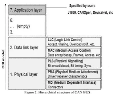
B. Hierarchical structure of CAN BUS
Architecture of CAN protocol based on OSI reference model is as shown in Figure 2. CAN protocol contain only three layers, physical layer, data link layer and application layer. Application layer has different protocols such as SAE J1939, CANopen, DeviceNet, etc [4].
C. Scheduling of CAN BUS
CAN protocol implements fixed priority scheduling of CAN messages. Higher priority node has lower node ID. If available bandwidth is scarce, problems come with traditional fixed-priority based scheduling [5]. It is possible that low priority control loops cannot access the network all the time, since limited resources have been consumed by high priority loops. As a result of tremendous delays, low priority control loops may be destabilized. The problem of fixed priority is overcome using direct feedback scheduling algorithm, namely MUF (maximum urgency first) is integrated in the network scheduler.
Upon invocation, the scheduler calculates the urgency of each control loop based on the set points and current system outputs. According to the MUF algorithm, the scheduler produces new priorities based on these urgency values. And then, messages in different loops will be transmitted in accordance with the newly assigned priorities[6]. A new mixed traffic schedule (MTS) is based on the communication principle of controller area network, network scheduling and analysis of schedule. The core idea of MTS is set the relative deadline information into the identifier. Use the earliest deadline first (EDF) message scheduling algorithm for high priority information and the RMS (rate monotonic scheduling) message scheduling algorithm for low priority information.
D. Reliability
error counter (TEC) and the receive error counter (REC) are started to diagnose the conditions of CAN controller [7]. MCP2515 CAN controller has TEC and REC which enhances reliability of CAN bus system. A CAN controller can be in one of three states: error active, error passive or bus off state. The operating state of the controller is controlled by two error counters – TEC and REC. The CAN controller is in error active state if TEC less than 127 and REC less than 127 [8]. Passive state is used if (TEC greater than 127 or REC greater than 127) and TEC less than 255. Bus off state is entered if TEC is greater than 255. Once the CAN controller has entered bus off state, it must be reset by the host microcontroller in order to be able to continue operation.
III. PROPOSED FRAMEWORK
Following Fig.1 show the system architecture block diagram including the lpc 2148 processor based development board, MCP2515 CAN controller, Ultrasonic Sensor and motor controlling Door (motor driving card), LCD and related hardware.
(a)
(b)
Fig.1 (a) Transmitter (b) Receiver unit of System architecture block diagram
A dominant state occurs when the differential voltage between CANH and CANL is greater than a defined voltage (e.g., 1.2V). A recessive state occurs when the differential
F. Microcontroller
ARM7 Microcontroller: The LPC2148 microcontroller is based on a 32/16 bit ARM7TDMI-S CPU with realtime emulation and embedded trace support, that combines the microcontroller with embedded high speed flash memory ranging from 32kB to 512kB. A 128-bit wide memory interface and a unique accelerator architecture enable
32-bit code execution at the maximum clock rate. For critical code size applications, the alternative 16-bit Thumb mode reduces code by more than 30% with minimal performance penalty. The System Control Block includes several system features and control registers for a number of functions that are not related to specific peripheral devices. These include the Crystal Oscillator, External Interrupt Inputs, Miscellaneous System Controls and Status, Memory Mapping Control, PLL (Phase Locked Loop), Power Control, Reset, VPB Divider, Wakeup Timer. Each type of function has its own register(s) if any are required and unneeded bits are defined as reserved in order to allow future expansion. Unrelated functions never share the same register addresses.
The microcontroller will increase/decrease DC speed via Pulse width modulation. The microcontroller will increase or decrease the ON time and OFF time of the entire pulse time. If we decrease the ON time then the voltage applied to the DC motor will reduce and the speed of the DC motor will be reduced.
Ultrasonic Sensor: Ultrasonic sensors are basically used to measure the distances between the obstacle / object and the sensor. The ultrasonic sensor works on Doppler Effect. It consists of a ultrasonic transmitter and a receiver. The transmitter transmits the signal in one direction. This transmitted signal is then reflected back by the obstacle and received by the receiver. So the total time taken by the signal to get transmitted and to received back will be used to calculate the distance between the ultrasonic sensor and the obstacle. In the present model four Emergency keys are included. Actually these keys may represent ambulance service, brake fail, emergency and addresses respectively.
IV. RESULTS AND DISCUSSIONS
Algorithm for the proposed system is divided in two parts as follows: Transmitter and Receiver
A. Transmitter
Algorithm for transmitter side which consists sensors, AVR microcontroller and CAN (MCP2515) is as follows: 1. Initialize SPI (Serial Peripheral Interface).
2. Initialize LCD.
3. Initialize CAN (MCP2515).
4. Provide impulse to ultrasonic sensor.
5. Measure distance from other car and display on LCD. 6. Transmit distance via CAN (MCP2515).
7. If lane cutting detected send Y else go to step 8. 8. Sense speed and if speed goes beyond range send Z else go to step 9.
B. Receiver
Algorithm for transmitter side which consists output devices, AVR microcontroller and CAN (MCP2515) is as follows:
1. Initialize SPI (Serial Peripheral Interface). 2 . Initialize LCD.
3 . Initialize CAN (MCP2515).
4 . Send acknowledgment to the transmitter.
5. Receive distance data from CAN of transmitter and if distance is less then display warning signal on LCD. 6. If X is received then display “Car cannot be started” else go to step 7.
7. If Y is received then display “Wrong” else go to step 8. 8. If Z is received then turn on buzzer else go to step 9. 9. If A is detected then send data to webpage through LAN else go to step
V. CONCLUSION
Here, the car is equipped with an ultrasonic sensor, which will continuously tracks for any obstacles from the front side. If the obstacle is detected, then the microcontroller will continuously compare the distance given by the ultrasonic sensor. If the distance goes on reducing indicating that, the front car is coming closer to the current car then the microcontroller program will start reducing the speed until the distance is within safe limit.
REFERENCES
[1] MaziarNekovee, “Quantifying Performance Requirements of Vehicle-to-Vehicle Communication Protocols for Rear-end Collision Avoidance”, IEEE 69th, Vehicular Technology Conference, 2009. VTC Spring 2009,page no. 1-5, 2009 IEEE.
[2] Takeshi Kasuga, Satoshi Yakubo, “Design of a Highly Safe Model Vehicle for Rear-End Collision Avoidance Considering Multiple Faults of Sensors”, International Conference on Computational Intelligence, Modelling and Simulation, page no. 63-68,2009 IEEE.
[3] Ding Shiqing, Song Yandong, Ding Jibin, “The Research for Mechanism of Vehicle Rear end Collision Avoidance System”, International Conference on Intelligent Computation Technology and Automation, page no. 889-892, 2010 IEEE.
[4] A. Farahani , G. Latif-Shabgahi, F.Tajarrod, “On the Priority Problem of CAN Protocol: A New Idea”, Education Technology and Computer (ICETC), 2010 2nd International Conference on, page no. V2.500-V2.505, 2010 IEEE.
[5] Huang Zhu, Gurdip Singh, “A Communication Protocol for a Vehicle Collision Warning System”, IEEE/ACM International Conference on Green Computing and Communications & 2010 IEEE/ACM International Conference on Cyber, Physical and Social Computing, Pages: 636 – 644, 2010 IEEE.
[6] Meng Chen, Fasheng Liu, ChuanxiangRen, ZhiminGao, “A Control System of Vehicle Rear-end Anti-collision”, Intelligent Human-Machine Systems and Cybernetics (IHMSC), 2012 4th International Conference on, Pages: 46 – 48, 2012 IEEE.
[7] Adrian Cabrera, Sven Gowal and AlcherioMartinoli, “A New Collision Warning System for Lead Vehicles in Rear-end Collisions”, Intelligent Vehicles Symposium (IV), 2012 IEEE, Pages: 674 – 679, 2012 IEEE.
[8] Liang Li, Guangquan Lu, Yunpeng Wang, DaxinTian, “A Rear-end Collision Avoidance System of Connected Vehicles”, IEEE 17th
International Conference on Intelligent Transportation Systems, Pages: 63 – 68, 2014 IEEE.
[9] Der-CherngLIaw, Cheng-Yu Yu an d Kuo-Chen Wu, “A CAN-Based Design for the Control of Electric Vehicle”, 14th International Conference on Control, Automation and Systems, Pages: 1233 – 1237, 2014.
[10] Ashutosh U. Jadhav, N.M. Wagdarikar, “A Review: Control Area Network (CAN) based Intel-ligent Vehicle System for Driver Assistance using Advanced RISC Machines (ARM)”,2015 International Conference on Pervasive Computing, Pages: 1 – 3, 2015 IEEE.
[11] PradhanSuvenduKedareswar, Venkata Subramanian Krishna moorthy, “A CAN Protocol Based Embedded System to Avoid Rear-End Collision of Vehicles”, Pages: 1 –5, 2015 IEEE.
BIO DATA Author 1
Ungarala Satya Rama Manikanta currently pursuing M.Tech Embedded systems in Dept. of ECE, Akula Sree Ramulu Institute of Technology,Andhra Pradesh, India.
Co-Author-