Compact Stable Frequency Selective Surface
Using Novel Y-Type Element
Rui Wu*, Hou Zhang, Zi-Mu Yang, Tao Zhong, and Yongfan Lin
Abstract—In this letter, a compact stable bandpass frequency selective surface (FSS) operating at 3.14 GHz is proposed by using a novel Y-type element. The measured and numerical results are in good agreement, except a little deviation of resonant frequency and a little change of bandwidth, which show that the proposed FSS has good angle and polarization stability. Numerical results show that the dimension of the element is only 0.042λ0×0.042λ0, whereλ0 represents the wavelength at the resonant frequency 3.14 GHz. Thus, the FSS is suitable for practical application in limited space.
1. INTRODUCTION
Frequency selective surfaces (FSS) are planar periodic arrays of one- or two-dimensional resonant structure, either as metal patches or slots printed on dielectric substrates that function as bandreject or bandpass respectively. Frequency selective surfaces have been widely utilized as radome to reduce the radar cross-section of antennas in stealth technology and protect receivers of wireless equipment from interfering signals and potential attack of high power microwave weapons. Besides radome, FSS can also be applied as antenna reflectors, absorbers, high-impedance surfaces and electromagnetic shields in the microwaves and millimeter wave regimes [1–3]. FSS is usually considered unlimited in dimension when it is analyzed theoretically. However, the space is commonly limited in practical application. In order to make the finite FSS perform the characteristics of the original infinite one in the limited space, it is essential for elements to be small enough [4]. Moreover, the miniaturization can also improve the stability. Different structures and methods have been used to realize the miniaturization of FSS in recent years. Combining metallic loop with wire grid is proposed in [5]. FSS with substrate integrated waveguide (SIW) structure is presented in [6] to realize miniaturization of dual-band FSS with close band spacing. Lumped reactive components are used in [7] to realize a low-frequency miniaturized FSS. However, a new structure of elements for single-layer and multi-layer is still an important method for miniaturization of FSS. A novel cross-line periodic element with spiral structure is proposed in [4]. Fractal structure is used in [8] to improve the performance of the FSS.
A single-layer bandpass FSS consisting of a novel miniaturized structure based on Y-type element is proposed in this letter. Compared to traditional Y-type, it has better miniaturization and stability with respect to different polarization and incident angles. In addition, such an FSS has the merits of low profile.
2. FSS STRUCTURE AND ITS PERFORMANCES 2.1. Unit Design and Analysis
CST Microwave Studio is chosen due to its ability to study the performance of the FSS when it is illuminated by incident waves with different polarization and incident angles. Fig. 1 shows the
Received 7 May 2015, Accepted 29 October 2015, Scheduled 30 October 2015 * Corresponding author: Rui Wu ([email protected]).
topology of the FSS unit cell. It is composed of a single metallic layer with slots on a dielectric substrate. Elaborate geometrical parameters are listed as follows: D= 3 mm,w= 0.2 mm,y= 0.2 mm,
t= 0.1 mm. The conducting pattern is designed on an F4B substrate with relative dielectric constant 2.65, thickness 1.5 mm and loss tangent 0.025. Fig. 2 shows the structure of the FSS array and simulation setup of the FSS unit cell. Period boundary condition has been set in x and y directions while open boundary has been set in z direction. The pitching and azimuth angles of incident wave are θ and ϕ, respectively.
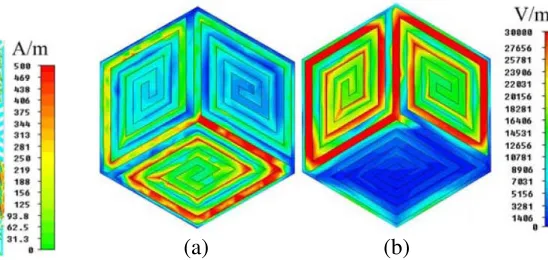
Figures 3 and 4 show the performance of the FSS when illuminated by normal incident waves. From the Fig. 3, it can be observed that the spiral structure increases the length of the current flowing, which means the equivalent inductance increased. Fig. 4 depicts that the E-field is full of the patches between the metal strips. In FSS design, conducting grids appear inductive to incident waves while arrays of conducting patches appear capacitive [9]. Physically, when illuminated by incident waves, a unit cell of a FSS can be treated as a resonance circuit, in which the resonant frequency is determined by the formula f = 1/(2π√LC) which indicates that increasing equivalent inductance and capacitance is an effective way to realize the miniaturization of FSS.
Figure 5 shows the transmission line model of the structure. The reflection coefficient Γ can be written as
Γ =− RA(jωC+ 1/jωL)
RA(jωC+ 1/jωL) + 1 (1)
(a) (b)
Figure 1. Structure of unit cell: (a) Top view; (b) Perspective view.
Figure 2. Structure of the FSS array.
(a) (b)
Figure 3. Surface current distribution diagrams at 3.14 GHz: (a) TE incident wave; (b) TM incident wave.
(a) (b)
When jωC + 1/jωL= 0, the FSS has bandpass characteristic. If Dx and Dy are both less than 0.35λ, the changes of jωC+ 1/jωLcan be ignored which means that the resonant frequency stability of the structure is great [10]. The smaller Dx and Dy are, the biggerRAis and the less Γ changes with the varying incident angle. Angle stability can also be improved by the miniaturization of the elements.
2.2. The Simulated Results
In actual implementation, it is essential that FSS provides stable characteristics under different incident angles and polarizations.
Figures 6 and 7 show transmission coefficients of the FSS proposed for various incident angles when
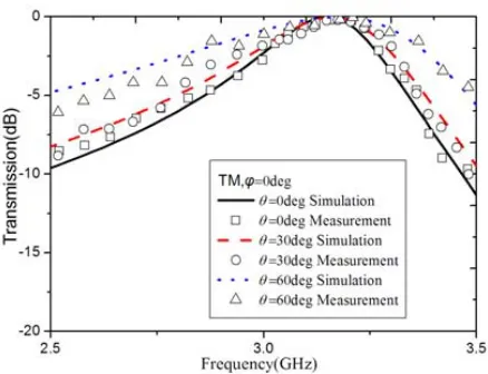
ϕ= 0. In the TE case, bandwidths of the passband become narrower as the incident angle increases. Conversely, the bandwidth of the TM case becomes wider with the increase of the incident angle and the resonant frequency shifts to a little higher frequency when the incident angle increases. For TE incident wave, there is no deviation of resonant frequency. There is only 0.63% and 1.3% deviation for TM-polarized waves of 30◦ and 60◦ incident angle. Figs. 8 and 9 show transmission coefficients of the FSS proposed for various incident angles when ϕ = 90◦. It is very obvious that the difference is so little between Figs. 6 and 8, and the same condition with the difference between Figs. 7 and 9. The simulation results indicate that the structure has great angle stability.
The dielectric substrate can help improve the miniaturization performance. The higher the relative dielectric constant is, the better the miniaturization is. So the size of the structure proposed in the letter can be further miniaturized. However the increase of the relative dielectric constant will raise the insertion loss. Fig. 10 shows the transmittances of the FSSs with different dielectric substrates.
To further prove the excellent miniaturization of the proposed structure, comparison of different structures proposed in previous papers is carried out, and the results are presented in Table 1. The thickness of the dielectric substrate used in the reference papers is the same as that in this letter or
Figure 5. Transmission line model of the Structure.
Figure 6. Transmittances of the FSS when illuminated by TE-polarized waves of different incident angles.
Figure 8. Transmittances of the FSS when illuminated by TE-polarized waves of different incident angles.
Figure 9. Transmittances of the FSS when illuminated by TM-polarized waves of different incident angles.
Figure 10. Transmittances of the FSSs of different material permittivity.
Figure 11. Photographs of the proposed miniaturized FSS.
larger than that in this letter. From the comparison, it can be observed that the proposed FSS improves the miniaturization performance.
A prototype was fabricated and measured to validate the simulation results. The photographs of the prototype are shown in Fig. 11. The sample used in measurement has 50×56 unit cells, and its dimension is 263×260 mm2. The material for substrate is F4B, and the parameters are same with simulation.
Table 1. Results of camparison to other FSSs.
εr FSS structure Unit cell size
2.33 structure in [11] 0.20λ0×0.20λ0 structure proposed 0.044λ0×0.044λ0
2.65 structure in [4] 0.077λ0×0.077λ0 structure proposed 0.042λ0×0.042λ0
3.4 structure in [12] 0.086λ0×0.086λ0 structure proposed 0.046λ0×0.046λ0
5.0 structure in [7] 0.061λ0×0.061λ0 structure proposed 0.041λ0×0.041λ0
Figure 12. Measured and simulated transmit-tances of the FSS for TE-polarized.
Figure 13. Measured and simulated transmit-tances of the FSS for TM-polarized.
3. CONCLUSIONS
A compact band-reject FSS design with stable response is proposed in this paper, and the miniaturization of the design is compared with other structures presented in previous papers. The proposed structure has excellent miniaturization with dimension of the unit cell only 0.042λ0×0.042 (λ0 represents the wavelength at the resonant frequency 3.14 GHz). Moreover, the proposed structure also shows excellent polarization stability and angle stability. Both simulation and measurement results prove great characteristics of the FSS. By virtue of these advantages, the FSS proposed is suitable for the practical application in limited space.
REFERENCES
1. Munk, B. A.,Frequency Selective Surfaces: Theory and Design, Wiley, New York, 2000. 2. Vardaxoglou, J. C.,Frequency Selective Surfaces, Wiley, New York, 1997.
3. Zhang, J.-C., Y.-Z. Yin, and J.-P. Ma, “Design of narrow band-pass frequency selective surfaces for millimeter wave applications,” Progress In Electromagnetic Research, Vol. 96, 287–289, 2009. 4. Yang, H.-Y., S.-X. Gong, P.-F. Zhang, F.-T. Zha, and J. Ling, “A novel miniaturized frequency
5. Bayatpur, F. and K. Sarabandi, “Single-layer high-order miniaturized-element frequency selective surfaces,”IEEE Trans. Microw. Theory Tech., Vol. 56, No. 4, 774–781, 2008.
6. Dorsey, W. M., C. S. McDermitt, F. Bucholtz, and M. G. Parent, “Design and performance of frequency selective surface with integrated photodiodes for photonic calibration of phased array antennas,”IEEE Antennas and Wireless Propagation Letters, Vol. 58, 157–162, 2012.
7. Yang, G., T. Zhang, W. Li, and Q. Wu, “A novel stable miniaturized frequency selective surface,” IEEE Antennas and Wireless Propagation Letters, Vol. 9, 1018–1021, 2010.
8. Liu, H. L., K. L. Ford, and R. J. Langley, “Design methodology for a miniaturized frequency selective surface using lumped reactive components,”IEEE Transactions on Antennas Propagation, Vol. 57, No. 9, 2732–2738, 2009.
9. Mohamadi, F. M. and N. Komjani, “Bandwidth enhancement of microstrip patch antenna using jerusalem cross-shaped frequency selective surfaces by invasive weed optimization approach,” Progress In Electromagnetics Research, Vol. 121, 103–120, 2012.
10. Yuan, Z.-D., J. Gao, X.-Y. Cao, and H.-H. Yang, “A novel frequency selective surface with stable performance and its application in microstrip antenna,” Acta Phys. Sin., Vol. 63, No. 1, 014102, 2014.
11. Zheng, S., Y. Yin, J. Fan, and X. Yang, “Analysis of miniature frequency selective surfaces based on fractal antenna-filter-antenna arrays,” IEEE Antennas and Wireless Propagation Letters, Vol. 11, 240–243, 2012.