2Assoc Prof, Dept of EEE, J.B Institute of Engineering and Technology (UGC Autonomous), Hyderabad,
E-mail: [email protected]
3
Professor & HOD, EEE Dept. JB Institute of Engineering and Technology (UGC Autonomous), Hyderabad. Email: [email protected]
Abstract--
This paper presents A Modified Current Loop Controller for 3 Phase Power Converter connected to a Distribution System. PI controller is used to regulate voltages and currents, while a phase-locked loop algorithm is used to synchronize the grid and DG. And along with that the operation of a distributed generation (DG) system driven by a dc-dc step-up converter and a dc-ac voltage source inverter (VSI) interfaced with the power grid. To create a stable mode when different kinds of loads are connected locally or when working under contingency, the step-up converter must regulate the dc link voltage, allowing the VSI to stabilize its terminal voltage.Keywords
: Distributed generation (DG) and power converters.1. Introduction
Recently, due to the high price of oil and the concern for the environment, renewable energy is in the limelight. This scenario has stimulated the development of alternative power sources such as photovoltaic panels, wind turbines and fuel cells [1]–[3]. Among renewable energy systems, photovoltaic (PV) systems are expected to play an important role in the future and, as such, a great deal of research effort is dedicated to enhancing their performance and efficiency at the component and system levels. As two influential factors in regards to the performance and efficiency of a PV system, the impact of characteristic mismatches amongst PV cells and the phenomenon of maximum-power drop due to partial shading have been the subject of intense research. The distributed generation (DG) concept emerged as a way to integrate different power plants, increasing the DG owner’s reliability, reducing emissions, and providing to command the voltage source inverter (VSI) additional power quality benefits [4]. The cost of the distribution power generation system using the renewable energies is on a falling trend and is expected to fall further as demand and production increase. The energy sources used in DG systems usually have different output characteristics, and for this reason, power electronic converters are employed to connect these energy sources to the grid. In a PV system, PV modules are connected in series and in parallel in order to enable power generation and processing a tan adequately large voltage level and efficiency. However, when PV cells in a module are shaded, they experience a significant power output drop
and can even act as loads to other (UN shaded) cells and modules.
This phenomenon can result in hot-spot formation in, and potential damage of, the shaded cell(s), in addition to a disproportionate maximum-power drop in the overall array.
2. CHARACTERISTICS OF THE
DISTRIBUTION GENERATION SYSTEM
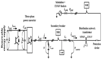
Fig. 1 shows a diagram of the system used to analyze a typical connection of a DG system to a specific feeder, although studies to determine the best site for DG insertion should be performed before the operation analysis [7]. A power plant represents a secondary source (DG systems), while in this study the standard grid is a basic configuration system found in 1547 standard (simulated system) [23] or a California Instruments LX 4500 source (experimental setup). Furthermore, the primary energy used in the proposed DG system is the same as the previously mentioned renewable energy sources.
A dc-dc converter is employed to equalize the dc link voltage and deliver energy for fast transients when required by the local load, while a dc-ac converter is used to guarantee the power quality delivered to customers (local load) and the specific feeder. To avoid disturbances between the dc-ac converter and the feeder, a phase-locked loop (PLL) algorithm [11] associated with the zero voltage crossing detectors was used [24], [25]. Appendix I shows the design procedure for key passive components.
Fig. 1 General diagram of the distributed
generation system
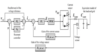
Fig. 2 Block diagram of the dc voltage/current
control
2.1 DC-DC Converter
A dc-dc step-up converter was used as an interface between the dc source and dc link of the three-phase dc-ac converter, as shown in Fig. 2. The step-up converter boosts the dc voltage and supplies the fast transients of energy required for the local load, thereby minimizing disturbances in the feeder current.
The behaviour of the step-up converter is similar to a voltage source, and the power it delivers to the grid depends on the point of maximum power (PMP) defined by the dc source. The PMP is obtained using a tracking algorithm, based on the primary energy source.
To keep the converters operating in a stable mode, proportional-integral (PI) controllers were used as a control technique to stabilize the Lboost current and dc voltage (vDC). A method based on phase-margin (mf) and cutoff frequency (FCL) was used to obtain the PIs constants (1) and (2) [2], [16], where the open loop gain (GOL), angular frequency (ωFCL), and mf define the PIs constants (kprop and kint)
Tables I and II display the main design parameters to determine the PIs constants of the boost converter [2], namely, Hi_boost and Hv_DC gains for the dc current and voltage sensors, respectively.
2.2 DC-AC Converter
Closed-loop controls of the output current and voltage were implemented to guarantee inverter voltage quality. PIs controllers were also used as the control technique, while the design method of these PIs is the same as that used in the dc-dc step-up converter.
Fig. 3 Block diagram of the ac voltage/current
control
2.3 Grid Characteristics
In the simulations, the complete distribution system found in 1547 standard [23] is composed of 13.8-kV feeders connected to a 69-kV radial line through 69/13.8-kV substation transformers, as shown in Fig. 1. To insert the DG at the distribution system, a 13.8/0.38 kV distribution network transformer is required to equalize the voltage levels. The line model employed in the simulations took into account the Bergeron’s travelling wave method used by the Electromagnetic Transients Program, which utilized wave propagation phenomena and line end reflections.
2.4 Synchronization Algorithm
To connect the DG to the grid, it is essential to synchronize both systems, which is done by means of a PLL algorithm that computes the average of the internal product between v source and the synchronous voltage (v_ ⊥) [24], [33]. If this equals zero in steady-state regime, v_⊥ and vsource are perpendicular and synchronized [25]. The integration of the angular frequency (ω) then defines the θ angle (θ = wt) used as the argument to produce v_⊥. Due to the high sampling and switching frequency Ts ≈ 0, the delay block can be dismissed in the PLL closed loop transfer function.
Fig. 4 PLL algorithm
To compare the characteristic equation of the prototype transfer function with the PLL closed-loop transfer function (7), PI constants (8) and (9) can be adjusted by choosing the most suitable values for the natural un damped frequency (ωn) and damping ratio (ξ). To avoid stability problems, ωn should ideally be greater than one or two periods of the fundamental frequency, and the maximum overshoot lower than 30%.
A general description of the PLL algorithm is found in Fig. 4, where ωr, Δω, and Hv are the rated angular frequency (= 2π60), adjusted angular frequency, and voltage sensor gain (1/360) (voltage measured at the grid), respectively.
3. POWER CONTROL THROUGH THE
FEEDER
Energy produced by the renewable energy sources can be transferred to the grid by controlling the amplitude of the voltage produced by the DG, and the angle between the grid voltage and the DG voltage (β angle) through a coupling inductor (LS). This serves as an additional inductance placed to connect the DG to the grid, or the leakage inductance of the DT. If LS is a DT parameter, v source must be measured on the high voltage side of the distribution network transformer. To achieve a controlled power flow from the DG to the grid, the DG voltage angle (V A) must be ahead of the grid voltage angle (V A source). When this occurs, the DG delivers active power to the grid, as shown in Fig. 5 [28]. The same analysis can be applied to the ac voltage amplitude produced by the DG: if the amplitude of V A is greater than V A source the DG delivers reactive power to the grid; however, if the amplitude of V A is less than V A sources
the DG absorbs reactive power from the grid.
Fig. 5 Phasor diagrams. (a) Delivering active
and reactive power. (b) Delivering active and
absorbing reactive power
β
to the grid (P source), the connection reactance (XLS), the rms phase voltage (V A source) synthesized by the grid, and the rms voltage produced (VA) by the DG according to (10). After defining the β angle, the DG voltage amplitude of V A must be adjusted according to (11), where V Asource and XLS are the same parameters described in (10). If Q source = 0 the unity power factor (PF) to the feeder is obtained [34]. Additionally, LS is designed for a small voltage variation on the ac local voltage produced by the dc-ac inverter. In Fig. 6, the voltage reference (vref ) of the dc-ac power converter is determined by displacing θ by π/2 and adding the β angle to the result. The φ angle is then used as the argument of a sinusoidal function and multiplied by VA to obtain the voltage reference that must be synthesized at the VSI terminals.
4.
PROPOSED CONTROL
STRATEGY
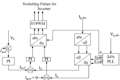
Fig. 7 shows the detailed block diagram of the constant current controller for generating the controlled switching pulses for the Renewable Energy inverter such that the output voltage should be able to interface the grid. The 3-phase_ Phase Locked Loop calculates the phase angle of the utility grid and also gives the information about the frequency variation. According to the phase angle of the utility grid voltage, the constant current controller is modeled such that the controller is able to generate the switching pulses for Renewable Energy inverter for tracking the phase of the grid voltage. The 3-phase grid current Ig_abc is converted into αβ variable using the Clarke transformation. The αβ variables are transformed into the dq variables. The current Id and Iq are compared with the Idref and Iqref for processing in the PI controller to minimize the errors. These signals are transformed into 3-pahse signal using the inverse park’s transform and then compared with the triangular waveform for generating the PWM switching pulse for the Renewable Energy inverter. The Vdc and Vdcref is the DC link voltage of the Renewable Energy and expected DC voltage of the Renewable Energy.
Fig. 7 Block Diagram of Proposed Control Strategy
4. SIMULATION RESULTS
Fig. 8 Simulation of existed system
Fig. 9 Simulation of Proposed System
Fig. 10 grid voltages, grid current and load voltages in existed system
Fig. 11 THD spectrum of grid currents (existed)
Fig. 12 THD spectrum of grid currents (proposed)
5. CONCLUSIONS
This paper presents an alternative solution to connecting a DG system to the grid, whereby the amplitude and displacement of the voltage synthesized by the DG is regulated with respect to the grid voltage and the control variable before and after the contingency is always the same. Additionally, a dc-dc step-up converter and a dc-ac VSI are used in a DG system as an interface with the power grid. The simulation and experimental results demonstrate that the connection of DG sources can have adverse effects, depending on the connection procedures.
REFERENCES
[1] F. P. Marafão, S. M. Deckmann, J. A. Pomilio, and R. Q. Machado, “Metodologia de projeto e análise de algoritmos de sincronismo PLL,” SOBRAEP Revista da Associação Brasileira de Eletrônica de Potência, vol. 10, no. 1, pp. 7–14, 2005.
[2] V. Kaura and V. Blasko, “Operation of a phase locked loop system under distorted utility conditions,” IEEE Trans. Ind. Appl., vol. 33, no. 1, pp. 58– 63, Jan./Feb. 1997.
[3] J. M. E. Huerta, J. Castello-Moreno, J. R. Fischer, and R. Garcia-Gil, “A synchronous reference frame robust predictive current control for three phase grid-connected inverters,” IEEE Trans. Ind. Electron., vol. 57, no. 3, pp. 954–962, Mar. 2010.
[4] P. Rodriguez, A. V. Timbus, R. Teodorescu, M. Liserre, and F. Blaabjerg, “Flexible active power control of distributed power generation systems during grid faults,” IEEE Trans. Ind. Electron., vol. 54, no. 5, pp. 2583–2592, Oct. 2007.
[5] F. Gao, S. Member, and M. R. Iravani, “A control strategy for a distributed generation unit in grid-connected and autonomous modes of operation,” IEEE Trans. Power Del., vol. 23, no. 2, pp. 850–859, Apr. 2008.
[6] H. Kim, T. Yu, and S. Choi, “Indirect current control algorithm for utility interactive inverters in distributed generation systems,” IEEE Trans.Power Electron., vol. 23, no. 3, pp. 1342–1347, May 2008.
[7] Agência Nacional de Energia Elétrica—ANEEL, Procedimento de Distribuição de Energia Elétrica no Sistema Elétrico Nacional— PRODIST—Módulo 82010.
IEEE Trans. Ind. Appl., vol. 33, no. 1, pp. 58– 63, Jan./Feb. 1997.
[11] T. Esram and P. L. Chapman, “Comparison of photovoltaic array maximum power point tracking techniques,” IEEE Trans. Energy Convers., vol. 22, no. 2, pp. 439–449, Jun. 2007.
[12] R. Q. Machado, A. F. Q. Gonçalves, S. Buso, and J. A. Pomilio, “An electronic solution for the direct connection of a three-phase induction generator to a single-phase feeder,” SBA: Controle & Automação Sociedade Brasileira de Automatica, vol. 20, no. 3, pp. 417–426, Jul./Sep. 2009.
[13] IEEE Recommended Practice for Industrial and Commercial Power Systems Analysis, IEEE Std. 399, 1998.
[14] IEEE Application Guide for AC High-Voltage Circuit Breakers Rated on a Symmetrical Current Basis, IEEE Std. C37.010, 2005.
[15] J. Rocabert, G. M. S. Azevedo, A. Luna, J.M. Guerrero, J. I. Candela, and P. Rodríguez, “Intelligent connection agent for three-phase grid-connected microgrids,” IEEE Trans. Power Electron., vol. 26, no. 10, pp. 2993–3005, Oct. 2011.
[16] E. Acha, C. R. Fuerte-Esquivel, H. Ambriz-Pérez, and C. Angeles- Camacho, Facts Modelling and Simulation in Power Electronics. Hoboken, NJ: Wiley, 2004.
[17] E. J. Estébanez, V. M. Moreno, A. Pigazo,M. Liserre, and A. Dell’Aquila, “Performance evaluation of active islanding-detection algorithms in distributed-generation photovoltaic systems: Two inverters case,” IEEE Trans. Ind. Electron., vol. 58, no. 4, pp. 1185– 1193, Apr. 2011.
[18] K. Jae-Hyung, K. Jun-Gu, J. Young-Hyok, J. Yong Chae, and W. Chung-Yuen, “An islanding detection method for a grid-connected system based on the goertzel algorithm,” IEEE Trans. Power Electron.,
vol. 26, no. 4, pp. 1049–1055, Apr. 2011.
[19] A. M. McLandrich, “Sensorless control of a bidirectional boost converter for a fuel cell energy management system,” M.S. thesis, Faculty Virginia Polytechnic Inst. State Univ., Blacksburg, VA, 2003. [20] R. Gopinath, K. Sangsun, H. Jae-Hong, P. N. Enjeti, M. B. Yeary, and J. W. Howze, “Development of a low cost fuel cell inverter system with DSP control,” IEEE Trans. Power Electron., vol. 19, no. 5, pp. 1256–1262, Sep. 2004.
Challa Narasimha Reddy, at present is pursuing M. Tech in the department of EEE, JBIET (Autonomous) College, Hyderabad, TELANGANA,INDIA. He received B. Tech degree in Electrical and Electronics Engineering from J.N.T.University, Hyderabad, T.S, India
Email:
[email protected]Automation on the topic of “ Minimax Approach to linear filtering Problems with uncertainties”. He has worked with Dr. APJ Abdul Kalam in Project SLV of Vikram sarabhai space centre for four years in mission analysis group.