IJISET - International Journal of Innovative Science, Engineering & Technology, Vol. 2 Issue 11, November 2015. www.ijiset.com
ISSN 2348 – 7968
A Study on the Effect of Shear Connectors in Composite
Beams
Jobil Varghese, Bincy George
1
INTRODUCTION
Abstract—
Concrete is a versatile construction materi-al which has severmateri-al advantages due to its compressive strength and mouldable shape. But it is weak in tensionand has poor ductility. Ductility is an important characteristic of a structure to resist earthquake, impact
and blast loading. Steel has excellent ductile property. Hence a judicious combination of structural steel and concrete utilizing the strength possessed by them and suppressing their weakness resulted in the composite construction. Steel-concrete composite structures, par-ticularly, are structures consisting of two materials, a steel section located mainly in the tension region and a concrete section located in the compression cross sec-tional area. Composite action between the steel and the concrete is achieved by means of mechanical connect-ors. They are typically connected by welding to the top flange of a steel beam and cast within the concrete slab. Without these connectors, the concrete and the slab act independently. The main functions of these connectors are to restrict longitudinal slipping and uplifting at the elements interface and to take shear forces. The project work deals with the analysis of composite beams. Analy-sis was done using ANSYS finite element software. The model provided by ANSYS is used to simulate the behav-iour of shear connectors in composite beam. The com-parison is done between flexible and rigid shear con-nectors.
Index Terms— Composite Structures, Shear
Connectors, Stud Connector, Channel
Con-nectors, Finite Element Method, Von-mises
Stress, Crack Pattern.
Modern civilization relies upon the continuing performance of civil engineering infrastructure ranging from industrial building to power station and bridges. For the satisfactory performance of the existing structural system, the need for strengthening is inevitable. Commonly encountered engineering challenges such as increase in service loads, changes in
use of the structure, design and/or construction errors, degradation problems, changes in design code regulation and seismic retrofits are some of the causes that lead to
the need for new techniques to upgrade the performance of the structures. Though concrete a versatile construction material has several advantages due to its compressive strength and mouldable shape, it has its own tensional limitation and poor ductility. Ductility is an important characteristic of a structure to resist earthquake, impact and blast loading. Steel has excellent ductile property. Hence a judicious combination of structural steel and concrete utilizing the strength possessed by them and suppressing their weakness resulted in the composite construction. The present day demands in construction on parameters such as strength, safety, serviceability, satisfactory and reliable performance expected of a structure apart from economical solutions has also made it imperative to use steel concrete composite construction techniques. A structural member as a unit is referred as composite structure. Joining two dissimilar materials to form a composite member does not only combine the collective strengths of the two materials, forming a union between relevant materials actually enhances their physical characteristics and makes the composite stronger than the sum of their strengths. An example is the steel-concrete composite beam in which a steel wide-flange shape (I or W shape) is attached to a concrete floor slab. Steel-concrete composite structures, particularly, are structures consisting of two materials, a steel section located mainly in the tension region and a concrete section, located in the compression cross sectional area , both connected by metal devices known as shear connectors. The main functions of these connectors are to allow for the joint behaviour, to restrict longitudinal slipping and uplifting at the elements interface and to take shear forces. In these composite sections, the greatest shear stress occurs at the neutral axis which is always near the top flange of the joist. Objective of this study is to find the behavior of shear connectors in com-posite beams under incremental loading.
• Jobil Varghese is currently working as Assistant Professor in Mar Baselios Institute of Technology and Sci-ence, Nellimattom, INDIA, PH-9446081071.
E-mail:[email protected]
• Bincy George is currently pursuing masters degree program in Computer Aided Structural Engineering in MG University, INDIA, PH-8547588549.E-mail:[email protected]
2 SHEAR
CONNECTORS
Composite construction consists of providing monolithic action between prefabricated units like steel beams or pre-cast reinforced concrete or pre-stressed concrete beams and cast-in-situ concrete, so that the two will act as one unit. Although there is bound to be a certain amount of natural bond between concrete and steel at least at the initial stages, this bond cannot be relied upon as the same is likely to be deteriorate due to use and over load. Mechanical shear connectors are therefore provided to help the steel and concrete element to act in a composite manner ignoring the contribution made by the inherent natural bond towards this effect.
Primarily shear connectors are intended to resist the horizontal movement between the concrete slab and the steel beam and to transmit the horizontal shear between the two. Shear Connectors are also called upon to prevent vertical separation of the slab from the steel girder at the contact surface to transmit the longitudinal shear along the contact surface without slip. There are different types of shear connectors namely, rigid, flexible and bond type connectors.
2.1 Rigid Type Connectors
As the name implies, these connectors are very stiff and they sustain only a small deformation while resisting the shear force. They derive their resistance from bearing pressure on the concrete, and fail due to crushing of concrete. Short bars, angles, T-sections are common examples of this type of connectors. Also anchorage devices like hoped bars are attached with these connectors to prevent vertical separation.
2.2 Flexible Type Connectors
Headed studs come under this category. These connectors are welded to the flange of the steel beam. They derive their stress resistance through bending and undergo large deformation before failure. The stud connectors are the types used extensively. The shank and the weld collar adjacent to steel beam resist the shear loads whereas the head resists the uplift.
3 OBJECTIVE
The objective is to compare the flexible and rigid type shear connectors in composite beams. These verifications were made by means of the study of vertical displacement, von-mises stress and crack pattern of the composite beams.
4 FINITE
ELEMENT
MODEL
4.1 Numerical Modelling
The composite beam is a simply supported beam and the interaction between the concrete and steel I-section is provided by stud connectors. The length of the simple composite steel-concrete beam was 5490 mm.The concrete slab had a depth of 152mm and a width of 1220 mm whereas the steel I-section beam had a depth of 305 mm, a flange depth of 18 mm, flange width of 152 mm and web thickness of 10 mm. The beam is subjected to a point load in the mid span. The model implementation started with the definition of the geometry of the composite beam. Secondly, finite elements were chosen to represent the composite materials. Thirdly, the properties and constitutive relations of the materials involved were introduced. Finally, the meshing was done considering the beam support conditions and the applied load. Then, to analyze the connector’s influence on the structural behavior of the composite beam, the stud connector and channel connectors are used alternatively. The material properties are given in table 1.
Fig. 1. Rigid type shear connectors
Fig. 2. Flexible type shear connectors
TABLE
1
MATERIAL PROPERTIES4.2 Software and Element Types
Advances in computational features and software have brought the finite element method within reach of both academic research and engineers in practice by means of general purpose nonlinear finite element analysis packages, with one of the most used nowadays being ANSYS. In this paper, the structural system modelling is based on the use of this commercial software.
The finite element types considered in the model are as follows: shell (SHELL43) and solid (SOLID65) el-ements are used for the steel section and the concrete slab respectively. The three dimensional element SOLID65 were adopted to discretize the concrete, which are also able to simulate cracking behavior of concrete in tension and crushing in compression, to evaluate the material non-linearity and also to enable the inclusion of reinforcement. The nonlinear springs (COMBIN39) to represent the shear connectors. Link180 is used for the reinforcing bars and CONTA174 and TARGE170 is provided for the contact between concrete and steel section.
4.3 Stud and Channel Connectors
To analyze the connector’s influence on the structural behavior of the composite beam, the stud connectors and channel connectors were used. The stud connectors with 22mm diameter were used first and then channel connectors are used. The height of the stud connector is kept as 102mm. In order to compare stud connector and channel connector, their area should be kept equal. So the number of channel connectors corresponding to 72nos of stud connector is 40 nos. The composite beam is subjected to a point load on mid span.
5 RESULTS
AND
DISCUSSIONS
The structure was analyzed and the deflection, von-mises stress and crack pattern were studied for stud and channel connectors.
5.1 Influence of Stud Connectors
The study was conducted by using stud connector with 22mm connectors. The number of connectors was kept as 76mm and height as 102mm.
5.1 (a) Deflection Diagram
5.1 (b) Von Mises Stress
The Von Mises yield criterion predicts that yielding will occur whenever the distortion energy in a unit volume equals the distortion energy in the same volume when uniaxially stressed to the yield strength.
CONCRETE
Modulus of Elasticity
2.1 x 10
7N/m
2Poisson’s Ratio
0.15
Density
25 kN/m
3STEEL
Modulus of Elasticity
2.1 x 10
11N/m
2Yield stress
250 MPa
Poisson’s Ratio
0.3
Density
7850 kg/m
3
Fig. 3. Meshed model
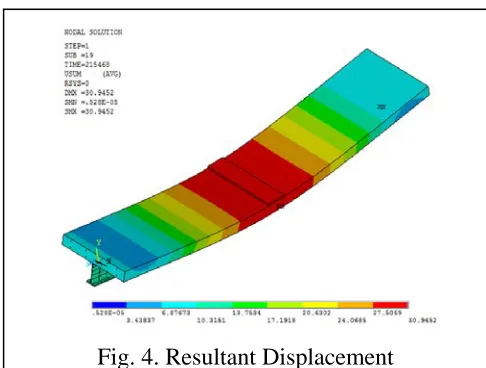
Fig. 4. Resultant Displacement
5.1 (c) Crack Pattern
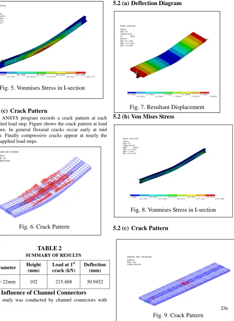
The ANSYS program records a crack pattern at each applied load step. Figure shows the crack pattern at load failure. In general flexural cracks occur early at mid span. Finally compressive cracks appear at nearly the last applied load steps.
TABLE
2
SUMMARY OF RESULTSParameter Height
(mm)
Load at 1st crack (kN)
Deflection (mm)
Φ = 22mm 102 215.468 30.9452
5.2 Influence of Channel Connectors
The study was conducted by channel connectors with
height 80mm, length 30mm, web thickness 4.5mm and with flange thickness of 6.5mm.
5.2 (a) Deflection Diagram
5.2 (b) Von Mises Stress
5.2 (c) Crack Pattern
Fig. 5. Vonmises Stress in I-section
Fig. 6. Crack Pattern
Fig. 7. Resultant Displacement
Fig. 8. Vonmises Stress in I-section
Fig. 9. Crack Pattern
TABLE
3
SUMMARY OF RESULTSNumber of Connectors
Load at 1st crack (kN)
Maximum stress (MPa)
Deflection (mm)
40 198.235 176.499 17.3803
6 COMPARISION
BETWEEN
RIGID
AND
FLEXIBLE
TYPE
SHEAR
CONNECTORS
TABLE
4
COMPARISON OF RESULTSStud connector Channel connector
Maximum load = 215.468 kN
Maximum load = 198.235 kN Maximum deflection
= 30.95 mm
Maximum deflection = 17.3803 mm
The stud connector is a flexible connector and channel connector is a rigid type shear connector. As the stud connector is flexible shear connector, it can undergo large deformation without failure than rigid connectors. The stud connector can also take more loads than channel connectors.
7 CONCLUSION
In this study, three-dimensional finite element models have been developed to investigate the effect of shear connectors in composite beams. The study was conducted by using stud and channel type shear connectors. A comparison is done between rigid and flexible type connectors. As the stud connector is flexible shear connector, it can undergo large deformation without failure than rigid connectors. The
stud connector can also take more loads than channel connectors. The maximum stresses were obtained within the permissible limit.
ACKNOWLEDGMENT
First of all, I would like to thank Almighty God and my family. I express my sincere thanks and regards to Mr. Jobil Varghese, Assistant Professor, Dept. of Civil Engineering, and MBITS Nellimattom for his constant encouragement throughout my work. I would like to extend my heartfelt gratitude to all the staff members, Dept. of Civil Engineering, MBITS Nellimattom for their direct and indirect support during this work. I
would also like to thanks my friends for their valuable co-operation and suggestions.
R
EFERENCES[1] I.M. Viest, “Investigation of stud shear connectors for composite concrete and steel T beams”, American Concrete Institute, Journal Proceedings, Volume-52, Issue-4, 1956, pp 875-892.
[2] P.S.Patil, M.G.Shaikh, “A Study of Effect of Shear Connector in Composite Beam in Combined Bending and Shear by Ansys”, International Journal of Innovative Technology and Exploring Engineering (IJITEE) ISSN: 2278-3075, Volume-3, Issue-3, August 2013.
[3] Qing Quan Liang, “Strength Analysis of Steel–Concrete Composite Beamsin Combined Bending and Shear”, Bri-an Uy, Mark A. Bradford, Hamid R. Ronagh, Journal of Structural Engineering, ASCE / October 2005, 1593-1600.
[4] Dennis Lam, Ehab El-Lobody, “Behaviour of Headed Stud Shear Connectors in Composite Beam”, Journal of Structural Engineering, ASCE / January 2005, 131:96-107.
[5] F.D. Queiroz, Vellasco, D.A. “Finite element modelling of composite beams with full and partial
shear connection”, Nethercot, Journal of Constructional Steel Research, 63(2007) 505–521.
[6] Amar Prakash, N. Anandavalli, C. K. Madheswaran, J. Rajasankar, N. Lakshmanan, “Three Dimensional FE Model of Stud Connected Steel-Concrete Composite Girders Subjected to Monotonic Loading”, International Journal of Mechanics and
Application,. 2011, 1(1):1-11.
[7] Amar Prakash, N. Anandavalli, C. K. Madheswaran, N. Lakshmanan, “Modified Push-out Tests for Determining Shear Strength and Stiffness of HSS Stud Connector-Experimental Study”, International Journal of Composite Materials, 2012, 2(3):22-31. [8] Shreeja Kacker, Dr. Arun Kumar, “Comparative
Study of the Shear Resistance of Different Types of Shear Connectors in Steel Beam-Concrete Slab Composite Construction”, International Journal of Engineering Research & Technology (IJERT) ISSN: 2278-0181, Vol. 3 Issue 12, December-2014.
[9] Daniel Lowe, Raj Das, Charles Clifton, “Characterization of the splitting behavior of
steel-concrete composite beams with shear stud connection”, Procedia Materials Science 3 (2014) 2174 – 2179.
[10]Shervin Maleki, Saman Bagheri, “Behavior of channel shear connectors, Part II: Analytical study”, Journal of Constructional Steel Research 64 (2008) 1341–1348.