109
Response of Blast Loading on R.C structures
Jay Krishna
1, Eldhose Cheriyan
21Mtech student , Sree Narayana Gurukulam College of Engineering
2
Assitant Professor, Sree Narayana Gurukulam College of Engineering Email: [email protected]
Abstract- The increase in the number of terrorist attacks in the last few years had shown that the effect of blast loads on buildings is a severe matter that should be taken into consideration in the design process. Blast loads are actually dynamic loads that need to be judiciously calculated just like earthquake and wind loads. In the present study, it is focused to know, the response of concrete frames subjected to self-weight and lateral blast loads for three bay-ten storey structure for charge weight of 2500kg TNT of 10m range. Five different types of frames like bare frame, frame with infill walls of 0.115m and 0.23m thick and frame with infill walls of 0.115m and 0.23m thick with central openings. ETABS was used to model concrete frame.
Keywords : Blast load, terrorist attacks, response
1. INTRODUCTION
Damage to the assets, loss of life and social panic are factors that have to be minimized if the threat of terrorist action cannot be stopped. Designing the structures to be fully blast resistant is not a realistic and economical option, however current engineering and architectural knowledge can enhance the new and existing buildings to mitigate the effects of an explosion.[3]
1.1 Blast
An explosion is a rapid release of potential energy characterized by eruption energy to the atmosphere. A part of energy is converted to thermal energy radiation and a part is coupled as air blast and shock waves which expand rapidly.[4]
1.2 Blast loading categories
Blast load on structures can be divided into two main groups based on the confinement of the explosive charge:
i. Unconfined explosion
a) Free air burst explosion b) Air burst explosion c) Surface burst explosion ii. Confined explosion
a) Fully vented explosion b) Partially confined explosion c) Fully confined explosion
1.2.1 Free air burst explosion
An explosion, which occurs in free air, produces an initial output whose shock waves, propagates away from the center of the detonation, striking the protective structure without intermediate amplification of its wave.
1.2.2 Air burst explosion
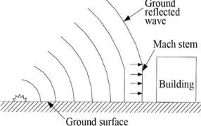
An explosion which is located at a distance from and above the protective structure so that the ground reflection of the initial wave occur prior to the arrival of the blast wave at the protective structure.
Fig 1: Air burst explosion
1.2.3 Surface burst explosion
A surface burst explosion will occur when the detonation is amplified at the point of detonation due to the ground reflections.
110 atmosphere forming a shock wave which propagates away from the structure.
Fig 3: Fully vented explosion
1.2.4 Partially vented explosion
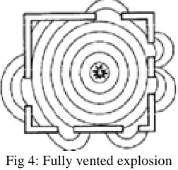
A partially confined explosion will be produced with in a barrier or cubicle type structure with limited size openings and/or frangible structures. The initial wave which is amplified by the frangible and nonfrangible portion of the structure and the products of detonation are vented to the atmosphere after a finite period of time. The confinement of the detonation products, which consists of the accumulation of high temperatures and gaseous products, is associated with a buildup of quasi-static pressure. This pressure has a long duration in comparison to that of the shock pressure.
Fig 4: Fully vented explosion
1.2.5 Fully confined explosion
Fully confinement of the explosion is associated with either total or near total containment of the explosion by a barrier structure. Internal blast loads will consist of unvented shock loads and very long duration gas pressure which are function of the degree of containment. The magnitude of the leakage pressures will usually be small and will only affect those facilities immediately outside the containment structure[2].
Fig 5: Fully confined explosion 2. OBJECTIVE OF THE STUDY
The main objective of the paper is to study the response of five different concrete frames of three bay-ten storey i.e bare frame, frames with infill walls of 0.115m and 0.23m thick & frames with central opening in infill walls. Also comparing displacement of each frame with other frames.
3. SCOPE OF THE STUDY
1. The study is restricted to three bay - ten storey with charge weight of 2500kg TNT at range of 10m. 2. Computation of the blast pressure on the frame for
surface blast only as this type of blast occur normally to structure.
3. Generally the charge wave shape is spherical but due to surface blast hemispherical wave considered.
4. Hemispherical charge wave shape is considered for the calculation of blast parameters.
5. Only positive phase of the blast load curve is taken for the study as negative phase had no major influence on the structures.
6. The bay dimension is maintained as 4m and the height of each storey is 3m.
7. The selected dimension is normally seen in structure but dimension of bay and storey height does not have any influence on structures.
4. METHODOLOGY
1. Calculation of blast pressures and forces at different levels for charge weight of 2500kg at 10m range. Modeling of five different three bay-ten storey structure in ETABS for charge weight of 2500kg TNT. The following frames were considered: a) Bare frame
b) Frame with 0.115m thick infill walls c) Frame with 0.23m thick infill walls
d) Frame with central opening of 2 x 1m in 0.115m thick in-fill walls
2. Frame with central opening of 2 x 1m in 0.23m thick in-fill walls
111
5. ESTIMATION OF BLAST LOAD
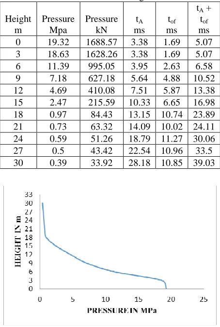
The main factors to be considered for the estimation of blast loading on the structures are the shape and magnitude of explosion, location of explosion, geometrical configuration of the structure and the orientation of the structure with respect to the explosion[2]. Parameters such as reflected pressure Prα, reflected impulse irα, time of arrival ta and Positive phase time duration tof are estimated. Distribution graphs are prepared throughout the height of the structure for the charge weights of 500, 1500 and 2500kg TNT. Pressure-time curves are prepared as shown in fig 6. For finding the blast loads , firstly find free- blast wave parameters such as peak positive incident pressure Pso , time of arrival ta , unit positive impulse is and positive phase pressure duration tof with the help of TM5-1300. Finally find peak reflected pressure with the help of reflected pressure coefficient Crα and convert this pressure into load. Table 1 shows tabulated values for 2500 kg TNT.[1]
Fig 5. Idealized free-field pressure-time variation TM 5-1300
Table 1: Pressures, time of arrivals and time of fictitious positive phase pressure duration along height
of structure for 2500kg TNT
Height
Fig 6. Idealized free-field pressure-time variation TM 5-1300
6. MODEL AND ANALYSIS
6.1 Blast Response on Five Frames for 2500 Kg TNT
112 Table 1. Displacement at different stories
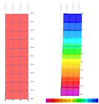
Fig 8. Model and displacement in mm of frame with 0.23m thick infill wall for 2500 kg TNT
Table 2. Displacement at different stories
113 Table 3. Displacement at different stories
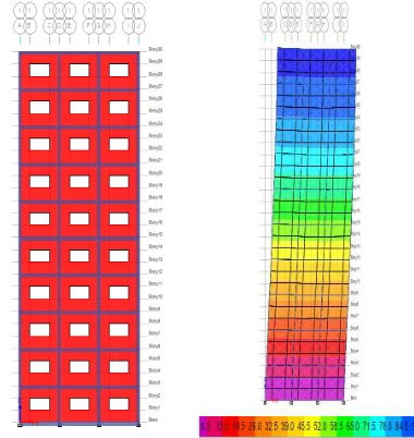
Fig 10. Model and displacement in mm of frame with 0.23 m thick infill wall with opening for 2500 kg TNT
Table 4. Displacement at different stories
Fig 11. Model and displacement in mm of frame with 0.115 m thick infill wall with opening for 2500 kg
114 Table 3. Displacement at different stories
7. RESULTS
7.1 Comparison of Bare frame and frame with 0.23m
thick wall
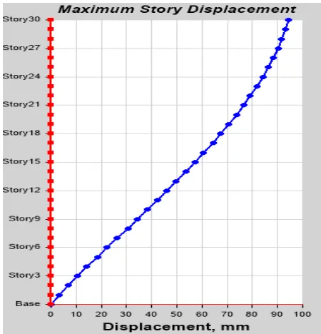
From the above comparison, there is reduction in displacement. Bare frame subjected to blast load causes large displacement than frame with 0.23 m infill walls at 30m level. Therefore frame with 0.23 m infill wall reduces displacement by 80-90%. Thus, frame with 0.23m wall is stiffer than bare frame.
7.2 Comparison of Bare frame and frame with
0.115m thick wall frame with 0.115m wall is stiffer than bare frame.
7.3 Comparison of frame with 0.23 m and 0.115 m
infill wall
From above comparison, frame with 0.115 m infill wall deflect more than frame with 0.23 m infill wall. Therefore frame with 0.23 m infill wall reduces displacement by 35-40%. Thus 0.23 m wall is stiffer than 0.115m infill wall.
7.4Comparsion of frame with 0.23m thick wall with
and without opening frame with 0.115m wall is stiffer than bare frame
7.5 Comparsion of frame with 0.115m thick wall with
and without opening
From above comparison, wall with opening provide very small increase in displacement than wall without opening. But wall without opening provide more stiffness than wall with opening because opening provide passage to blast waves through it.
CONCLUSION
While considering three bay ten storey frame subjected to 500, 1500 and 2500kg TNT at 10m range for five different frames (bare frame, frames with fill wall of 0.115m & 0.23m thick and frames with in-fill wall of 0.115m & 0.23m thick having central opening), the following are the conclusions attained: • It is observed that, 80-89% reduction of
displacement in case of bare frame with infill walls (0.23m thick) when compared to bare frames at 30m level. It is noticed that the maximum deflection occurs in the case of bare frame only. • From comparing it is seen that, 69-82% reduction in case of bare frame with infill wall (0.23 m thick) when compared to bare frames with infill wall (0.115m thick) at 30 m level. It is noticed that the maximum deflection occurs in the case of bare frame with 0.115m infill wall.
• From comparing it is seen that, slight increase of frame with infill walls (0.23 m thick) with opening when compared to frames with infill walls (0.23 m thick) without opening at 30 m level.
115 with respect to storey height is very less for the
frames with infill walls.
REFERENCES
[1] TM 5-1300(UFC 3-340-02) U.S. Army Corps of Engineers (1990), “Structures to Resist the Effects of Accidental Explosions”, U.S. Army Corps of Engineers, Washington, D.C., (also Navy NAVFAC P200-397 or Air Force AFR 88-22) [2] Harinadha Babu Raparla & Ramancharla Pradeep
Kumar(2011):Linear analysis of reinforced concrete buildings subjected to blast loads , ICI Journal
[3] T. Ngo, P. Mendis, A. Gupta & J. Ramsay(2007) Blast loading and blast effects on structures, EJSE special issue.
[4] Hrvoje Draganić, Vladimir Sigmund(2012):Blast loading on structures, Technicki Vjesnik 643-652