Analysis and Design of a Building By Using STAAD
Ashish P. Misalkar1, Bhushan S. Pakhare2, Kiran D. Gawai3, Akash A. Natthani4, Shital Jadhao5 Department of Civil engineering PLIT-MS Buldana
Email:[email protected],[email protected], [email protected], [email protected], [email protected], [email protected]
Abstract
–
An Computer aided design of a Building involves analysis of building frames by using STAAD and manual design of the frame elements. Conventional method of analysis involves lot of complications and tedious calculations such analysis is a time consuming task. Analysis can be made quickly by using software’s. STAAD and STAAD PRO is the leading design software in the market. Many design companies use this software for their project design purposes. Hence this project mainly deals with the analysis of the building by using STAAD . These analysis results will also be compared by manual calculations of a sample beam and column of the same structure and these elements are design manually as per IS 456-2000.Index Terms - STAAD , Design of RCC elements, Analysis, multi-storey building, slab, beam, column, footing and stair case etc.
1. INTRODUCTION
Structural design is an art and science of designing, with economy and elegance, a safe, serviceable, and a durable structure. The entire process of structural planning and design requires not only imagination and conceptual thinking (which form art of designing) but also sound knowledge of science of structural engineering besides knowledge of practical aspects, such as relevant design codes and bye-laws, backed up by ample experience, institution and judgment.
The process of design commences with planning of a structure, primarily to meet the functional requirements of the user or the client. The requirements proposed by the client may not be well defined. They may be vague and may also be impracticable because is not aware of the various implications involved in the process of planning and design and about the limitations and the intricacies of structural science. The functional requirements and the aspect of aesthetics are look into normally by an architect while the aspect of safety, serviceability, durability and economy of the structure for its intended use over life span of the structure are attended by the structural designers (many times, a structural engineer is require to act in capacities of both the architect and the structural designer
1.1. Stages in Structural Designs: The process of structural design involves the following stages. The process of structural design involves the following stages: Structural planning, Computation of loads, Method of analysis, Member design and Detailing, drawing and preparation of schedules.
1.2 About STAAD : It is widely used software for structural analysis and design from research engineers international it consists of following. It is
a graphical user interface, it is used to generate the model, which can then be analyzed using STAAD engine. After analysis and design is completed, and the view results graphically. The STAAD analysis and design engine: It is a general purpose calculation engine for structural analysis and integrated steel, concrete, timber and aluminum design. The documentation for STAAD consists of a set of manual as described.
1.3 Getting started:
This manual contains information on the contents of the STAAD package computer system requirements installation process, copy protection issues and description on how to run the programs in the package. Tutorials that provide detailed and step-
by-step explanation on using the program are also provided.
1.4 Graphical environment: The manual contains a detailed description of STAAD . The topics covered include mode generation, structural analysis and design, result verification and report generation.
1.5 Technical Reference: This manually deals with the theory behind engg calculations made by STAAD engine. It also includes an explanation of commands available is a STAAD command file. 1.6 Release report: This manually deals with the latest enhancement of program which is being supplied to the users as ready reference. It includes all related technical understanding and graphical changes from the last version
2. Modeling:
generating elements from complex shapes with holes.
2.1 Property and loading
thickness between nodes.
seismic load.
loading patterns.
tor which automatically updates the pressure distribution if floor changes also allows for elimination of floor members and creation of floor groups.
live load or roof load (live) as per UBC/IBC. ad on open lattice structure.
2.2 Analysis capabilities:
Static, P-Delta, Non-linear Analysis. -Delta analysis.
-linear with automatic load stiffness connection.
linear).
freedom.
octagonal, etc (excellent for poles).
only/tension only) for generation of soil springs. er/slave capabilities.
torsional stiffness.
2.3 Concrete design:
One way slab design to design irregular shaped slabs full reinforcement contour and reinforcement layout plans are created.
deep beam design) and automatically mesh all existing wall and provide horizontal, vertical and edge reinforcement, based on axial moments.
inertia for concrete design. 3. OBJECTIVES
Computer aided design of commercial cum residential building by using STAAD PR which includes.
Creating model in STAAD
ure gn the structure.
4. DESIGN PROCEDURE
A Three floor commercial cum residential building is considered whose architectural plan and
structural framing plans were prepared as shown in followings figures. The entire analysis of building has been done in one stage keeping the IS code provision in view wherever necessary. The whole building has been split into its structural components viz., slab, beams, columns and footings. These components are designed for M20 grade concrete and Fe415 grade steel.
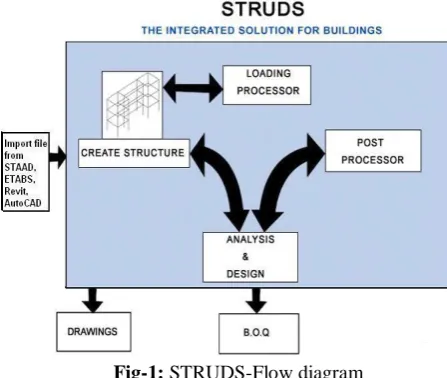
Fig-1: STRUDS-Flow diagram
Table -1: Model specification for analysis and design
Type of structure RCC Framed structure No. of floors Ground Floor + 3 floors
Location Buldana
Type of Soil Soft Murum
Types of Footing Raft Footing
Allowable bearing
pressure 452.48kN/m2 Story height 3 m
Plinth level 1.0 m
Outer periphery
walls 230 mm thick
Inner periphery
walls 115mm thick
Partition walls 115mm thick
Slab thickness 130 mm
Concrete & Steel M20 Grade, Fe415
Fig 1. 3D rendering
Fig 2. Axial force diagram
Fig3.3D-modelling
5.1 Design of slab
5.1 Design of One way slab span S= 3.195 m
slab thickness t = 0.3m greater than 'min. eff depth reqd'. Hence ok Grade of concrete fck = 20N/mm2 Grade of reinforcement fy =
415N/mm2
Type of panel One way adjacent sides continuous
6.0 DESIGN OF COLUMN A column may be defined as an element used primarily to support axial compressive loads coming from the beam. All columns are subjected to axial force and some moments. The column is design as uniaxial column. From the STAAD output values, considering the column which is subjected to maximum axial load & moment.
Load KN Moment KN.m
2880 3254.01
Pu = 2880KN Mu = 3254.01 KNm fck = 20N/mm2 fy = 415N/mm2
[image:3.595.73.297.102.291.2]7.0 Design of beams
7.1 There are three types of reinforced
concrete beams:
(A) Singly reinforced beams
(B) Doubly reinforced beams ,and
(C)Singly or doubly reinforced
flanged beams.
7.2 Design end section as rectangular Beam b = 350mm
D = 750mm fck = 20 N/mm2 fy = 415 N/mm2 Mu = 473 KNm
8.0 DESIGN OF FOOTINGS
Consider the column member which is subjected to maximum axial load & moment. 8.1 RAFT FOOTING
A raft footing or mat is a combined footing
that covers the entire area beneath a
structure and support all the wall and
column. When the allowable soil pressure
is low , or the building load are heavy, the
use of spread footing would cover more
than one – half of the area and it may
prove more economical to use mat or raft
foundation.
A design for a highly axially loaded
column
1.No of column = 6
2.Column size = 450
×
450 mm
3.C1 Column carries a load of 1512
KN
4.C2 column carries a load of 2190 KN
5.C3 column carries a load of 2880 KN
6.Soil bearing capacity 300 KN/m
29.0 DESIGN OF STAIR CASE
Stairs Provide access for the various floors
of the building the stair consists of series
of steps with landings at appropriate
intervals the stretch between the two
landings is called flight. The rise may vary
from 150mm to 200mm The tread is in
between 250 mm to 300mm As per IS :
456, the slope or pitch of the stairs should
be in between 250 to 400
9.1 Depending up on the
Geometry/shape
(A)Single Flight stair case
(B)Quarter Turn Stair case
(C) Doglegged Stair case
(D) Open well stair case
(E)Geometrical stair case
(F)Spiral stair case
9.2 DESIGN FACTORS:
1.
Size of stairs 4×3 m
2.
Vertical distance between floor 3m
3.
Allow a live load of 2000 N/m
24.
M20
5.
Fe 415
9.3 Design of First Flight:
Size of Room = 4x3M
Width of the flight = 1.75m
Assuming rise = 150mm
Tread = 250mm
Number of rise = 1500/150 = 10 Nos. Number
Providing landing width = 1570mm
Effective span = (9x250) +1500 = 3750mm
10.0 CONCLUSION
1. Manual design and analysis of structural
elements of buildings is time consuming, it
can be reduced by using software such as
STRUDS.
2. AutoCAD plans can be easily imported
toSTRUDS.
3. Detailed report of analysis and design
of all the structural elements can be
obtained.
4. The advantage of STRUDS is that the
detailing of the structural elements can also
be obtained as an AutoCAD file report.
5. The design values of the structural
elements as obtained from STRUDS are
slightly on higher side compared to the
manual design calculation.
11.0.FUTURE SCOPE OF STUDY
By keeping the same analysis results
of software, the design can be made more
economical by designing members
individually or in group.
Meshing of the slab element can be done to get the accurate load distribution.
12.0 REFERENCE
1.Dr. V.L.Shah & Dr. S.R.Karve, “Limit
state theory & design of reinforced
concrete
2. AshokK.Jain,”Reinforced concrete
(limit state design)”, 6
thedition
3. Ramamrutham, “structural analysis”
4. S.S.Bhavikatti,”Structural analysis
volume-1”
5. IS codes 456-2000,IS code 875
part-1,part-2 and part-3,sp 16and sp34.
6.R.K.Bansal, “Strength of material”
7.L.S.Negi and S.K.Duggal, “Steel
structure”
8.S.K.Duggal, “ Design of steel structures”
9.P. Dayaratnam, “ Design of reinforced
concrete structures”
10.P.C. Varghese, “ Asvanced Reinforced
concrete design.
11.Gambhir Murari lal, “ Stability analysis