20th International Conference on Structural Mechanics in Reactor Technology (SMiRT 20) Espoo, Finland, August 9-14, 2009 SMiRT 20-Division 2, Paper 1997
Ascertaining micromechanical damage parameters by small scale test specimens
N. Naveen Kumar
a, P.V. Durgaprasad
b, B.K. Dutta
b, G.K. Dey
ca
Ph.D. Student, HBNI, RSD, BARC, Trombay, India-400085, e-mail: [email protected]
bReactor Safety Division, Bhabha Atomic Research Centre, Trombay, India-400085
cMaterial Science Division, Bhabha Atomic Research Centre, Trombay, India-400085
Keywords:
Small punch test
,Micro Mechanical model
, Irradiation.1
ABSTRACT
Finite element simulation of small punch test is carried out for ferritic/martensitic steels. A methodology is demonstrated to ascertain a) micro mechanical damage parameters and b) stress strain behaviour of irradiated materials using SP test results. Such material data can be further used for structural integrity evaluation.
2
INTRODUCTION
The materials used in Fission and fusion reactors undergo high energy particle irradiation, which results change in material properties. This can be attributed to the evolution of defects and microstructure during and after irradiation. To understand the irradiation effects, post irradiation material testing is carried out on the samples taken from reactor surveillance capsules. The limited availability of the irradiated material in both reactors and accelerators resulted in evolution of innovative testing methods such as small punch testing technique [SPTT]. In the last decade, several experimental studies of SPT are devoted to un-irradiated and irradiated materials. The authors also reported numerical studies of SPTT on unirradiated material. Some of the studies reported the effect of geometric parameters of SP specimen on load displacement curve [Campitelli (2005), Wang (2008)]. Numerical studies of irradiated materials are reported only in few literatures. Campitelli (2005) did the numerical study to assess the irradiation hardening behaviour of the material. Jia (2003), Kim (2005) demonstrated that small punch test (SPT) technique can be utilized to determine the shift in DBTT, change in YS after irradiation etc. They given correlations to relate the standard material properties e.g. YS, charpy energy, with the SP load displacement curve parameters such as yield load, small punch energy.
The local approach is an effective methodology for characterizing material behaviour by considering material imperfection. An application of local approach starts from the calibration of material specific parameters using small punch specimens. Conventionally notched tensile or cracked standard specimens are used for this purpose. The limited availability of irradiated material restricts the standard specimen preparation. A small punch test is
the promising
technique toovercome the above mentioned limitation
for standard specimens.
3
EXPERIMENTAL DETAILS
3.1 Material employed
For the SPT analysis, we used experimental data from the references [Milicka (2006), Jia (2003), Campitelli (2004)].Two technically different steels are employed in this study. These materials are known as chromium steels (P91) and reduced activation tempered martensitic steels (F82H).The nominal composition and there heat treatment conditions are given in table 1.
Table 1
. Nominal material compositions (%wt).
*Material composition of Small punch specimens used for load displacement comparison (IEA heat 9741, normalized at 10400C for 38 min, air cooled then tempered at 7500C for 1 hour). #Material composition of Stress strain data used (heat number E83697, normalized at 9800C for 30 min, and tempered at 7600C for 1.5hrs)
3.2
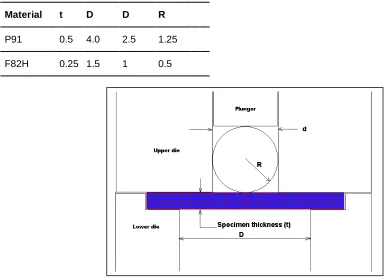
Experimental setup.The schematic diagram of the experimental set up of the small punch testing and typical Finite element mesh is shown in Fig.1.The specimen is kept between upper and lower die. Upper die is provided with the central hole for ball and plunger movement. The upper and lower die centres are aligned concentrically to specimen centre. The experimental set up parameters are given in table 2.The lower die hole diameter D, ball radius R, thickness of the specimen t, upper die hole diameter d. In actual experimental setup Jia (2003), Milicka (2006), a fillet radius of 0.2 mm is provided for lower die, which is not considered in our study.
Table.2
.Small punch Test setup parameters (all dimensions are in mm)
Material t D D R
P91 0.5 4.0 2.5 1.25
F82H 0.25 1.5 1 0.5
Fig.1.Schematic diagram of Small punch experimental set up Material Cr C Mo Mn Ni V Nb N W Ta Si
P91 8.5 0.1 0.88 0.4 0.1 0.23 0.1 0.045 - - -
F82H* 7.65 0.09 - 0.16 - 0.16 - - 2 0.02 0.11
4
NUMERICAL SIMULATION OF SMALL PUNCH TESTS
For simulating SPT, established GTN model is utilized. The ductile damage model employs a yield potential represented in terms of a single damage quantity i.e. the void volume fraction (f).the GTN model initially proposed by Gurson A.L (1977) and later modified by Tvergaard V(1981,1984). and Needleman A. In house code MADAM incorporated with the GTN model is used.
4.1 Finite element modelling.
In the present work systematic Finite element (FE) analysis is performed. Micro mechanical parameters are obtained by simulation of SPT. The small punch specimen of diameter 3mm with thickness of 0.25mm is used for F82H material and 8 mm diameter with 0.5mm thickness for P91 material. Descritization (FE model) of the geometry is done with Axi-symmetric 8 node quadrilateral elements. The FE model of P91 consists of 96 elements with 345 nodes and F82H consists of 80 elements with 380 nodes. The mesh size of 0.0625mm for F82H and 0.125mm for P91 is used. Modelling and simulation is carried out using in house FE package MADAM (MAterial DAmage Modelling). In Fig.1 schematic FE model of the SPT specimen for F82H is shown. A relative sliding between ball and specimen is taken into consideration.
Table 3.
Elastic material parameters.
Material E(N/mm2) YS(N/mm2)
P91 2.0E5 0.3 385
F82H-Unirr 2.07E5 0.33 532
F82H-Irr 2.07E5 0.33 607*
* Yield strength determined from the SPT calibration
4.2 Validation of FE model with P91 material
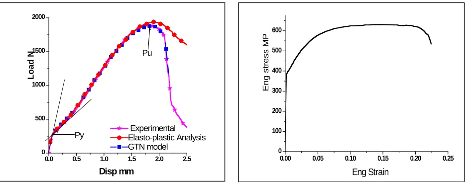
Validation of the FE model is done by comparing numerical results with that of experimental one for P91material. The load displacement data and stress strain data used for simulation are taken from paper Milicka (2006) and these are reproduced in Fig 2 and 3 respectively. The material properties Young’s modulus, Yield strength and poison’s ratio are taken as given in table 3.Parametric study is carried out by varying the friction factor between ball and specimen. An appropriate friction factor (f) of 0.045 is obtained by matching the experimental load displacement curve of SPT up to peak load (Pu), see Fig 2. This f=0.045 is used as one of the input to damage analysis. The damage parameters for the material are determined by varying the initial void volume fraction (f0) and void nucleation rate (fn) in damage analysis. The appropriate f0=0.0008 and fn=0.005 values are found by comparing the slope of simulation and SP test load displacement curve beyond the displacement at Pu, see Fig 2.
Fig.2.Load displacement curves for P91 material. Fig.3 Eng stress strain curve for material P91.
4.3 Analysis of Unirradiated F82H material.
0.0 0.5 1.0 1.5 2.0 2.5
0 500 1000 1500 2000
Pu
Py ExperimentalElasto-plastic Analysis
GTN model
L
o
a
d
N
Disp mm
0.00 0.05 0.10 0.15 0.20 0.25
0 100 200 300 400 500 600
Eng stress MP
The methodology described in section 4.2 is used for un-irradiated F82H material to determine the friction factor and damage parameters. The elastic material properties and stress strain data are taken from Spatig (2004) for the analysis. The elastic material properties are tabulated in table 3. A friction factor of f=0.075 is obtained. The damage parameters used in the analysis are tabulated in table 4.The deformed shape and contour plot of von mises stress for SP specimen is shown in Fig 4.
Fig.4 Deformed shape and contour plot of Von mises stress
The load displacement data of elasto-plastic and damage analysis for unirradiated material are
shown in Fig 5.
Fig.5.Load displacement curve for unirradiated F82H material
Fig.6. Schematic diagram of two types of hardening
4.3 Analysis of Irradiated F82H material.
The stress strain data are generated by using the guidelines given in Tanguy (2006) for irradiated material.
0.0 0.2 0.4 0.6 0.8 1.0 1.2
0 50 100 150 200 250 300 350 400
Experimental Elastic plastic GTN
L
o
a
d
N
Disp mm
0.00 0.02 0.04 0.06 0.08 0.10
500 600 700
!YS
!YS
Eng
stress
Eng strain
Two types of irradiation Induced hardening is found in literature and are schematically represented in Fig 6.These hardening behaviours can be approximated by two hypotheses. In the first hypothesis (H1), the whole stress strain curve of the unirradiated material is shifted to higher stress values by YS (keeping the strain hardening rate constant) [Margolin (2003), Al Mundheri (1989)]. This case is observed experimentally for the ferritic alloys irradiated at 288 0C by electron irradiation [Farrell(2000)].In second hypothesis (H2), the yield stress is increased by Y S where as the UTS is kept constant ( this makes hardening rate substantially lower than the unirradiated condition). This case is reported for steels (ferritic, martensitic) subjected to neutron irradiation at low temperatures (≤ 200 0C) [Byun (2004)].It is also suggested that neutron irradiation has a similar effect as a plastic pre strain on strain hardening [Byun (2004)].
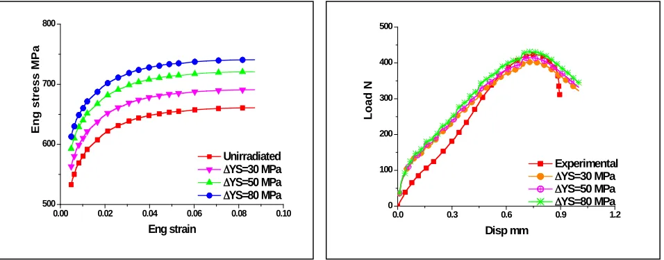
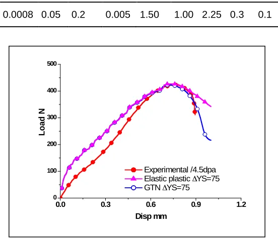
The parametric study is carried out by varying YS from 30 to 80 MPa. The engineering stress strain data for various YS according to hypotheses are shown in Fig 7 and 9 respectively. The SPT simulation results for various shifts in Y S are shown in fig 8 and 10 respectively. The appropriate YS for irradiated material is found by comparing the peak load of the experimental result with simulation result. The simulation result corresponding to 75MPa shift in YS from hypothesis H1 is close to the experimental load displacement curve of the irradiated material. This is shown separately in Fig 11.
Fig 7. Stress strain curves according to H1. Fig 8.Load displacement curves corresponding to H1
Fig.9. Stress strain curves according to H2. Fig 10.Load displacement curves corresponding to H2
Table 4.
Damage parameters used in present study.
f0 fc ff fn q1 q2 q3 n Sn
0.00 0.02 0.04 0.06 0.08 0.10
500 600 700 Eng stress MPa Eng strain Un Irradiated !YS=30 !YS=50 !YS=75
0.0 0.2 0.4 0.6 0.8 1.0
0 100 200 300 400 500 Experimental Irradiated
!YS=30 MPa
!YS=50 MPa
!YS=80 MPa
LOAD
N
Disp mm
0.0 0.3 0.6 0.9 1.2
0 100 200 300 400 500 Experimental
!YS=30 MPa
!YS=50 MPa
!YS=80 MPa
L o a d N Disp mm
0.00 0.02 0.04 0.06 0.08 0.10
500 600 700 800
Unirradiated
!YS=30 MPa
!YS=50 MPa
!YS=80 MPa
Eng
stress
MPa
0.0008 0.05 0.2 0.005 1.50 1.00 2.25 0.3 0.1
Fig 11.Load displacement curves for irradiated material.
5
DISCUSSION
The simulated load displacement results along with the experimental ones are shown in Fig 3 and 5 for unirradiated materials and the Fig 11 shows for irradiated material. From the experimental data it is seen that due to irradiation the peak load of the SP test increases and the displacement at peak load decreases. The increase in peak load corresponds to increase in UTS by considering the correlation in Milicka (2006). From the fig. 5 and 11 it can be seen that, in the elastic bending region the simulation results diverge from experimental result and, between yield load to peak load the simulation result converge to experimental result. This pattern is observed in both irradiated and unirradiated F82H material. But this is not observed in the simulation of P91 material. This may be due to two reasons, 1] heat treatment conditions of the F82H material (refer Table1), 2] Presence of the machine compliance in measurements of load displacement data of the F82H material.
6
CONCLUSION
The finite element model of the small ball punch test is validated with P91 steel. For F82H material, damage parameters and stress strain data are ascertained by comparing the experimental load displacement curve with corresponding simulated load displacement curves. From the results, it can be concluded that the methodology mentioned in this paper can be successfully utilised in the determination of the damage parameters and stress strain data of the irradiated materials. The present technique is capable of estimating the YS and flow stress curve with reasonable accuracy.
REFERENCES
Al Mundheri M, Soulat P, Pineau A.1989, Irradiation embrittlement of a low alloy steel interpreted in terms of local approach of cleavage fracture.Fatigue fracture Engineering Materials structure.Vol.12:1, P 19-30. Byun T.S., Farrell K.2004,I rradaition hardening behaviour of poly crystalline metals after low temperature irradiation Journal of Nuclear Materials,Vol.326.P 86-96.
Byun T, Farrell K,2004, Plastic instability in polycrystalline metals after low temperature irradiation.Act Materialia. Vol.52.P 1597-1608.
0.0 0.3 0.6 0.9 1.2
0 100 200 300 400 500
L
o
a
d
N
Disp mm
Experimental /4.5dpa
Elastic plastic !YS=75
Chang Y-S, Kim J-M, Choi J-B, Kim Y-J, Kim M-c, Lee B-S.2008, Derivation of ductile fracture resistance by use of small punch specimens, Engineering fracture mechanics,Vol.75.P 3413-3427.
Campitelli E.N,Spatig P,Bonade R,Hoffelner W,Victoria M,2004, Journal of Nuclear Materials, Vol.335.P 366-378.
Campitelli E.N, Spatig P, Bertsch J, Hellwig C, 2005, Assessment of irradiation-hardening on Eurofer97’ and Zircaloy 2 with punch tests and finite-element modeling,Materials Science and Engineering A, Vol. 400–401.P.386–392
Farrell K., Byun T.S.2000, Hardening of ferritic alloys at 288C by electron irradiation, Journal of Nuclear Materials. Vol.279.P 77-83.
Gurson A.L, 1977, Continuum of ductile rupture by void nucleation and growth: Part I––Yield criteria and flow rules for porous ductile media. Journal of Engineering Materials Technology .Vol.99.P 2–55
Jia X,Dai Y.2003,Small punch test on martensitic/ferritic steels F82H,T91 and Optimax-A irradiated SINQ Target-3, Journal of Nuclear Materials,Vol.323.P 360-367.
Karel Milicka, Ferdinand Dobes, 2006, Small punch testing of P91 steel, Int. J. Pressure vessel and piping, Vol.83.P 625-634.
Kim M-C.,Yong Jun Oh,Lee B-S,2005,Evalutaion of ductile brittle transition temperature before and after neutron irradiation for RPV steels using small punch tests, Nuclear Engineering Design,Vol.235.P 1799-1805.
Margolin B, Gulenko A, Nokolaev V, Ryadkov L, 2003, A new engineering method for prediction of fracture toughness temperature dependence for RPV steels. International journal of pressure vessel and piping, Vol.80.P 817-829.
Spatig P., Bonade R., Hoffelner W., Victoria M.2004, Assesment of constitutive properties from small ball punch test: experiment and modeling, Journal of Nuclear Materials,Vol.335.P 366-378.
Tanguy B, Bouchet C, Bugat S, Benson J.2006,Local approach to fracture based prediction of T56j and Tkic100 shifts due to irradiation for an A508 Pressure vessel steel, Engineering Fracture Mechanics, Vol.73.P 191-206.
Tvergaard V, 1981, Influence of voids on shear band instabilities under plane strain conditions. International Journal of Fracture Mechanics. Vol.17:3.P.89–407.
Tvergaard V, Needleman A, 1984, Analysis of the cup-cone fracture in a round tensile bar. Acta Mech Sinica Vol.32:1.P.157–69.
Wang Z-X, et al., Small punch testing for assessing the fracture properties of the reactor vessel steel with different thickness.Nuc.Eng.Des (2008), doi:10.1016/j.nucengdes.2008.07.013.