20th International Conference on Structural Mechanics in Reactor Technology (SMiRT 20) Espoo, Finland, August 9-14, 2009 SMiRT 20-Division 5, Paper 1784
COMPARISON OF APPROXIMATE METHODS FOR SLIDING
AND ROCKING EVALUATION OF UNANCHORED PLATFORMS
Sohrab Esfandiari
a), Christopher Wandell
b)a) ENOVA Engineering Services, Walnut Creek, California, USA
b) Arizona Public Service Company, Tonopah, Arizona, USA
Keywords: Sliding, Rocking, Tip-over, Overturning, Stability, Seismic II over I interaction
1 ABSTRACT
There are many unanchored structures in use in commercial nuclear power plants. Most widely used are scaffolding frames in support of plant outages. In general, unanchored structures are not safety related and are of no safety concern unless Seismic Category 1 SSCs (Structures, Systems, or Components) are present in their zone of influence. For such situations, the stability of the unanchored bodies under a seismic event must be checked to ensure that adverse interaction between the source (the unanchored structure) and safety related targets, does not occur. This phenomenon is commonly referred to as “Seismic II over I” interaction, “Seismic separation” or “Zone of influence” interaction. The issues of concern for seismic stability of an unanchored body are the extent that it could slide, as well as the maximum angle of rotation associated with rocking of the body and potential for tip-over (i.e., instability).
At the Palo Verde Nuclear Generating Station (PVNGS), the Spent Fuel Dry Cask loading operation in the Fuel Handling building utilizes 3 separate platforms which are designed to provide support for personnel and equipment. These platforms are portable and are moved by the building crane into position during a Cask loading campaign. When not in use, these platforms are stored in an area, which are within the zone of influence of safety related SSCs. As such, platform stability under the plant Safe Shutdown Earthquake (SSE) seismic event must be ensured. Therefore as a prudent part of the design process, the sliding and rocking of these platforms is checked to ensure that adverse interactions are avoided and that sufficient clearance is provided in their permanent storage configuration.
The stability evaluation of unanchored bodies is a non-linear phenomenon. This problem can only be accurately solved by performing non-linear time history analysis of the platform allowing for proper geometric non-linearity at the contact interface. However, this solution requires the development of multiple time histories which typically do not exist for in-structure elevations of nuclear plant structures. As such, most engineers use the approximate sliding method developed by Newmark for sliding of structures, as well as approximate Energy Balance method for evaluation of rocking and tip-over of unanchored bodies. Recently a newer more accurate method which utilizes in-structure spectra as the source of seismic demand was published in ASCE/SEI 43-05. Since this approach utilizes plant spectra, it presents a practical alternative to time history analysis for performing such stability evaluations.
2 INTRODUCTION
At the Palo Verde Nuclear Generating Station (PVNGS), the Spent Fuel Dry Cask loading operation in the Fuel Handling building utilizes 3 separate platforms which are designed to provide support for personnel and equipment. These platforms are portable and are moved by the building crane into position during a Cask loading campaign. When not in use, these platforms are stored in an area which is within the zone of influence of safety related systems. As such, their stability under the plant SSE seismic event must be ensured.
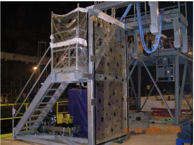
The focus of this paper is to show the analytical methodology and results for performing seismic sliding and overturning stability evaluations for one of these platforms. The frame chosen is designated as the “Stairway Platform” and is shown in Figure 1. The Seismic stability evaluation is performed using the methodology of ASCE /SEI 43-05 for sliding and rocking of unanchored rigid bodies. The same platform is evaluated using the traditional Newmark method for sliding, and the traditional Energy Balance approach for rocking/overturning. Results using both approaches are compared for both sliding and rocking, and conclusions are presented.
Figure 1: Stairway Platform at PVNGS
3 ANALYTICAL METHODOLOGY
The methodology followed is that of ASCE/SEI 43-05 Standard for “Seismic Design Criteria for Structures, Systems, and Components in Nuclear Facilities” (Ref. 1). Specifically, the sliding and rocking of unanchored bodies of Section 7 and Appendix A of this ASCE Standard are used which are also referred to as the “Reserve Energy” approach. These methods provide “conservatively biased estimates” of sliding displacements and “best-estimate” maximum rocking angles (and thus displacements due to rocking) of unanchored bodies.
3.1 Sliding Calculation (based on ASCE 43-05 methodology) First, an effective coefficient of friction, µe, is defined as:
where µ is the coefficient of sliding friction taken conservatively as 0.3 for steel on concrete (dry and clean conditions) and Av is the peak vertical acceleration, taken as 0.52g corresponding to the 10% damped spectral acceleration at the fundamental vertical frequency of this platform. Next, a sliding coefficient, cs, is defined as:
cS= 2µeg (2)
Where g is the acceleration due to gravity. The conservatively biased “best estimate” of sliding distance, s, is given by:
(
)
22 es
S s
f c ! " =
(3)
Where, fes is the lowest natural frequency at which the horizontal 10% damped vector spectral acceleration SAVH equals CS, and:
[
2]
122 2
1 0.16 H
H
VH SA SA
SA = +
(4)
Where, SAH1 and SAH2 are the 10% damped spectral accelerations for each of the two
orthogonal horizontal components, and SAH1 is the larger of the two. Considering the spectral
accelerations for this location and after plugging in the formulae for this platform, feS =0.88 Hz, and based on the above approach the conservatively biased estimate of sliding displacement is predicted as !s = 6.00 .
3.2
Sliding Calculation (based on Newmark Approaches)
The same problem is solved using both the “original” (Ref. 2) and the later “modified” (Ref. 3) Newmark approaches, denoted as Newmark I and Newmark II to be consistent with the terminology used in Ref. 1. Using Newmark I and Newmark II approaches, the sliding displacement is given by the following equations:
s = V 2
/2gµe [1 - µeg/Ah] Newmark I equation (5) s = 2V
2
/gµe [1 - µeg/Ah] 2
Newmark II equation (6)
Inserting the relevant parameters into these equations, one gets the following estimates of sliding displacements for the subject platform:
s = 2.64" Newmark I equation s = 8.69" Newmark II equation
3.3 Rocking Calculation (based on ASCE 43-05 methodology)
Figure 2 shows the unanchored body during postulated rocking motion.
Figure 2: Rigid Body Rocking Definitions (Ref. 1, Figure A-1) First instability angle, α, is defined by
α = arctan (a) a = b/h where:
b = minimum horizontal distance from the edge of the body to the CG h = center of gravity height
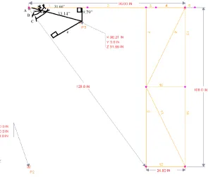
For the subject platform, the center of gravity height is h = 94.89". The shortest “b” distance to the nearest edge for rocking is 9.79" as shown in Figure 3 below which is the plan view of a math model of the platform.
Note that the center of gravity height, h, and the rotation arm, b, are with respect to the centerline of the structural elements. In order to arrive at the actual distances to the edge of the base members, ½ of the member dimensions (Tube Steel 6 x 6) were added to these values, thus:
h = 94.89+6/2=97.89" b = 9.79+6/2=12.79"
resulting in an instability angle, α = 7.45 degrees. The rotational distance R, as defined in Figure 2 is thus calculated to be 98.72".
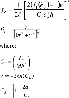
To perform the rocking calculations per methodology of ASCE 43-05, 1st effective rocking frequency fe corresponding to any θo and effective damping βeis calculated per the following
formulas:
( )
(
)
122 1
1
2
2
1
!
"
#
$
%
&
'
=
h
è
C
g
è
f
!
f
o I o e (7)[
2 2]
124" ! ! # + = e (8) where: ! " # $ % & = 2 Mh I C B I (9) ) (
2lnCR
! = " (10) ! " # $ % & ' = I R C a C 2 2 1 (11)
in which IB is the mass moment of inertia of the rigid body about the edge B or center of
rotation (see Figure 2), and M is the rigid body vertical resisting mass. For the situation where the center-of-gravity is at the center of the rigid body and the lateral inertial mass ML and vertical resisting mass M are equal and uniformly distributed:
( )
21 3 4
a
CI ! +
" # $ % & = (12)
Plugging the appropriate numbers for this platform, one arrives at βe = 0.0081 for effective damping, thus respective demand and capacity against rocking must be extracted from a 0.8% damped spectra. This is performed by interpolation between available 0.5% and 1.0% damped spectra for the storage location of this platform.
Next the rotation angle, θo, is calculated such that horizontal spectral acceleration capacity,
SAHCAP, is first equal to the input spectral acceleration demand, SAHDEM defined at effective
frequency, fe and effective damping, βe:
SAHCAP = SAHDEM
1 ) 2 ( 2 2 + ! " # $ % & = em I om !f g h C a è (13)
And SAHCAP for θom is computed from the following equations:
( )
(
)
o V H o CAPè
F
F
è
f
g
SAH
=
2
1!
1
(14) ) sin( ) ( ) cos( ) (
1 èo èo a èo
f = + (15)
Mh h M
F L L
H = (16) 2 1 2
)
(
)
(
1
!
!
"
#
$
$
%
&
''
(
)
**
+
,
+
=
SAH
F
SAV
a
F
H V (17)where SAV and SAH are vertical and horizontal spectral accelerations determined at the effective rocking frequency (fe) and effective damping (βe) The factor FH corrects for the difference between lateral inertial mass (ML) and vertical resisting mass (M) and hL is the center of gravity height for the lateral inertial mass.
For small θo angles less than 0.4 radian (16.2 deg), Reference 1 recommends the following simplifications in solution of the above equations:
( )
(
)
) 2 ( 1 1 o o o è a è èf ! " !
(18)
)
2
(
o V HCAP
a
è
F
F
g
SAH
"
!
(19) For the staircase platform, the following spectral accelerations are used:
SAV= 1.95 g (Vertical component) SAH=3.33 g (NS component)
The above equations must be solved by iteration searching for a rotation angle at which
SAHCAP = SAHDEM. Note that if SAHDEM > SAHCAP for rotation angles up to the instability angle,
then the body is considered unstable and tip-over is predicted under the postulated seismic demand. For the Stairway Platform, with a stability angle of 7.45 deg, SAHDEM = 0.2g which is still greater than SAHCAP= 0.13g, thus concluding that this platform is not stable about the edge with the shortest distance from projection of CG location on plan view.
3.4 Rocking Calculation (based on Energy Balance methodology)
The traditional “Energy Balance” approach (Ref. 4) computes the vertical uplift of the CG of the unanchored structure by equating the potential energy with the kinetic energy imposed as a result of the seismic demand. The energy required to uplift the CG of a structure of mass “m” by a distance h is given by:
Eo = mg h (20)
The kinetic energy provided by the seismic demand is given by:
Es = ½ m (Vh2 + Vv2) (21)
Where Vh is the horizontal velocity in the direction of rocking and Vv is the vertical velocity.
The factor of safety against overturning is thus given by: Eo/Es =
)
V
(V
)
(
2
2 v 2
h
+
h
g
!
(22)
For the Staircase Platform, h = 0.83", Vh = 1.99 ft/sec. and Vv = 0.69 ft/sec., resulting in the ratio
of Eo/Es = 1.0, thus indicating that the platform reaches the onset of instability angle = 7.45°,
when comparing the demand kinetic energy vs. the resistance potential energy.
Note that the methodology of ASCE 43-05 for the same platform indicates that at the onset of instability (i.e., stability angle = 7.45°) the seismic demand is still greater than seismic capacity, thus predicting that the platform is not stable against rocking for the direction studied and will tip-over.
4 RESULTS
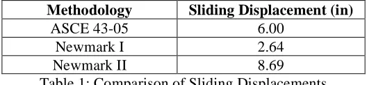
Table 1 below provides a comparison of conservatively biased sliding displacement as predicted by the ASCE 43-05 method vs. traditional Newmark I and II methods for the subject Stairway Platform:
Methodology Sliding Displacement (in)
ASCE 43-05 6.00
Newmark I 2.64
Newmark II 8.69
Table 1: Comparison of Sliding Displacements
5 CONCLUSIONS
Reference 1 provides a newer more reliable methodology for the prediction of sliding displacements and rocking angles of unanchored rigid bodies which is based on plant response spectra defining seismic demand. The methodology of Reference 1, also called the “Reserve Energy” approach has been benchmarked against more accurate, time history non-linear analyses for the prediction of sliding and rocking of unanchored bodies. The Newmark I method for predication of sliding displacement, and the traditional energy balance approach for prediction of rocking and tip-over of unanchored bodies both tend to under-estimate the results for this application and are thus on the non-conservative side. The Newmark II method for prediction of sliding displacement for this application tends to over-estimate the results compared to the methodology of Reference 1, however this is expected at lower friction coefficients. Reference 1 concludes that at higher friction coefficients, even Newmark II approach would produce results which would be on the non-conservative side compared to Ref. 1 approach.
Based on the results of the Stairway Platform analyses, the following conclusions are reached:
1. At low coefficients of friction such as that used in this platform analysis, the Newmark I method under-estimates the corresponding ASCE 43-05 sliding displacement by 55%, whereas the Newmark II method over-estimates the ASCE 43-05 sliding displacement by 45%. This trend is consistent with that shown in Appendix B of Reference 1 for lower friction coefficients. For higher friction coefficients, Ref. 1 indicates that both Newmark methods will tend to under-estimate the sliding displacement compared to the ASCE 43-05 approach.
2. For rocking and tip-over analysis, the traditional “Energy Balance” approach concludes that the subject frame is stable against tip-over with a safety factor of 1.0 (meaning it is at the onset of instability), whereas the more detailed approach of Ref. 1 indicates that the subject platform is not stable given the seismic demand and will likely tip-over about the nearest edge. At the onset of instability (i.e., stability angle) the reserve energy approach predicts SAHDEM = 0.2g vs. SAHCAP = 0.13g indicating that the seismic demand is greater than rocking capacity of the frame. Thus the conclusion reached using the traditional “Energy Balance” approach tends to be on the non-conservative side.
6 REFERENCES
[1] – ASCE Standard 43-05, “Seismic Design Criteria for Structures, Systems, and Components in Nuclear Facilities.
[2] – Newmark, N.M. (1965). “Effects of earthquakes on dams and embankments.” Fifth Rankine Lecture, Geotechnique.
[3] – Newmark, N.M., and Rosenblueth, E. (1971). “Fundamental of earthquake engineering.” Prentice-Hall, Englewood Cliffs, N.J.