Computer simulation study of pattern transfer in
AB
diblock copolymer
film adsorbed on a heterogeneous surface
A. Jayaraman, C. K. Hall,a兲 and J. Genzer
Department of Chemical and Biomolecular Engineering, North Carolina State University, College of Engineering 1, Box 7905, 911 Partners Way, Raleigh, North Carolina 27695
共Received 1 April 2005; accepted 3 August 2005; published online 23 September 2005兲
In this work we investigate how a pattern imposed in a copolymer film at a certain distance from the surface propagates through the film onto an adsorbing heterogeneous surface. We bias the copolymer film to adopt a specified target pattern and then use simulation to design a surface pattern that helps the adsorbed film to maintain that target pattern. We examine the effect of varying the copolymer chain length, the size of the target pattern, and the distance from the surface where the target pattern is applied,z
⬘
, on the extent of pattern transfer. For each chain length, target pattern, andz⬘
we compare the energy of the system when a pattern is applied in the bulk to the energy when no pattern is applied in order to understand why a certain pattern size is transferred to the surface with higher fidelity than the others. At constant chain length, pattern transfer is best when the pattern size brings the energy of the system close to the energy when no pattern is applied. At constant pattern size, pattern transfer is best in the systems with longer chains. This is because longer chains are more likely to adsorb as brushes and loops which then helps transfer the pattern through the adsorbed film down to the surface. ©2005 American Institute of Physics.关DOI:10.1063/1.2043048兴
I. INTRODUCTION
Adsorption of polymers on solid surfaces plays an im-portant role in many technological and scientific applications including adhesion,1 chromatography,2 nanoscale patterning,3biomedical implant modification,4,5etc. In order to exploit these applications, it is important to understand how polymers organize in the vicinity of surfaces. Most sur-faces in nature are physically or/and chemically heteroge-neous and many polymers are typically composed of two or more types of monomers arranged in a specified sequence
共diblock, triblock, or alternating copolymers兲 or a random sequence. Therefore, studying the adsorption of heteropoly-mers on heterogeneous surfaces is useful in describing real world situations.
There have been many experimental efforts aimed at un-derstanding how chemically heterogeneous patterns on sur-faces induce ordering in adsorbed block copolymers.6–12 Rockford et al.8,9 studied adsorption of polystyrene-poly共methyl methacrylate兲 共PS-PMMA兲 block copolymers on surfaces containing alternating stripes of gold and silicon oxide. The PS-PMMA block copolymers formed ordered lamellar microdomains oriented perpendicular to the surface with the PS domains covering the gold stripes and the PMMA domains covering the silicon oxide stripes. Rockford et al.8,9and Kimet al.10 also found that the influence of the surface pattern on the lamellar ordering and orientation of adsorbed polymers is strongly dependent on the degree of commensurability between the polymer length and the stripe widths. Yanget al.11found that when the width of the surface pattern is much greater than the bulk lamellar period of the
block copolymer then the lamellae orient parallel to the sur-face and replicate the underlying substrate pattern into the bulk. However, when the width of the surface pattern is com-mensurate with the bulk lamellar period of the block copoly-mer, the lamellae orient perpendicular to the substrate. Heier et al.12investigated the behavior of symmetric poly共 styrene-2-vinylpyridine兲 共PS-PVP兲 block copolymer thin films on patterned substrates formed using microcontact printing that had alternating stripes of H3C-and HO-terminated self-assembled monolayers共SAMs兲. They found that the energy required to form islands of PS-PVP is different for each sur-face stripe. Since the H3C-terminated SAM domains are en-ergetically more favorable for the formation of islands than the HO-terminated SAM domains are, PS-PVP forms islands over the H3C-terminated SAM domains.
In addition to the experimental work mentioned above, theory and simulation have been used to shed light on the organization of block copolymer bulk on patterned surfaces.13–24 Petera and Muthukumar used mean-field theory13 and self-consistent-field theory14 to show that the orientation of the lamellae formed by diblock copolymer de-pends on the ratio of the substrate pattern period共L兲and the radius of gyration of the diblock copolymer 共Rg兲in a
disor-dered melt. WhenRg/L⬃ 冑共2冑3兲/ 2, the surface pattern
pe-riod and the lamellar pepe-riod are commensurate and the lamellae align perpendicular to the surface. Genzer used a three-dimensional 共3D兲 self-consistent-field model to inves-tigate the adsorption of copolymers from a copolymer-homopolymer mixture15–17 onto a heterogeneous surface composed of two chemically different regions arranged ei-ther in checkerboard or random patterns. He demonstrated that if heteropolymers recognize the patterns on the hetero-a兲Electronic mail: [email protected]
geneous surface, they can transcribe the pattern from the surface into three dimensions. Semler and Genzer used the bond fluctuation model and Monte Carlo simulations to study the effect of domain size18 and interaction potential19 on adsorption of diblock and alternating copolymers on chemically heterogeneous surfaces. The block copolymers recognize the surface pattern and transfer it to the bulk if the size of the adsorbing surface domain is commensurate with the parallel component of the radius of gyration of the block copolymers. The alternating copolymers recognize chemical patterns of sizes much smaller than the Rg,储, the radius of
gyration parallel to the surface of the copolymer. As the strength of attraction between the block copolymer and sur-face increases, the extent to which the pattern is transferred to the bulk remains unaffected. As the strength of attraction between the alternating copolymer and surface increases, the pattern transferred into the bulk at increasing distances from the surface resembles an inverted surface pattern. Jayaraman et al.developed a simulation method recently to design sur-faces for recognizing specific monomer sequences in copolymers.20 For copolymers with less blocky sequences, the designed surfaces recognize the correct sequence well when the segment-surface interactions dominate over the in-tersegment interactions. For copolymers with more blocky sequences, recognition is good when the segment-surface in-teractions are only slightly stronger than the intersegment interactions. Using a theoretical model, Kriksin et al. also found that when copolymers made of short blocks adsorb on heterogeneous surfaces, marked pattern recognition is pos-sible at high polymer/surface attraction.21
All of the work done so far has dealt with understanding how the pattern on the heterogeneous surface gets recognized and propagates through the copolymer film. Here we attempt to understand how a pattern applied in the copolymer film at a certain distance from the surface propagates through the adsorbed film onto the adsorbing heterogeneous surface. Ul-timately we intend to determine what surface pattern is re-quired to induce a desired pattern in the adsorbed polymer film.
We use lattice Monte Carlo simulations to explore how the length of the diblock copolymer, size of the patterns
共checkerboard兲, and the distance from the surface where the pattern originally exists affect the extent of pattern transfer through the adsorbed layers to the surface. A study of how a diblock copolymer film transfers patterns with sizes on the order of the copolymer length scale through the adsorbed layers could help us understand how to form unique nanos-cale structures which in turn would be useful in nanolithog-raphy and the development of photonic devices.6,7
Our system consists of symmetric AB diblock copoly-mers adsorbing onto a flat, chemically heterogeneous surface containing two types of sites: 1 and 2. Our approach com-prises several steps. First we bias the copolymer bulk to adopt a target pattern at a specified distance from the surface. Then we let the surface reorganize itself in response to the pattern in the copolymer bulk. We achieve this by switching the identities of sites on the surface and performing chain moves during the simulation with an acceptance criterion that minimizes the energy and biases the adsorbed layers to
maintain the target pattern at the desired distance from the surface. We consider an attractive potential between like co-polymer segments 共A-A andB-B兲and an attractive potential between the surface sites and copolymer segments共A-1 and B-2兲. These potentials favor the transfer of the target pattern through the different adsorbed layers to the surface and help the surface to adopt a pattern commensurate to the target pattern. The more the surface resembles the target pattern, the higher the extent of pattern transfer through the adsorbed layers. We study three different chain lengths 共12, 18, and 24兲and three different pattern sizes共checkerboard pattern of sizes 6⫻6, 12⫻12, and 24⫻24兲. The pattern is applied at three different distances from the surface 共z
⬘
= 1, 2, and 3兲. We also compare each of these systems with the case when no pattern is applied while all other parameters are main-tained the same. When no pattern is applied in the adsorbed layers, the copolymer chains are free to attain their natural conformations. We do this comparison to understand why a certain pattern size gets transferred to the surface better than the other patterns.The highlights of our results are the following. As we increase the distance from the surface where the target pat-tern is applied, the patpat-tern transfer to the surface decreases for all patterns and all chain lengths. For a constant pattern size, the pattern transfer to the surface increases as the chain length increases. For a constant chain length, the patterns that help the chains attain energies close to the case when no pattern is applied get transferred to the surface well. To test if we can use the designed surfaces from this stage and induce the target pattern back in the adsorbed layers of a new co-polymer bulk, in the next stage we let a new coco-polymer bulk in a random configuration adsorb onto each of these “de-signed” surfaces. For all the pattern sizes and chain lengths considered, we do not see the transfer of the surface pattern back to the adsorbed layers and the copolymer chains form other energetically favorable patterns.
Section II introduces the simulation technique. Section III describes the application of this method to a system of block copolymers to learn how variations in copolymer chain length, target pattern size, and distance from the surface at which the pattern is applied affect the extent of pattern trans-fer from the bulk to the surface. A brief summary of our conclusions is given in Sec. IV.
II. MODEL AND METHODS
A. Simulation technique
A system of symmetric diblock copolymers is in contact with a heterogeneous surface located at z= 0. The diblock copolymers contain two types of segments:AandB. TheAB diblock copolymer chains are modeled as self-avoiding walks on a cubic lattice. The surface contains two types of sites, 1 and 2. The values of the segment-segment interaction potentials,⑀AA,⑀BB, and⑀AB, and the segment-surface
inter-action potential,⑀A1,⑀B1,⑀A2, and⑀B2, are assigned such that
⑀AA, ⑀BB, ⑀A1, and ⑀B2 are all negative 共implying attractive potentials兲and⑀AB,⑀A2, and⑀B1are zero. Attractive segment-surface interactions,⑀A1and⑀B2, cause the chains to adsorb on the surface. Attractive segment-segment interactions,⑀AA
and ⑀BB, cause the adsorbed chains to pull other chains
to-wards themselves leading to dense adsorbed layers near the surface. The segment-segment interaction potential is short ranged; it only affects nonbonded nearest neighbors. The segment-surface interaction potential is also short ranged, acting only between the sites on the adsorbing surface
共z= 0 plane兲and the segments that are on the plane adjacent to the adsorbing surface共z= 1 plane兲.
The volume fraction ⌽ of the AB diblock copolymer segments in the simulation box is 0.35. The interaction potentials are taken to be ⑀A1=⑀B2= −1.33kT and
⑀AA=⑀BB= −0.6kT. These interaction potentials were chosen
to be strong enough to cause the chains to adsorb onto the surface yet weak enough to avoid ordering or segregation of adsorbed chains. Having strong interaction between the co-polymer segments and the surface helps the coco-polymer chains to overcome the entropic penalty associated with coil formation during adsorption.
We design the surface by interchanging the positions of the surface sites over the course of the simulation. This is accomplished by generating moves that switch the identity of the different sites on the surface in response to a target func-tion that specifies the target pattern at a particular layer in the bulk. The target patterns in this paper are checkerboards of alternating regions of segments of type A and type B. In addition to the surface site switches, we move the segments on the chain using the standard chain moves: kink jump
共25%兲, crankshaft 共25%兲, and reptation 共50%兲. The type of move and chain and segment numbers along the chain are all picked randomly. In one Monte Carlo step 共MC step兲 we make Nchains⫻Nbeads trials, where Nchains is the number of chains in the simulation box and Nbeads is the number of segments in each chain. The acceptance criterion for the chain moves and the surface site switches are based on a modified Metropolis algorithm derived from reverse Monte Carlo acceptance criterion.25–27 The chain moves or site switches are accepted with a probabilityPaccgiven by
Pacc= min
冋
1,exp再
− 1kT
冋
共
Unew−Uold兲
+ 1
T⌫/T共⌫new−⌫old兲
册
冎
册
, 共1兲 where the subscript old signifies the present state of the system, the subscript new signifies the new state of system after the chain move or site switch has been attempted,Uis the energy of the system, ⌫is the deviation from the targetpattern共defined below兲,T is the temperature of the system, andT⌫ is an effective temperature that is used to weight the importance of target function fitting versus energy minimiza-tion. The energy U is calculated by summing up all of the nonbonded segment-segment and segment-surface interac-tions. The deviation from the target pattern ⌫ is calculated according to
⌫i=
兺
共x,y兲共x,y兲LxLy
, 共2兲
where 共x,y兲= 1 if the type of segment 共A or B兲 present at
共x,y兲 during the simulation does not match the type of seg-ment at共x,y兲in the target pattern, and 0 otherwise, andLxLy
is the area of the plane. The value of 共x,y兲 is calculated only for the layerz
⬘
where the target pattern is applied. The summation on 共x,y兲 is over all the 共x,y兲 coordinates in layerz⬘
and is a measure of how well layerz⬘
resembles the target pattern. We divide the summation by the area of the plane, LxLy, to scale the deviation between 0共no deviation兲and 1 共maximum deviation兲. Thus the term 共⌫new−⌫old兲 in the acceptance criterion 共1兲has the effect of minimizing the deviation from the target pattern. In our simulations, we chooseT⌫/T= 0.001 in order to weigh the energy minimiza-tion term ten times more than the target funcminimiza-tion fitting term, as the energy minimization term has a magnitude of the order of 100and the target fitting term has a value of the order of magnitude 10−4. When no target pattern is applied, the term denoting the deviation from target pattern⌫ is always zero. In that case, the acceptance criterion depends only on energy minimization and is given by
Pacc= min
冋
1,exp再
− 1kT共Unew−Uold兲
冎
册
. 共3兲 The simulation proceeds in the following manner. For convenience, the initial configuration of the surface is an alternating sequence of 1 and 2 sites. The initial configura-tion of the chains is obtained by first placing “head” seg-ments for all chains on random locations on the lattice. The second segments are placed on sites adjacent to the head segment on each of the chains, one by one. The third seg-ments are placed on sites next to the second segment, one at a time, and this is repeated until the chains are all grown to the desired length. During this process, if there is no vacant site for adding a segment onto one end of the chain, the segment is added to the other end of the chain. If adding the segment to either end fails共because there is no vacant site兲, then the chains are moved in the box 共using reptation, kink jump, and crankshaft moves兲 until a vacancy next to the chain in question is created.segment-surface interactions are switched on, the target pat-tern is applied at the specified distance from the surface, and the chain segments are subjected to the usual assortment of moves with the site switches still turned off. During this stage a fraction of the polymers adsorb on the initial surface. Once the fraction of adsorbed segments reaches a certain value 共2% of the segments in the system are adsorbed兲, the “production” stage or “design” stage starts. In the production stage the system goes through 8⫻106 MC steps, during which the standard chain moves are made, the target pattern is still applied at the specified distance from the surface, and the sites 1 and 2 are subjected to identity switches. We obtain data every 1000 MC steps and calculate the averages of the properties described in Sec. II B. We take averages obtained from ten trials and compute the standard deviations. At the end of the simulation we analyze the pattern of sites 1 and 2 on the designed surface to determine the extent to which the pattern has been transferred from the adsorbed layers to the surface.
For the simulation involving no target pattern there are two stages: initialization and equilibration. The initialization stage is the same as mentioned above. In the equilibration stage, the segment-segment and segment-surface interactions are switched on, the chain segments are subjected to the MC moves, and the site switches are turned on; the target pattern is not applied. At the end of the simulation the copolymers in the adsorbed layer attain their energetically favorable confor-mations.
B. Adsorption features
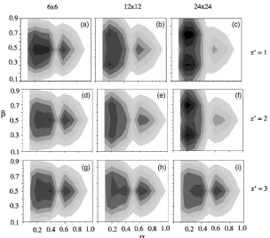
To characterize the adsorption process, we monitor vari-ous properties of the system as a function of the number of MC steps. These include the extent of adsorption, as mea-sured by the number of adsorbed segments of typeAandB, and the conformation of the chains near the surface during the adsorption process. The conformations of the adsorbed chains can be inferred from a contour plot depicting␣, the
fraction of chain length adsorbed, and , the ratio of the number of adsorbed segments on top of type 1 sites to the total number of adsorbed segments. An example of such a contour plot is given in Fig. 1. The plot in Fig. 1共a兲 repre-sents a system where most of the chains are adsorbed either in a flat conformation or in a loop conformation. The plot in Fig. 1共b兲 depicts a situation where most of the chains are adsorbed in brush conformations. The rationale for this iden-tification is the following. If a large fraction of chains are adsorbed in loop conformations, most of the segments will be extended from the surface with only a few segments lying in thez= 1 layer, implying that␣艋0.5; due to symmetry of the copolymers, equal numbers of adsorbed segments will lie on top of type 1 and type 2 sites, implying that = 0.5关 re-gion I in Fig. 1共a兲兴. If a large fraction of chains are adsorbed in flat conformations, most of the segments will lie in the z= 1 layer, implying that␣⬎0.5; due to the symmetry of the diblock copolymers, equal numbers of adsorbed segments will lie on top of type 1 and type 2 sites, implying that
= 0.5关region II in Fig. 1共a兲兴. If a large fraction of chains are adsorbed in brush conformations, a small section of each chain共all of the same segment type兲will be adsorbed on the surface共␣⬍0.5兲and the adsorbing segments of typesAand B will likely adsorb on their preferred sites 共since the segment-surface interactions⑀A1and⑀B2are attractive兲 mak-ingⰇ0.5关region III in Fig. 1共b兲兴orⰆ0.5关region IV in Fig. 1共b兲兴.
C. Calculation of the extent of pattern transfer
In order to quantify the extent of pattern transfer we introduce a pattern transfer parameter PTP.15–17 The PTP of the copolymer at height zfrom the surface is defined as
PTP共z兲= PTPA共z兲+ PTPB共z兲, 共4兲
FIG. 1. Contour plots for loop confor-mation共I兲, flat conformation共II兲, and brush conformations 共III and IV兲. ␣ denotes the fraction of chain length adsorbed.  denotes the ratio of the number of adsorbed segments on type 1 sites over the total number of ad-sorbed segments. The contour plots show the fraction of chains in the simulation box with the characteristics
PTPA共z兲=
兺
共xA,yA兲A共x,y,z兲−兺
共xB,yB兲A共x,y,z兲兺
共x,y兲A共x,y,z兲+兺
共x,y兲B共x,y,z兲, 共5兲
PTPB共z兲=
兺
共xB,yB兲B共x,y,z兲−兺
共xA,yA兲B共x,y,z兲兺
共x,y兲A共x,y,z兲+兺
共x,y兲B共x,y,z兲, 共6兲
where共xA,yA兲and共xB,yB兲are the x,y coordinates of theA
andBsegments, respectively, in the layer at which the target pattern is applied, andA共x,y,z兲 andB共x,y,z兲are the
av-erage volume fraction of segments AandB, respectively, at position共x,y,z兲. In Eq.共5兲the first term in the numerator is the sum of the volume fractions ofAsegments in thezplane, whose共x,y兲positions are the same as the positions of theA segments in the layer z
⬘
where the target pattern is applied. The second term in the numerator represents the sum of the volume fractions ofA segments, whose positions are differ-ent from the positions of the A segments in the layerz⬘
. In Eq. 共6兲 the first term in the numerator is the sum of the volume fractions of Bsegments in the zplane, whose posi-tions are the same as the posiposi-tions of theBsegments in the layerz⬘
. The second term in the numerator stands for the sum of the volume fractions ofBsegments in thez plane whose positions are different from the positions of theB segments in the layer z⬘
. The larger the value of the first terms in PTPA共z兲and PTPB共z兲, the better the match between thepat-tern on layer z and layer z
⬘
. The larger the value of the second terms in PTPA共z兲 and PTPB共z兲, the greater themis-match between the pattern on layerzand layerz
⬘
. Thus the numerators of PTPA共z兲 and PTPB共z兲 express how well thepattern formed by AandB segments, respectively, at a cer-tainzlayer resembles the pattern formed in the layerz
⬘
. The denominator is the sum of the volume fractions of all theA andBsegments in layerz. The value of PTP ranges between −1共complete negative pattern transfer兲and 1共complete posi-tive pattern transfer兲.When we apply the pattern atz
⬘
, we calculate the PTP at all layers below z⬘
to the surface. For example, when the pattern is applied at z⬘
= 3 we calculate PTP共z= 0兲, PTP共z= 1兲, and PTP共z= 2兲and, by doing so, we can observe the pattern transfer through the adsorbed layers.III. RESULTS AND DISCUSSION
When a target pattern is applied, the extent of pattern transfer is expected to be affected by the length of the co-polymers, the distance from the surface where the target pat-tern is applied, and the size of the target patpat-tern. In this section, we present and discuss the results from our simula-tions, showing the effect of variation in each of these param-eters on the extent of pattern transfer. We consider chains of length 12, 18, and 24; checkerboard patterns with sizes 6⫻6, 12⫻12, and 24⫻24; and target patterns at distances from the surface ofz
⬘
= 1,z⬘
= 2, and z⬘
= 3. For each of the chain lengths considered we compare the cases when a target pattern is applied to the case when no pattern is applied and the copolymers are free to attain their natural conformations. This helps us to共1兲understand why a certain target pattern istransferred to the surface better than other patterns and 共2兲 determine how the energy of the system, when the target pattern is applied, compares with the energy of the system when no pattern is applied. After the target pattern is trans-ferred to the surface and the surface pattern is designed, we adsorb a new copolymer film in a random configuration
共with the same chain length and interaction potentials兲onto the designed surface to test if the designed surface can trans-fer the pattern back through the adsorbed layers, inducing the target pattern at the desired distance from the surface.
A. Pattern transfer for different chain lengths
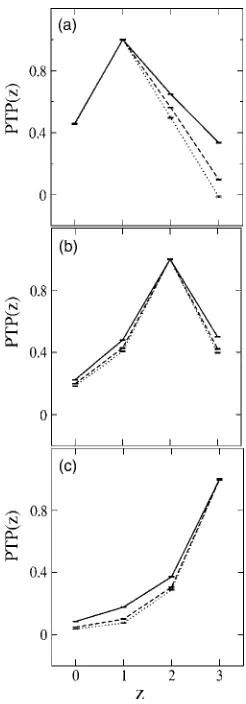
In Fig. 2 we plot the PTP as a function of distancezfrom the surface for chain length 12 when the pattern is applied at
共a兲z
⬘
= 1,共b兲 z⬘
= 2, and共c兲 z⬘
= 3 for different pattern sizes共6⫻6, 12⫻12, 24⫻24兲. When the target pattern is applied at z
⬘
= 1, the layer adjacent to the surface 关Fig. 2共a兲兴, the PTP共z= 0兲is approximately 0.46 for all the pattern sizes in-dicating that the pattern sizes do not affect the extent of pattern transfer in this case. When the target pattern is ap-plied atz⬘
= 2关Fig. 2共b兲兴, the PTP共z= 0兲for the 6⫻6 pattern is 0.24 while the PTPs共z= 0兲 for patterns 12⫻12 and 24⫻24 are 0.19 and 0.18, respectively, revealing that the 6⫻6 pattern is transferred to the surface with higher fidelityFIG. 2. Pattern transfer parameter PTP共z兲, for chain length= 12, as a func-tion of the distance from the surfacezfor different target patterns: 6⫻6
共solid line兲, 12⫻12共dashed line兲, and 24⫻24共dotted line兲applied at共a兲
than the 12⫻12 and 24⫻24 patterns. When the target pat-tern is applied at z
⬘
= 3 关Fig. 2共c兲兴 the PTPs共z= 0兲 indicate that the 6⫻6 pattern共0.10兲is transferred to the surface bet-ter than the 12⫻12共0.04兲 and 24⫻24共0.03兲 patterns. The differences in the PTP values for the various patterns are significant since the error bars for all the PTP values dis-cussed in this paper were of the order of 0.001. The PTPs共z= 0兲 for all chain lengths and pattern sizes are also tabulated in Table I.For chain length 12, when the pattern is applied at z
⬘
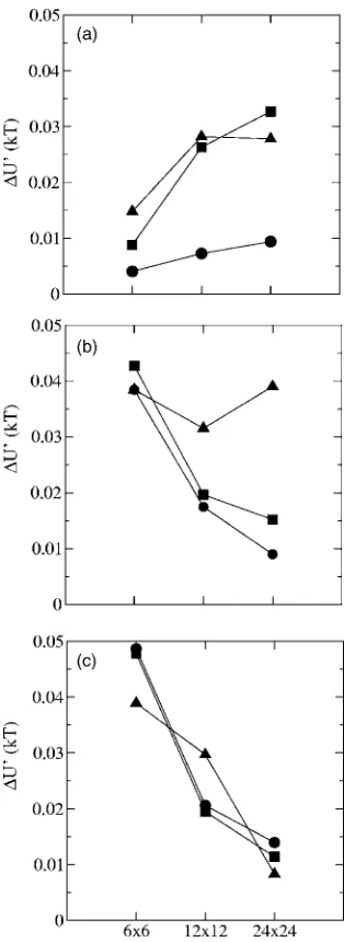
= 1, the reason that all the patterns are transferred equally well to the surface has to do with the energy. Figure 3 shows the average difference⌬U⬘
between the equilibrium energy per segment, when a target pattern is applied and that when no target pattern is applied, keeping all of the parameters the same. The filled black circles in Fig. 3共a兲 show that at z⬘
= 1 the ⌬U⬘
for the 6⫻6 pattern 共0.00396kT兲, the 12 ⫻12 pattern共0.0072kT兲, and the 24⫻24 pattern共0.0094kT兲 are all less than 0.01kT. This means that when the target pattern is applied at z⬘
= 1 regardless of the pattern size, the energy of the system is close to the case when no pattern is applied. In other words, we do not have to force the chains into unfavorable conformations when we apply a target pat-tern atz⬘
= 1 for this chain length. When the pattern is applied atz⬘
= 2 orz⬘
= 3, the 6⫻6 pattern is transferred to the sur-face better than the 12⫻12 and 24⫻24 patterns. This is because the⌬U⬘
for the 6⫻6 pattern is lower than the⌬U⬘
for the 12⫻12 and 24⫻24 patterns关Fig. 3共a兲兴. This means that when the 12⫻12 and 24⫻24 patterns are applied at z⬘
= 2 or z⬘
= 3, the chains are forced to be in unfavorable conformations and the energy is high relative to the case when no target pattern is applied. The chains try to resist these unfavorable conformations and the pattern transfer is reduced.Thus in the case of chain length 12, for allz
⬘
considered, the 6⫻6 pattern helps the chains of length 12 adsorb in favorable conformations and maintain the energy of the sys-tem close to the energy of the syssys-tem when no pattern is applied. When the 12⫻12 and 24⫻24 patterns are applied we force the copolymer chains to adopt conformations that increase the energy; the chains resist those conformations and in turn reduce the pattern transfer.For chain length 18, when the pattern is applied at z
⬘
= 1 or z⬘
= 2, the 12⫻12 and 24⫻24 patterns aretrans-ferred to the surface slightly better than the 6⫻6 pattern
共Table I兲. When the target pattern is applied at z
⬘
= 3, the 6⫻6 and 12⫻12 patterns are transferred to the surface bet-ter than the 24⫻24 pattern共Table I兲. Forz⬘
= 1, the 12⫻12 and 24⫻24 patterns are transferred to the surface better than the 6⫻6 pattern because the ⌬U⬘
for the 12⫻12 pattern共0.018kT兲and the 24⫻24 pattern共0.009kT兲are lower than the⌬U
⬘
for the 6⫻6共0.038kT兲pattern关circles in Fig. 3共b兲兴. This means that the 12⫻12 and 24⫻24 patterns help the chains form conformations that bring the energy of the sys-tem close to the energy when no pattern is applied. Contour plots, such as the ones in Fig. 4, help us to understand the conformations that the adsorbed chains adopt. As mentioned previously in Sec. II B, the conformations of the adsorbed chains are deduced from ␣, the fraction of chain length ad-sorbed, and, the ratio of the number of adsorbed segments on top of type 1 sites to the total number of adsorbedseg-TABLE I. Pattern transfer parameter PTP共z= 0兲for different chain lengths and pattern sizes.
z⬘ Pattern N= 12 N= 18 N= 24
z⬘= 1 6⫻6 0.46 0.47 0.46
12⫻12 0.46 0.49 0.50
24⫻24 0.46 0.49 0.50
z⬘= 2 6⫻6 0.24 0.29 0.32
12⫻12 0.19 0.32 0.37
24⫻24 0.18 0.32 0.39
z⬘= 3 6⫻6 0.10 0.17 0.20
12⫻12 0.04 0.17 0.23
24⫻24 0.03 0.14 0.24
ments. When a large fraction of chains adsorb in loop con-formations, ␣艋0.5 and = 0.5. When a large fraction of chains adsorb in flat conformations, ␣⬎0.5 and = 0.5. When a large fraction of chains adsorb in brush conforma-tions, ␣⬍0.5 and Ⰷ0.5 or Ⰶ0.5. For clarity, data from such contour plots are tabulated in Table II which shows the conformations of the adsorbed chains for all the chain lengths and all pattern sizes applied at z
⬘
= 1, z⬘
= 2, and z⬘
= 3, and when no pattern is applied.For chain length 18 and z
⬘
= 1, the comparison of the adsorbed chains conformations with those when no pattern is applied can tell us why the 12⫻12 and 24⫻24 patterns get transferred to the surface better than the 6⫻6 pattern. When no pattern is applied for chain length 18 the chains adsorb in conformations similar to the case when the 6⫻6 and 12⫻12 patterns are applied atz⬘
= 1共Table II兲. However, for the 6⫻6 pattern andz⬘
= 1,⌬U⬘
is not low even though theconformations are similar to those when no pattern is applied
关Fig. 3共b兲兴. On the other hand for the 24⫻24 pattern and z
⬘
= 1 , ⌬U⬘
is very low, although the conformations are dif-ferent from those when no pattern is applied. Thus it is clear that there can be many conformations of the adsorbed chains leading to a U⬘
close to theU⬘
when no pattern is applied. Forz⬘
= 2, the 12⫻12 and 24⫻24 patterns are transferred to the surface better than the 6⫻6 pattern because the⌬U⬘
for the 12⫻12共0.020kT兲 and 24⫻24共0.015kT兲 patterns are lower than the ⌬U⬘
for the 6⫻6共0.043kT兲 pattern 关squares in Fig. 3共b兲兴. The conformations of the adsorbed chains when no pattern is applied for chain length 18 is similar to the case when the 6⫻6 pattern is applied atz⬘
= 2共Table II兲, but the ⌬U⬘
is not low for the 6⫻6 pattern. As was the case for z⬘
= 1, the conformations of the adsorbed chains for the pat-tern that has the lowest value of ⌬U⬘
are not similar to the conformations of the adsorbed chains when no pattern isTABLE II. Fraction of chains in the system adsorbed in different conformations.
z⬘ Pattern
N= 12 N= 18 N= 24
Flat Loop Brush Flat Loop Brush Flat Loop Brush
z⬘= 1 6⫻6 0.09 0.09 0.04 0.05 0.14 0.20 0.06 0.25 0.19
12⫻12 0.08 0.09 0.09 0.06 0.11 0.23 0.06 0.22 0.19
24⫻24 0.06 0.09 0.13 0.04 0.09 0.36 0.04 0.15 0.38
z⬘= 2 6⫻6 0.10 0.09 0.03 0.07 0.12 0.22 0.07 0.22 0.18
12⫻12 0.10 0.08 0.03 0.06 0.11 0.25 0.07 0.21 0.29
24⫻24 0.09 0.07 0.05 0.05 0.09 0.30 0.05 0.16 0.41
z⬘= 3 6⫻6 0.10 0.08 0.04 0.07 0.12 0.22 0.07 0.22 0.17
12⫻12 0.10 0.08 0.05 0.07 0.11 0.21 0.07 0.21 0.18
24⫻24 0.10 0.09 0.03 0.07 0.11 0.19 0.07 0.19 0.31
No pattern 0.09 0.07 0.04 0.07 0.14 0.23 0.07 0.21 0.19
applied. For z
⬘
= 3 the ⌬U⬘
for the 6⫻6共0.038kT兲 and the 12⫻12共0.032kT兲 patterns are lower than the ⌬U⬘
for the 24⫻24共0.039kT兲pattern关triangles in Fig. 3共b兲兴. The confor-mations of the adsorbed chains of chain length 18 when no pattern is applied共Table II兲are similar to the cases when the 6⫻6 and 12⫻12 patterns are applied atz⬘
= 3共Table II兲, and the ⌬U⬘
for the 6⫻6 and 12⫻12 patterns are the lowest. Thus the conformations of the adsorbed chains for the pat-tern that has the lowest⌬U⬘
are similar to the conformations of the adsorbed chains when no pattern is applied. However, since the same trend was not observed for z⬘
= 1 andz⬘
= 2 cases we cannot conclusively relate the⌬U⬘
and the confor-mations.Thus in the case of chain length 18, the patterns that have low⌬U
⬘
get transferred to the surface better. In order to achieve a low⌬U⬘
the conformations of the adsorbed chains do not necessarily have to match the case when no pattern is applied.For the longest chains共chain length 24兲when the target pattern is applied atz
⬘
= 1, the 12⫻12 and 24⫻24 patterns are transferred to the surface better than the 6⫻6 pattern共Table I兲. Forz
⬘
= 2 orz⬘
= 3, the 24⫻24 pattern is transferred to the surface better than the 6⫻6 and 12⫻12 patterns共Table I兲. Analysis of the data in Tables I and II and Fig. 3共c兲 similar to those described above for the chain lengths 12 and 18 cases reveals the following trends. For chain length 24, when the 12⫻12 pattern is applied at z
⬘
= 2 and z⬘
= 3 and when the 6⫻6 pattern is applied atz⬘
= 1 the chains adsorb in conformations similar to the no-pattern case. However, for all three cases, z⬘
= 1, z⬘
= 2, and z⬘
= 3, the 24⫻24 pattern has the energy closest to the energy when no pattern is ap-plied. Thus we can conclude that even if the conformations are not similar to the no-pattern case, the energy of the sys-tem can be maintained close to the energy when no pattern is imposed.B. Pattern transfer for different pattern sizes
When the 6⫻6 pattern is applied at z
⬘
= 1, the PTPs共z = 0兲are almost equal for all chain lengths共Table I兲, implying that the 6⫻6 pattern is transferred well, regardless of the chain length. When the 6⫻6 pattern is applied atz⬘
= 2 and z⬘
= 3, the pattern transfer to the surface improves as chain length increases. This is because longer chains have a higher fraction of adsorbing chains forming loop and brush confor-mations than the shorter chains共Table II兲. When the adsorb-ing chains form loops, a part of the chain extends to z⬎1 layers and thus bridges the pattern between the different lay-ers. In order to transfer the pattern well between the layers we need to maintain a connectivity between the different layers. Therefore the systems with chains of length 24, which have a higher fraction of chains adsorbing in loop and brush conformations, transfer the patterns to the surface better than the systems with chain lengths 12 and 18.When the 12⫻12 pattern is applied at z
⬘
= 1, z⬘
= 2, or z⬘
= 3, the values of the the PTPs共z= 0兲in Table I reveal that the 12⫻12 pattern gets transferred to the surface best for chain length 24. When the 24⫻24 pattern is applied at z⬘
= 1, the PTP共z= 0兲 is higher for chain lengths 24 and 18than for chain length 12共Table I兲. For z
⬘
= 2 and z⬘
= 3, the PTP共z= 0兲 is again highest for chain length 24 共Table I兲, implying that the pattern transfer to the surface is best for longer chain lengths. The reason why chain length 24 has the best pattern transfer is the same as discussed for the 6⫻6 pattern.C. Copolymer bulk adsorbed on the designed surfaces
So far, we have picked a target pattern, biased the ad-sorbed copolymer film to adopt that target pattern at a de-sired distance from the surface, let the pattern be transferred through the adsorbed layers to the surface, and designed the surface in response to the target pattern. The next question to be asked is the following: If a bulk of copolymers in a ran-dom configuration is placed on the designed surface, can the designed surface induce the target pattern in the adsorbing layers? Answering this question will also reveal if we can determine beforehand what pattern must be present on the surface to induce adsorbing copolymer layers to attain a tar-get pattern at a certain distance from the surface.
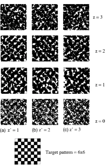
In order to answer the question posed above, we allow the designed surfaces obtained in each of the cases discussed in Sec. III B to adsorbABdiblock copolymer bulk initially in random configurations. We term this “the test stage.” Our purpose here is to test if the designed surfaces can induce the target pattern that was used originally to form the surface pattern. Figure 5 shows how the AB copolymer chains of length 12 respond to the surfaces designed for anAB
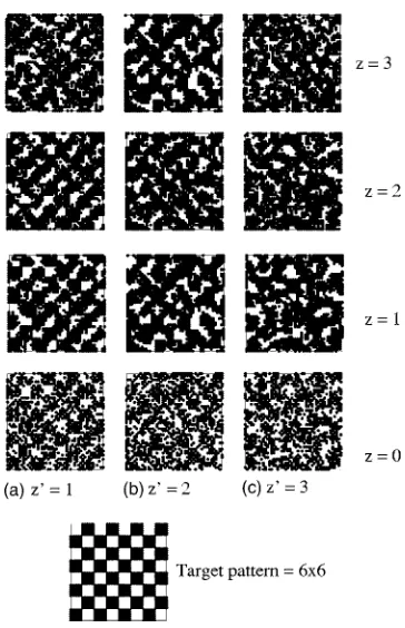
copoly-FIG. 5. The designed surfaces共z= 0兲when the 6⫻6 pattern is applied at共a兲
z⬘= 1,共b兲z⬘= 2, and共c兲z⬘= 3 withT⌫/T= 0.001. The 6⫻6 target pattern is shown for comparison. Also shown are the patterns observed in the bulk at
mer film of chain length 12 when the 6⫻6 target pattern has been applied at 共a兲 z
⬘
= 1, 共b兲 z⬘
= 2, and 共c兲 z⬘
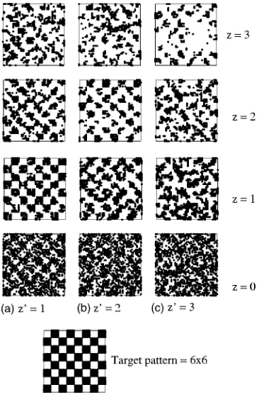
= 3. The de-signed surface patterns at z= 0 are also shown. The data in Fig. 5 indicate that the 6⫻6 target pattern was not induced at any distance from the surface. Similarly, for all chain lengths the designed surfaces for the other patterns, 12⫻12 and 24⫻24, did not induce any of the target patterns in the co-polymer bulk 共not shown here for brevity兲. This is because the patterns applied in the Secs. III A and III B allow the copolymer chains to have conformations that are not neces-sarily similar to the conformations when no pattern is ap-plied. When we bias the copolymer bulk to attain a target pattern at a certain distance from the surface, we force the chains to adopt conformations that will help fit the target pattern, which does not correspond to their natural confor-mation. When there is no bias and the copolymer chains adsorb on the designed surface, they are free to have confor-mations close to their natural conforconfor-mations and therefore do not form the target pattern we wanted them to attain.To ensure that the results above were not an artifact resulting from the low value of weighting factor T⌫/T共=0.001兲used in Eq. 共2兲 to weight the energy minimi-zation term versus the target function fitting term, we run all the above simulations for all chain lengths and all pattern sizes at two other values of the weighting factor: 0.0001 and 0.000 01. When T⌫/T= 0.001, the weighting factor used in the results shown so far, the target function fitting term is weighted 1 / 10 the energy minimization term in the accep-tance criterion. When T⌫/T= 0.0001 and T⌫/T= 0.00001 the target function fitting term is weighted equal to and ten times
the energy minimization term, respectively, in the acceptance criterion. Figures 6 and 7 show how the AB copolymer chains of length 12 respond to the surfaces designed for an ABcopolymer film of chain length 12 when the 6⫻6 target pattern has been applied at 共a兲 z
⬘
= 1, 共b兲 z⬘
= 2, and共c兲z
⬘
= 3 using values of weighting factorsT⌫/T= 0.0001 and T⌫/T= 0.00001. In both cases we see that the target pattern is not induced in the copolymer bulk. This implies that irre-spective of the weighting factor while designing the surface pattern, we do not induce the target pattern in the bulk.In order to compare the system at the test stage to the system during the design, we show the designed surfaces
共z= 0兲and the patterns observed in the bulk atz= 1, 2, and 3 during the design stage when the 6⫻6 pattern is applied in a bulk of diblock copolymers of chain length 12 at 共a兲 z
⬘
= 1,共b兲z
⬘
= 2, and 共c兲 z⬘
= 3 with T⌫/T= 0.000 01 in Fig. 8. The pattern obtained in thez= 1 layer of the bulk during the sur-face design when a pattern is applied atz⬘
= 1共Fig. 8兲is not the same as the pattern obtained in thez= 1 layer of the bulk during the test stage共casez⬘
= 1 in Fig. 7兲.In Table III we tabulate the average equilibrium⌬U
⬘
for the chains in the system:共1兲during surface design, i.e., when the target pattern is applied atz⬘
and the surface reorganizes itself in response to the target pattern, and 共2兲 in the test stage, i.e., after the new copolymer bulk has been adsorbed and equilibrated on the designed surface. The data in part共1兲 of Table III are the same as the data plotted in Fig. 3, i.e., during surface design when the target pattern is applied atz⬘
with T⌫/T= 0.001. In part 共2兲 of Table III, the cases where the⌬U⬘
values are smaller than the corresponding⌬U⬘
val-FIG. 6. The designed surfaces共z= 0兲when the 6⫻6 pattern is applied at共a兲
z⬘= 1,共b兲z⬘= 2, and共c兲z⬘= 3 withT⌫/T= 0.0001. The 6⫻6 target pattern is shown for comparison. Also shown are the patterns observed in the bulk at
z= 1, 2, and 3 during the test stage when diblock copolymers of chain length 12 are adsorbed on the designed surfaces.
FIG. 7. The designed surfaces共z= 0兲when the 6⫻6 pattern is applied at共a兲
ues in part 共1兲 are shown in bold. These cases 共shown in bold兲during the test stage have energy closer to the energy of the natural conformations than the corresponding cases during the suface design. This reveals that for most cases when we do not force a target pattern on the adsorbed layers and adsorb the copolymer chains on the designed surface
共test stage兲, the system prefers to attain an energy that is close to that of their natural conformations and therefore do not induce the target pattern in the adsorbed layers.
IV. SUMMARY
We performed lattice Monte Carlo simulations to study how symmetric diblock copolymers transfer a pattern
through the adsorbed layers to the surface. We applied a target pattern in the copolymer film at a certain height above the surface, performed chain moves to maintain the target pattern, and allowed the surface to rearrange itself in re-sponse to the target pattern. The attractive interactions be-tween the copolymer segments and surface共⑀A1and⑀B2兲and the attractive interactions between the like segments of the copolymer 共⑀AA and ⑀BB兲 enabled the surface to rearrange,
forming a pattern similar to the target pattern. We varied the chain length, pattern size, and the height above the surface
共z
⬘
兲 where the pattern was applied to study their effect on pattern transfer.For constant chain length, the pattern that brings the energy of the system close to the energy when no pattern is applied is transferred to the surface the best. For the pat-tern that is transferred the best, the conformations of the adsorbed chains are not necessarily the same as when no pattern is applied. This shows that there can be many con-formations that can bring the energy of the system close to that when no pattern is applied. For constant pattern size, increasing the chain length results in an increase in the extent of pattern transfer to the surface. This is because longer chains are able to adsorb in the form of brushes and loops that help transfer the pattern between adsorbed layers down to the surface.
After designing the surfaces, we tested if the surfaces could induce the target pattern back into the adsorbed layers of a new copolymer bulk in a random configuration. We found that for all the cases the surface pattern was not in-duced back into the adsorbed layers. This is because the target pattern we applied in the bulk when designing the surfaces did not let the chains attain energy close to that of their natural conformations.
ACKNOWLEDGMENTS
This work was supported by the Office of Energy Re-search, Basic Sciences, Chemical Science Division of the U.S. Department of Energy under Grant No. DE-FG05-91ER14181.
TABLE III. Average equilibrium⌬U⬘for different chain lengths and pattern sizes共1兲during surface design and
共2兲in the test stage.
z⬘ Pattern
共1兲 共2兲
N= 12 N= 18 N= 24 N= 12 N= 18 N= 24
z⬘= 1 6⫻6 0.0041 0.0384 0.0486 0.0061 0.0025 0.0028
12⫻12 0.0073 0.0175 0.0206 0.0013 0.0120 0.0150
24⫻24 0.0094 0.0089 0.0139 0.0044 0.0089 0.0014
z⬘= 2 6⫻6 0.0088 0.0427 0.0478 0.0016 0.0220 0.0190
12⫻12 0.0263 0.0196 0.0195 0.0077 0.0042 0.0190
24⫻24 0.0327 0.0152 0.0114 0.0015 0.0041 0.0150
z⬘= 3 6⫻6 0.0148 0.0384 0.0389 0.0014 0.0053 0.0089
12⫻12 0.0282 0.0315 0.0297 0.0016 0.0087 0.0097
24⫻24 0.0278 0.0390 0.0083 0.0012 0.0096 0.0082
FIG. 8. The designed surfaces共z= 0兲and the patterns observed in the bulk at
z= 1, 2, and 3 during the design stage when the 6⫻6 pattern is applied in a bulk of diblock copolymers of chain length 12 at共a兲z⬘= 1,共b兲z⬘= 2, and共c兲
1S. Walheim, E. Schaffer, J. Mlynek, and U. Steiner, Science 283, 520
共1999兲.
2R. J. Todd, R. D. Johnson, and F. H. Arnold, J. Chromatogr., A 662, 13
共1994兲.
3T. L. Morkved, M. Lu, A. M. Urbas, E. E. Ehrichs, H. M. Jaeger, P.
Mansky, and T. P. Russell, Science 273, 931共1996兲.
4I. Norde, Surface and Interfacial Aspects of Biomedical Applications
共Plenum, New York, 1995兲.
5R. F. Service, Science 270, 230共1995兲.
6J. K. Cox, A. Eisenberg, and R. B. Lennox, Curr. Opin. Colloid Interface
Sci. 4, 52共1999兲.
7M. J. Fasolka and A. M. Mayes, Annu. Rev. Mater. Res.31, 323共2001兲. 8L. Rockford, Y. Liu, P. Mansky, T. P. Russell, M. Yoon, and S. G. J.
Mochrie, Phys. Rev. Lett. 82, 2602共1999兲.
9L. Rockford, S. G. J. Mochrie, and T. P. Russell, Macromolecules 34,
1487共2001兲.
10S. O. Kim, H. H. Solak, M. P. Stoykovich, N. J. Ferrier, J. J. de Pablo,
and P. F. Nealey, Nature共London兲 424, 411共2003兲.
11X. M. Yang, R. D. Peters, P. F. Nealey, H. H. Solak, and F. Cerrina,
Macromolecules 33, 9575共2000兲.
12J. Heier, J. Genzer, E. J. Kramer, F. S. Bates, S. Walheim, and G.
Krausch, J. Chem. Phys. 111, 11101共1999兲.
13D. Petera and M. Muthukumar, J. Chem. Phys. 107, 9640共1997兲. 14D. Petera and M. Muthukumar, J. Chem. Phys. 109, 5101共1998兲. 15J. Genzer, Macromol. Theory Simul. 11, 481共2002兲.
16J. Genzer, J. Chem. Phys. 115, 4873共2001兲. 17J. Genzer, Phys. Rev. E 63, 022601共2001兲.
18J. J. Semler and J. Genzer, J. Chem. Phys. 119, 5275共2003兲. 19J. J. Semler and J. Genzer, Macromol. Theory Simul. 13, 219共2004兲. 20A. Jayaraman, C. K. Hall, and J. Genzer, Phys. Rev. Lett. 94, 078103
共2005兲.
21Y. A. Kriksin, P. G. Khalatur, and A. R. Khokhlov, J. Chem. Phys. 122,
114703共2005兲.