Design of Different types of Aperture Aantennas
using HFSS
M. Puneeth, S. J. S. Rajesh
Department of ECE, KL University, Andhra Pradesh, India
Abstract—
Aperture antennas are used mostly for the microwave frequencies. Aperture antennas can be designed using the different configuration of geometry. These aperture antennas are used for space applications because they are more practical for space applications .There are different types of aperture antennas such as slot antenna, micro -strip slot antenna, Horn antenna, - casse grain. Antenna. In this paper we are going to compare the power radiated by the different types of Aperture antennas.Keywords
—
feed, HFSS , aperture, substrate Coax, Bandwidth.I. INTRODUCTION
1.1ANTENNA:
A radio antenna can be defined as the structure that
which is associated in the transition region where it is in between the free space wave and a guided wave or in between the guided wave and free space wave. Antennas convert the electrons into photons otherwise photons into electrons
Basic equation of radiation TL = Q˙v (A m s−1) ˙I = time changing current, A s−1
L = current element length, m Q = charge, C
˙v=velocity of time change of the charge, m s−2 L = length of current element
So that the current with changing of time radiates, the charge which is accelerated also radiates. Current is mainly focused for steady state harmonic variation. Charge is mainly focused for transients and pulses 1.2 Aperture antennas:
The meaning of aperture is having an opening so that aperture antennas have an opening or hole. These opening of aperture antennas are covered with dielectric material in order to prevent the antenna from environmental effects. Due to the complexity of the mathematics the far field region observations will be restricted. These are essentially set up with metal or dielectric walls. For excitations feed pins or wave guide ports are used.
II. TYPES
OF APERTURE ANTENNAS
2.1. SLOT ANTENNA:
A Slot antenna is commonly used between the frequencies 300MHZ to 24 GHZ. The slot antenna is
admired because the region can be cut out of the surface that is to be mounted and they will have the radiation patterns. The radiation pattern of slot antenna is Omni directional .The slot antenna polarization is linear. The size of slot, shape and design variables is used for tuning the performance.
A slot antenna typically has a flat metal surface which has a slot cut out or a hole. Similar to dipole antenna the electromagnetic waves are radiated by the slot. Instead of line antennas these slot antennas are used at micro wave frequency and UHF. Slot antennas are also used in cell phone base stations and radar systems
Fig.1. Slot Antenna
2.2MICRO-STRIP SLOT ANTENNA
Micro strip antenna has a very simple structure, it is also known as a practical slot antenna. There is a micro strip feed that which is used to couple electromagnetic waves through slot above and the slot radiates. A better isolation is obtained by the micro strip feed antenna between the metal under measurement and the feed. In a design of MMIC and hybrid MIC with passive and active devices these are more ease in integration. When a reflector and thick foam of quarter-wave are inserted micro strip slot antennas produces the radiation patterns of Omni-directional.
dielectrics.
A micro strip slot antenna is a low profile antenna that has a number of advantages over other antennas it is lightweight, inexpensive, and easy to integrate with accompanying electronics [1].The foam’s thickness is chosen such that the slot antenna is placed at quarter-wave length distant from the reflector at the antenna bottom to produce radiation pattern of Omni-directional. The width of the micro strip feed is chosen to be 50-ohm for the ease in the designing the rest of the feed network of the array. Center feeding has to be chosen instead of off-center feeding for efficient use of the array’s limited space. Ansoft HFSS 8.0 has been used for optimizing and designing of antenna dimension
It has a first resonance at about 2.45GHz.At this frequency, the antenna has a wavelength roughly about 0.474,and the bandwidth is about 2.35 to 2.55 GHz.They are most usually used in satellite, spacecraft, aircraft and mobile communication and applications of missile because of many features of attractive such as simple structure, less production cost.
The design of an efficient wide band small size antenna, for recent wireless applications, is a major challenge. Micro strip patch antennas have found extensive application in wireless communication system owing to their advantages such as lowprofile, conformability, low-cost fabrication and ease of integration with feed networks.[3]
Fig. 2 Micro Strip Slot Antenna
Microstrip slot antenna is one of the important elements in modern wireless communication systems and
hence its design optimization is an important aspect for improving the overall performance of the system.[6]
2.3HORN ANTENNA:
Horn antennas have a high gain of directional radiation pattern, these can range to 25dB in some cases, usually it has 10-20dB.There is a wide impedance bandwidth in a horn antennas to make understand that the input impedance is varying slowly over wide frequency range. For practical horn antennas the bandwidth can be an order of 20:1 with a 10:1 bandwidth which is being not uncommon
When frequency increases the gain of horn antenna increases. There is a fixed physical size in horn antenna,
there is also a very little loss in horn antenna.so the gain and directivity are roughly equal in horn antenna Horn antennas have been widely used for space applications from the very beginning due to their capability of being best operation from Megahertz to Gigahertz to Terra hertz range [4]
Advantages of horn antenna over other types of antennas are: (a) High data rate systems needs to be operated at a higher frequency range in order to achieve higher bandwidth. This can be easily achieved using a horn antenna[7].
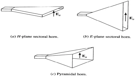
2.3.1. Rectangular Horn Antenna:
Horn antennas are popular in the microwave band (above 1 GHz), high gains are provided by horn. There are three types of horn antennas basically
1. Pyramidal horn 2. E-plane horn 3. H-plane horn
Exponentially horns can be incandesced .A broad frequency is provided for better matching, but it is more expensive and difficult .When feeder is cylindrical wave guide, antenna is a conical horn
High data rate systems needs to be operated at a higher
frequency range in order to achieve higher bandwidth. This can be easily achieved using a horn antenna. [2] 2.3.2. E-PLANE HORN:A sectorial horn that which incandesced in the direction of E-field in the waveguide
2.3.4. H-PLANE HORN:
A sectorial horn that which is incandesced in the direction of H-field in the waveguide
2.3.5 PYRIMADAL HORN:
A Horn antenna with a horn in a four sided pyramid shape which is having a rectangular cross section
In cassegrain antenna primary feed is placed at an aperture which is near the paraboloid vertex .Cassegrain antenna uses a hyperboloid as secondary reflector whose foci coincides paraboloid focus. Hyperboloid secondary reflector is employed by a Cassegrain a feed system focus of secondary reflector coincides with paraboloid focus. Secondary hyperboloid is aimed by feed radiator. The radiations that are emitted by feed radiator are reflected by secondary reflector. The feed elements used may be pure mode circular waveguides and conical horns, rectangular horn antennas, hybrid mode corrugated waveguides and conical corrugated horns depending upon the requirement [5].
Cassegrain antenna is used in telecommunication and radar in which feed radiator is near the concave main Reflector surface and is also used as convex sub reflector .These two reflectors have same focal point. The secondary reflector is illuminated by the energy from feed unit (horn antenna), again it is reflected back to main reflector, and required forward beam is formed.
III. ANTENNA PARAMETERS
3.1. Isotropic antenna:
It radiates in all directions uniformly, it is used as reference antenna
3.2. OMNIDIRECTIONAL ANTENNA:
This antenna covers in azimuth direction equally with an angle in elevated direction, this omnidirectional radiation pattern is most commonly exhibited by wire antennas. 3.3DIRECTIONAL ANTENNA
In these antennas the energy is directed only in one particular direction so that these antennas are called as directional antennas. There is a very high directivity and gain.
3.4HEMISPHERICAL ANTENNAS
In these antennas one half of hemisphere either lower hemisphere or upper hemisphere are covered by radiation pattern.
3.5RADIATION PATTERN
A radiation pattern defines as radiated power variations of an antenna whose direction is away from it. This variation of power is a function of an arrival angle which is observed in the far field of antenna. Standard spherical coordinates are also used. Here Ɵ will be the angle measured along the z-axis and where Ø will be the angle measured along the counter clockwise direction of the x-axis. A pattern is isotropic when the pattern of radiation is equal in all directions. Antennas with isotropic radiation pattern can’t exist practically. But sometimes it can be discussed as a means of comparison of real antennas. Some antennas may also be omnidirectional. Another category of antennas are directional antennas which won’t
have symmetry in the radiation pattern. These type of antennas are typically having the peak direction in radiation pattern..These are some of the examples of antennas with highly directional pattern is slotted waveguide antenna and dish antenna.
3.8Gain:
The antenna’s gain can be describes as that the amount of the transmitted power is in peak radiation direction for an isotropic source. This can be usually stated in a specification sheet of real antennas because that it takes an account of the actual losses that will be occur.
Gain of antenna with 8dB states that receiving power from far antenna will be 8dB higher than that would be received from the same input power of a lossless isotropic antenna.
Gain of Antenna sometimes can be defined as a angle’s function, even though sometimes whenever single number quotes then the gain obtained is the ‘peak gain’ in all directions.
The relation between gain and Directivity of an antenna is given by
G=
ɛᵣ
D
The real antenna gain for a large dish antennas is higher than 40-50 dB. Whereas coming to the Directivity, it is lower than 1.76dB for a real antenna. But it can be never theoretically less than of the 0 dB. Electrically small antennas are incapable for gains of antenna lower than -10dB
The input impedance of an electrical network is states that the equivalent impedance that can be "seen" by a power source connected to that network. If source supplies required current and voltage, such impedance can be calculated by using Ohm’s Law. Input impedance is the electrical network of the Thévenin's equivalent circuit Which is modelled by an RL (resistor-inductor) or an RC (resistor-capacitor) combination, with equivalent values that would have same result response response as same that of that network.
It can also be called as the Z11 in terms of Z-parameters. Whenever we speaking about the exact definition of that depends on the particular field of study.
3.6Power Pattern:
3.7Directivity
Directivity of an antenna is to be defines as that of the ratio of maximum radiation intensity to its average radiation intensity. It can also be denoted by D.
The relation between the Directivity and the Gain can be given by the equation
G=
ɛᵣ
D
here ɛᵣ = efficiency of the antenna 3.9Efficiency:
Efficiency of the antenna is to be defines as the ratio of the total power radiated to that of the total input power supplied to antenna.
Efficiency,
ɛᵣ=Total Power Radiated/Total Input Power
supplied3.10. Beam area
It can be defined as that the integration of normalized power density over a sphere.
IV. DIFFERENT TYPES OF APERTURE ANTENNAS IN HFSS
Fig. 4 slot antenna in HFSS
Fig. 5 Micro-Strip Slot Antenna
Figure
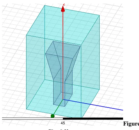
Fig. 6 Horn antenna
Fig. 7 Cassegrain Antenna
V. CONCLUSION
By using different types of aperture antennas we have calculated the power of different types of aperture antennas
VI. RESULTS
Fig. 8 Return Loss of Slot Antenna
The frequency under which slot antenna works between 10.7236 and 9.7236 GHz
Band width= (10.7326-9.7236)=1.0006GHz
Fig. 9 Input Impedance of Slot Antenna
GAIN=4.5472
Fig. 10 2D Gain of Slot Antenna
Fig. 12 Vertical Radiation Pattern for Different Values of ‘phi’
Fig. 13 Vertical Pattern at (phi) =100 5.2. RESULTS FOR SLOT-MICROSTRIP FEED ANTENNA
Return loss of slot-micro strip feed antenna
Fig. 14 Return Loss of Slot Microstrip Feed Antenna
The frequency under which slot microstrip feed antenna works between 11.3819 and 10.3266 GHz
Band width=(11.3819-10.3266)=1.0553GHz Input impedance of a slot microstrip feed antenna
Fig. 15 Input Impedance of Slot Microstrip Feed Antenna
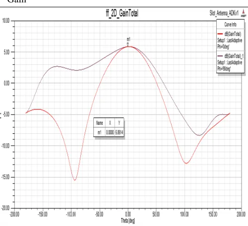
Gain
Fig. 16:2D Gain of Slot Micros Trip Feed Antenna
GAIN=5.8514
Fig. 18 3D Radiation Pattern of Slot Microstrip Feed Antenna
Fig. 19 Vertical Radiation Pattern of Slot Microstrip Feed Antenna
Fig. 20 Vertical Radiation Pattern at ‘phi=100 5.3. RESULTS FOR HORN ANTENNA
Return loss of horn antenna:
Fig. 21 Return Loss of Horn Antenna
The frequency under which horn antenna works between 8 and 12 GHz
Band width= (12-8) =4GHz
Input Impedance
Fig. 22 Input Impedance of Horn Antenna Gain
Fig. 23 Return Loss of Horn Antenna
GAIN=12.9709
Fig. 24 3D Gain of Horn Antenna radiation pattern
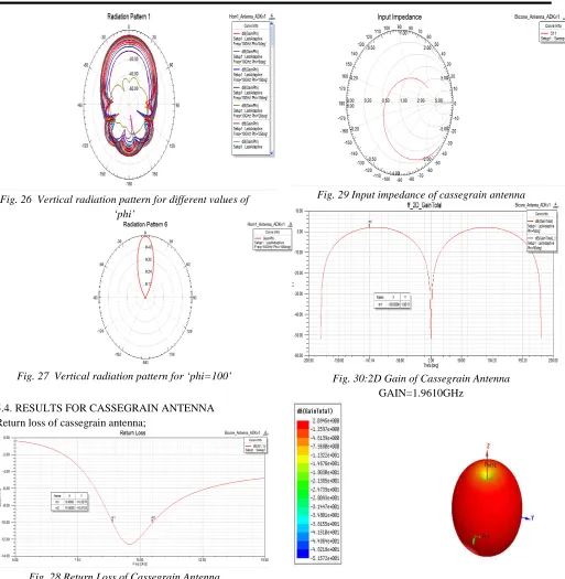
Fig. 26 Vertical radiation pattern for different values of ‘phi’
Fig. 27 Vertical radiation pattern for ‘phi=100’
5.4. RESULTS FOR CASSEGRAIN ANTENNA Return loss of cassegrain antenna;
Fig. 28 Return Loss of Cassegrain Antenna The frequency under which cassegrain antenna works between 10.6000 and 8.9000 GHz
Band width= (10.6000-8.9000) =1.1006GHz
Input impedance of cassegrain antenna:
Fig. 29 Input impedance of cassegrain antenna
Fig. 30:2D Gain of Cassegrain Antenna GAIN=1.9610GHz
Fig. 31 3D Gain of Cassegrain Antenna Radiation pattern
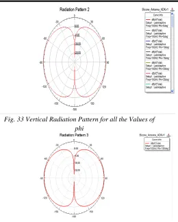
Fig. 33 Vertical Radiation Pattern for all the Values of phi
Fig. 34 Vertical Radiation Pattern for phi=100
REFERENCES
[1] K. Phaninder Vinay, Basheer Ali Sheik, A. Trinadha Rao, “Design and Analysis of Slot Antenna Parameters Using HFSS,” International Journal of Innovative Technology and Exploring Engineering, Volume3, Issue-12, April 1955. May 2014
[2] Shubhendu Sharma “Design and Analysis of Pyramidal Horn Antenna at 8 GHz Frequency,” International Journal of Advanced Research in Electronics and Communication Engineering (IJARECE) Volume 3, Issue 2, February 2014 [3] Pradeep Kumar, Neha Thakur, Aman Sanghi,
“Micro strip Patch Antenna for 2.4 GHZ Wireless Applications,” International Journal of Engineering Trends and Technology (IJETT) – Volume 4 Issue 8- August 2013
[4] M. Ameena banu, N.R.Indira, M.Pandimadevi, “Design of Pyramidal Horn Antenna for UWB Applications,” International Journal of Advanced Research in Computer and Communication Engineering”, Vol. 2, Issue 7, July 2013
[5] Krunal Patel, “Designing Optimized Cassegrain with Balanced Feed,” 2nd International Conference and workshop on Emerging Trends in Technology (ICWET) 2011 Proceedings published by
International Journal of Computer Applications® (IJCA)
[6] Hayat Errifi , Abdenacceur Baghdad , Abdelmajid Badri “Design and Optimization of Aperture Couple Microstrip Patch Antenna Using Genetic Algorithm” International Journal of Innovative Research in Science Engineering and Technology.